Building a 35 mm-scanner

Reverse-mounting is useful for standard camera lenses, as they are optimized for imaging objects in front of the lens from a few meters to infinity to the sensor. The sensor is placed around one focal length away from the back of the camera. In macrowork, the situation is reversed: the lens sits nearer to object of desire than the sensor, so it makes kind of sense to swap input and output planes of the lens. This is what reverse-mounting is all about. Of course, using a macrolens calculated for this situation would even make more sense.

The Schneider Componon-S 50 mm is an enlarger lens, calculated for a very different optical situation than a standard camera lens. In an enlarger, the distance is between lens and negative is larger than the focal length, and the to be exposed photographic paper is also only a few focal lengths away from the lens at most.

The Schneider Componon-S 50 mm was designed for 35 mm work - if you are using it with small formats like Normal or Super-8, your camera sensor will cover only the sharpest central section of the design - which is good. Also, the lens will operate close to a 1:1 magnification, because sensor size and film size are about the same. I do not think that you will see an improvement by reverse-mounting that lens.

For 35mm format film, the lens is actually operating in a configuration vers similar to what it was designed for.

Just a side-note: there used to be Schneider Componon-S 80mm available. I used them in the 80s in my colorlab for enlargements of 6x6 negatives with quite some good results. Using this lens with the smaller 35mm film format would also only utilize the most sharp central region of the lens - but I do not have enough technical data available to really be sure about the feasibility of that 80 mm lens for a film scanner application.

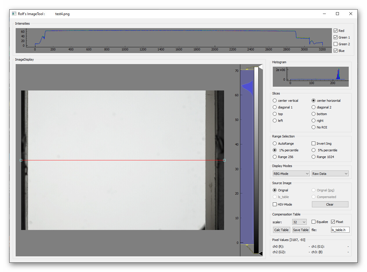
Next: there are two very good reasons for not using any lens at the largest (in terms of light throughput) f-stop. First, you will get a very narrow depth-of-view with such a setting. So any misalignment of the optical setup will lead to one portion of the image being sharp while other regions of the image get least a soft tone because they are slightly out of focus.

Furthermore, lenses used to be designed and manufactured with spherical surfaces. Nowadays, aspherical and freeform manufacturing techniques are available, but the Schneider Componon-S is certainly an old design. Now, spherical lenses perform optimal only near the center of the optical axis. Optical performance gets worse the farther away from the optical axis light passes through the lens. That’s why you explicitly do not want to work with f-stops like 2.8 or so.

Going to very high f-stops is is also not really an option, because in this case, optical diffraction ruins your result (check the Wikipedia article for Airy disk for details).

In summary, there is going to be a sweet spot where you will get optimal results from your lens. For the Schneider Componon-S, this is located around a f-stop of 5.6, with 4.7 and 8 resulting in very similar images. Anything above a f-stop of 8 shows some softing due to diffraction kicking in.

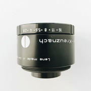
Finally - there are very different versions of this lens available - with metal and plastic, with and without lightpipe. I bougth mine in the 80s of the last century, a Schneider Componon-S 50 mm and a Schneider Componon-S 80 mm, and they are both performing well until today.

4 Likes

Thanks for your explainations about the Componon-S!
So you’d recommend to mount it “the correct way” for 35 mm film and not reverse it. I thought flipping the lens may also give it less space where any scattering light etc. may fall in, but I really don’t know much about photography, so I don’t know if this would help anything at all.

BTW: Assuming I want to photograph the exact same size of the film with the lens in reverse it means it has to get closer to the film. But is the distance between the lens and the sensor increasing or decreasing at the same time?

But I’ll definitely change the aperture to around f/4.7. I assume it’s exactly the dot between the 4 and the 5.6 or is it slightly next to that dot?

The version of the lens I have is the one with the metal barrel (Code 14849 according to the box it came in), so according to this it’s the 5 element / 4 group-version.

What about that issue with the uneven lighting? It can’t be seen that much in the screenshots above, but if you crank up the exposure in those pics you’ll see what I mean:

Would you rather decrease the actual light and increase the exposure time (currently stands at 2998) or vice versa? Or is there anything else I could do to get an even lighting for the entire picture?

A very good explanation from Rolf. you will not need any more about the lens.
All the distances are measured from the optical center of the lens. Since this is a very small lens, and the optical center is inside the lens, there can not be much of a difference if you reverse the lens.
Increasing the light or exposure will not solve the uneven lighting problem. It is not clear what method you employed for diffusion. The problem lies there.
What method did you use for focusing, which is vital since the Depth of Field is very shallow. When focused right, you will be able to see the film grain or dirt on the film. Your captures seems slightly out of focus to me. Look in to this also.
When you stop down the aperture to f5.6 you have to increase the light accordingly with shutter duration (2998 x 4) to get the same exposure (for f4.7 it is a little less). Are you using a 1000W LED? From my experience with real time capturing, I do not think that such a powerful light is required.
My 2 cents.

1 Like

Well, yes. Don’t reverse-mount the lens.

In my opinion, the reverse-mounting technique should be avoided. It’s just a cheap way to use a lens not designed for macro-work as macro-lens. I tried to explain it above, but a picture is probably more helpfull here. Have a look at the diagram on this page, the second picture from the top of the page.

The thing is: any optics is designed and optimized for a specific use case. And you will get the best performance if you are using it as it was designed. Also, the whole mechanical part of the lens is designed accordingly. Typically, the front of a lens is fortified against moisture and dust, the lens often hardened with a special coating. This is not true for the back lens which “lives” just in the cozy darkness of your camera body. If you turn your lens around, you loose all these design features. Also, within the lens, there are shades and other structures minimizing stray light, increasing thus the contrast of the final image. If you you reverse-mount a lens, these design features might still work, but chances are they are less effective.

So, if you can not afford to purchase a lens for macro or close up work, you can mis-use a standard lens by reverse-mounting it. It’s a cheap solution, but not the recommended way. Just purchase a lens which was designed for macro work - that’s the better approach.

Difficult to say in general. Optical wise, in the “thin-lens” approximation, actually nothing would change. But real lenses have separate front- and back-focus planes, designed for the purpose at hand. An example: a modest 35 mm wide angle lens of f=28 mm focused at infinity should be sitting (if it were just a single lens) right at the distance of 28 mm. Clearly, there is no place in a standard 35 mm camera to achieve that. So in practice, the lens is designed to sit farther away from the imaging plane than the stated focal length would suggest. In this case, the back-focus plane is shifted behind the real lens, closer to the camera sensor. Well, real lens systems are practically never “thin” lenses (which would have the focal planes right in the middle of the lens) but have different focal planes, depending in which way you look through the lens. But @Udayarangi is right - it should not make any noticable difference with this lens, as it is mostly a symmetric design.

That is so. However, if your light source can handle it, I would suggest using directly a 5.6 setting. The sharpness in the corners will increase a little bit.

Interesting. I was not aware that two different lens designs existed. That is most probable due to the fact that the old lead-based glasses were phased out due to environmental concerns. The new glass types typically have a lower index of refraction, so you need to redesign the lenses. I am quite sure that both types of lenses do their job.

Well, I do not know what “2998” exposure time stands for. Is this 0.2998 sec? In any case, if your frame is stable during exposure, there’s no loss in extending the exposure time (other than a slightly longer scan time).

Now to the even illumination. First of all - you should never judge illumination with a film in your imaging path (like you did above). Get the film out of your setup, adjust exposure of your camera in such a way that your gate is imaged at a medium intensity level (appearing grey in the image, with intensity values around 128) and take a picture. Examine this picture closely - ideally, it should be just a constant grey value over the whole picture. Well, it won’t. Normally, you will see a drop off towards the edges of your image. That can be caused by a lot of factors. Even if your light source is perfect, your lens will have a limited circle of even light transmission. Intensity will fall off farther away from this central part. Actually, I think Schneider is even giving you this information in their data sheets.

Most probably, judging from the image above, your light source is not centered on the optical axis and also there are indications that you are not using a sufficiently strong diffusor. However, the quality of the diffusor can only be judged once the light source is centered correctly. That should be the first step.

3 Likes

This thread is spectacular. Thanks to all who have contributed their wisdom. And thank you @Doc for sharing your process and results! I agree you issue with the bright spots in lighting are related to diffusion. Have you tried using the diffusion material found inside computer monitors or flat screen TVs? If you cut it up and layer a few pieces together it works pretty well.

1 Like

Thanks again for your posts!

The COB-LED I’m using is this one: YUJILEDS® CRI 95+ 100W COB LED 3200K 5600K - 400H - 2pcs — YUJILEDS High CRI Webstore
And the design for the build is like in the video I posted before (can also be found on the product-page). It’s currently sitting inside the area behind the gate and is diffused by a 50x50x3 mm flashed opal diffusor-glass by KnightOptical: Ground Glass Diffusers | UV silica ground glass | Borosilicate

This glass is sitting right behind the gate, so the glow you can see in the samples is coming through that glass. I have to check again whether the light is pointing at the center of the glass, but I remember there wasn’t much room to change its position.

As for the exposure-time: Unfortunately SpinView doesn’t show any units, but I assume it’s microseconds.

The only thing I can think of is to try taking the light apart and painting the inside of the enclosure black to prevent light bouncing off an edge?

It seems the speed is in microseconds. You can extend the time to 25000 (1/40 th of a second) if you need. You could go further than this, but there will be no need. (I ran my scan at 1/40 when recording at 24 fps with 100 watt tungsten and got pretty good results).
As mentioned by Matthew, I also got very good results using a diffuser from a television backlight panel. I used only a single layer in front of a clear tungsten filament bulb and got this result.

As I have mentioned previously the focusing is a very important aspect. I was struggling to get the focus right and using a 32 inch monitor for focusing solved the problem. Focus at full aperture and stop down to the required 5.6 or 4.7. This is normal procedure who is used to enlarging negatives or old manual aperture lenses. I found out that some times the source frames were out of focus. Do not try to focus on the content especially on a wide shot. Focusing on the film grain is the best method.

Hope this would help.

2 Likes

OK, so probably reducing the actual light and increasing the exposure-time may also help to get rid of the light cones. Maybe it’s just too much light that ends up with creating these circles and it will get better when less light is thrown onto the glass. Or will increasing the exposure-time bring up other problems as more noise etc.?

I’ll try what can be achieved with this. Otherwise I’ll have to check other diffusion methods like the material from a LED-TV you mentioned. @Udayarangi The screenshot from your scanner looks very nice! Very great and even light.

I also read about integrating spheres which are supposed to work extremely well - unfortunately I don’t understand much of how they’d have to be built.

As for the focusing-issue: The preview in SpinView is unfortunately rather bad. I tried to use numbers from a leader to focus, but even at 100% it was hard to recognize whether it’s focussed or slightly out of focus again. But maybe checking the film-grain works better.
Would you suggest trying to focus with a film running or would you rather do it with a single frame standing in the gate?

Thanks for your kind comment. I found that this diffuser is as good ad any complicated systems. As I mentioned in my post this particular capture was using a tungsten filament bulb sitting about 4 inches away from the diffuser. This is a worst case scenario. This simple set up worked for me. Why spend time/money on a more complicated system?

Also this frame was captured at 24 fps using a Rolling Shutter camera. But at the time of the exposure the frame is static since the film transport was intermittent. (I was capturing from a projector).

Focus when the frame is standing at the gate. Before running the system I think it is a good idea to test other functions such as Diffusion, focus etc while the frame is static. Also as Rolf suggested check the diffusion without a film. When you focus at the open aperture and stop down the focus will improve because of the increased depth of field.

1 Like

Didn’t get the chance yet to do further tests, but I hope I can work again on this soon. I’m also currently waiting for different samples from those TV-diffusor-foils you mentioned. Hopefully that’ll solve the problem with the uneven light.
@Udayarangi May I ask if you’re using just a single foil or a combination? I was told that there are between 4-10 of those foils inside a TV, sometimes all the same thickness, sometimes a combination of different versions.

Another thing that came to my mind re: light-adjustments: Rolf suggested to adjust the exposure etc. without a film in the gate and in a way that the intensity-values are around 128 (I assume out of 256). Of course that makes sense, because that’ll be as bright as it gets during a scan.
But is there also a way to make sure that dark detail won’t be crushed then? Will it be captured eitherway if the brightest spot is at a medium level and will come out again during the digital postproduction (e.g. by increasing the exposure-value in DaVinci Resolve etc)?

I hope you know what I mean, it’s not that easy for me to explain. :slight_smile:

Well, that is only for checking the eveness of your illumination. Ideally, the intensity of each pixel (when checked with a color-picker) should be the same across the whole image. Most probably it will not. This exposure setting (128) is only good for checking the illumination, not for scanning any material.

Of course, when actually scanning film, you would adjust exposure in such a way that the brightest points of your frame end up in the 240 to 250 range, if you are using a 8 bit/channel camera. That will give you more shadow-detail. If you care less about blown highlights but more about shadow-detail, you might opt to ramp up exposure even more.

2 Likes

Thanks for the quick reply!
Of course it’d be nice to achieve both: Good shadow-detail and also no clipping highlights. So I’ll try to get the brightest point somewhere around 250 and hopefully it’ll be enough to capture most of the shadow-detail as well.
Looking forward to those next tests and of course I’ll let you know how it turns out.

It is not a foil. A sheet of diffusion. The photo shows only a part of the sheet. Generally it is same size as the LED screen. I used only one layer.

2 Likes

Got the samples today and they’re quite interesting: Some have some kind of mirror-effect, others look more matted. I just tried what happens using a simple flashlight from my iPhone and the results are depending on which sheets are combined in which order. You definitely have to put one of those matted sheets on top to get more even results. If you use another one it just reflects the light to different areas, but it’s not even. Very interesting stuff!

The one you have on that photo looks like the matted ones. I’ll try and see if I can get the light even with just one or a certain combination of these sheets. Might take a while before I can test it, but I’ll sure let you know what happens. Fingers crossed! :slight_smile:

1 Like

If you need I could send a piece of that material. Let me know.

Taking another look at the lamphouse probably also solved the problem: We found a tiny screw that seems to be the reason for the reflection. After putting a piece of tape over that screw the reflection seems to be gone and the light appears to be much more even.

We also tried to adjust the light-exposure, this was the last setting which should be ok. Here’s a RAW- and the corresponding DNG-file with R and B balanced (will be online for 7 days): WeTransfer - Send Large Files & Share Photos Online - Up to 2GB Free
It’s not perfectly even as Rolf already expected it won’t be, but I’d say it looks ok. What do you think?

1 Like

@Doc: I downloaded the raw and converted it with Gimp to a png, without adjusting anything during conversion. First: as this is not a 8bit/channel image, the exposure is kind of lower. The average pixel value in the png ends up at 64, as the dynamical range of the raw material is scaled down to the 8bit-range. Anyway.

If you look at the following image,

you can see that the illumination of your gate is close to perfect. The intensity profile (top diagram) along the red horizontal centerline is as actually quite flat.

There is a tiny speckle visible on the right edge of the film gate. If I stretch the contrast a lot,
you can see this much better:

These speckles might be just dust in the optical pathway. Practially all of them won’t be noticable during a real scan and will be less noticable with a wider f-stop. Some careful cleaning would probably get rid of them, otherwise, one should be able to correct that in the post with an inverse mask.

1 Like

Yes, those speckles is just a little dust in the gate.

Unfortunately it turned out that the cone of light is still there when you’re scanning dark pictures. Since the exposure has been adjusted it now seems even more noticable than before:

Here’s the same frame with the exposure cranked up again:

It is better than before since the right side looks much more even, but that glow is still distracting. Guess we have to try again using the diffusion-material from the TV.

EDIT: Something else just came to my mind: What if this reflection is not from behind, but from somewhere in front of the gate? I just looked at the photos I took last time and I already have something in mind…:

Highly possible that your camera is seeing stray light. Best approach is to cover everything in your optical path with black matte paint. In addition, one can use diaphragms to ensure that no light comes out of the lightbox, except where the film gate is.