I’m thinking it’s stray light as well. Practically all the commercial scanners have the camera in a blackened column, you can try some black tape over that to begin with, but then you ideally want to get a piece of PVC pipe or something (probably similar to what @cpixip has in mind “diaphragm”) cut it so it fits as tight as possible between the camera and the gate paint the inside matte-black and then tape it on. You’ll need to be able to easily remove it for cleaning of course.
1 Like
Got it!
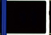
It was indeed stray light reflecting from some other projector-parts. After taping them and then trying again the scans now look nice and even - without a strange glow somewhere. ![]()
Here are some new DNGs (will be gone in 7 days): Unique Download Link | WeTransfer
And another JPG from one of those DNGs with high exposure:
We’ll have to see which options we have to build some sort of “tunnel” from the optics to the gate to make sure nothing else may come into the path again, but we have to think and check first how this can be done. If someone has suggestions, I’m happy to hear them! @filmkeeper already mentioned a PVC-pipe or similar. Maybe some of you guys already have made your own experiences and can share them.
But I think the results are quite nice now. What do you say?
3 Likes
The scan looks nice except the picture is missing! ![]()
If you download the DNGs from the WeTransfer-link you’ll also be able to see some more pics from a Trailer and not just the black frame. 
1 Like
Oh you’ve redeemed yourself! That’s one of my favourite movies, email it to me right away I want to see the whole trailer! 
It looks fantastic.
1 Like
Have to dig this thread up again.
While the machine is delivering great results (thanks again to everyone here who helped getting it going!) there is one particular issue which is still giving us headaches. @cpixp already mentioned it in his post on April 1: Dust.
Right behind the gate there is this opal glass for diffusion, so there’s not much space between the film and the glass (just a few mm). Of course this glass is cleaned before every scan, but sometimes (especially with dirtier films) it happens that dust flies onto the glass during scanning, leading to dark, soft spots in the image. Here’s an example:

A dry cleaner is already attached to the machine which helped to make it happen less often, but as mentioned it still keeps happening. Is there anything else we could do to prevent this or is it just trial and error and rescanning all the time in case it happens again? Maybe someone here has some more ideas that might help.
Of course cleaning the film manually is an option, but depending on how dirty the films are this would become a hell of work - and sometimes it even happens with actually pretty clean film.
Just an idea that came to my mind: Do you think it might help to increase the distance between that diffusion-glass and the film? Right now it’s really just a few mm, maybe a bigger distance (e.g. 1-2 cm) would help to make the dust on the glass invisible? Or would this also have a negative impact on the quality of the scans when it comes to diffuse and even illumination?
Maybe some of you here also have something for diffusion in your setups and can give me an idea about how big the distance between film and diffusor is there?
Distance will help a bit. There’s about 4-5" of space between the film and the top of the lamp house on the ScanStation (less on the Lasergraphics Archivist, from what I can tell from pictures), and that does help to mask dusk quite well.
Another option (though a bit more complicated), would be to add an air blast that periodically blows air onto the area between the film and the diffusion. I think the Rank Cintel machines had something along these lines, and there’s a similar mechanism on the tool height gauge for our CNC Router, to clear it of debris that might collect on it while cutting. Mechanically/electrically it’s pretty easy to do, you can use a simple solenoid based valve that’s triggered with a relay. It would mean connecting some kind of small compressed air tank to the system as well.
1 Like
Thanks for your suggestion!
Right now there’s just a few mm of space between the film and the diffusor - so compared to 4-5" (which is 10,1 - 12,7 cm) in the ScanStation it’s quite a difference. ![]()
I guess there’s not enough space for a constant airflow though. I posted this picture before:
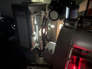
The setup is based on a projector and the light is completely mounted into the lamp-house and there wasn’t much space left, so even the diffusor probably can’t be put 10 cm backwards, but hopfeully less, e.g. 2-3 cm, would also help to get rid of that dust-issue, which is really frustrating.
1 Like
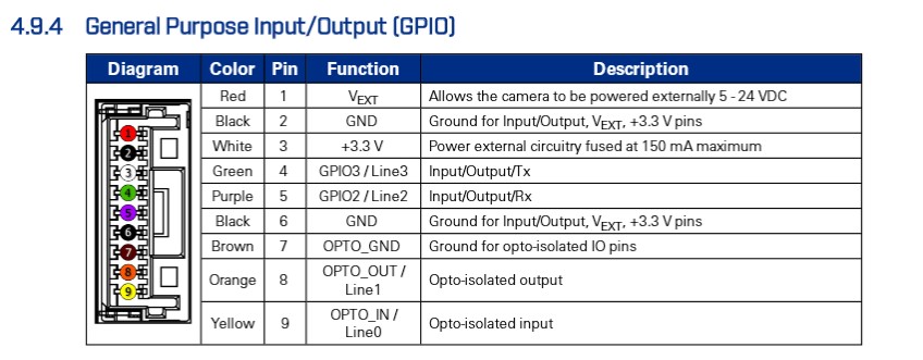
@Doc @The_Projectionist for the life of me I can’t figure out how to get GPIO triggers working. My GPIO cable came with blue and brown twisted together, and black exposed via connector (black = Line 0).
Am I missing something in these settings? Or in another tab of the interface?
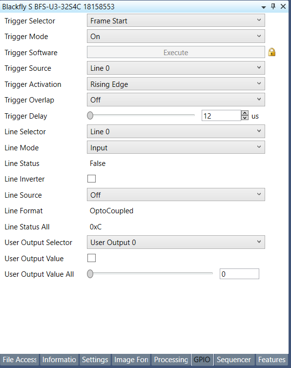
For me it was the red wire (Line 2) which had to be selected for GPIO. The rest is just set exactly as in your screenshot.
2 Likes
For the acquisition mode I’m doing continuous, otherwise the settings seem good.
I had some issues with the length of the trigger pulse not being long enough for the camera to recognize it. I think the minimum is 12us.
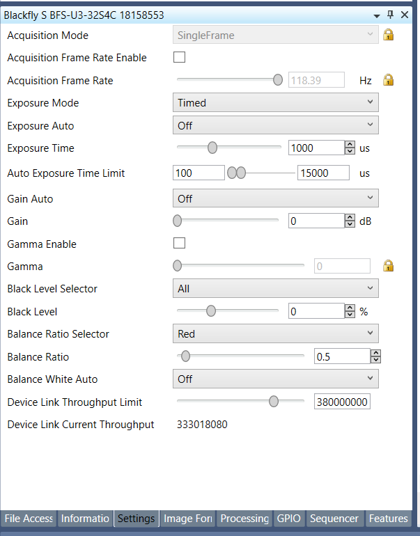
Oh, sorry - I was just referring to the GPIO-settings. As for the other settings I’m also using “Continuous” for the acquisation mode and the Balance Ratio is set to 1 for all colors. That makes the preview look rather green and dark, but that’s just the preview in SpinView. The exposure-time is also set to the minimum (IIRC 3000us in my setup), the exposure is managed with the actual light-source.
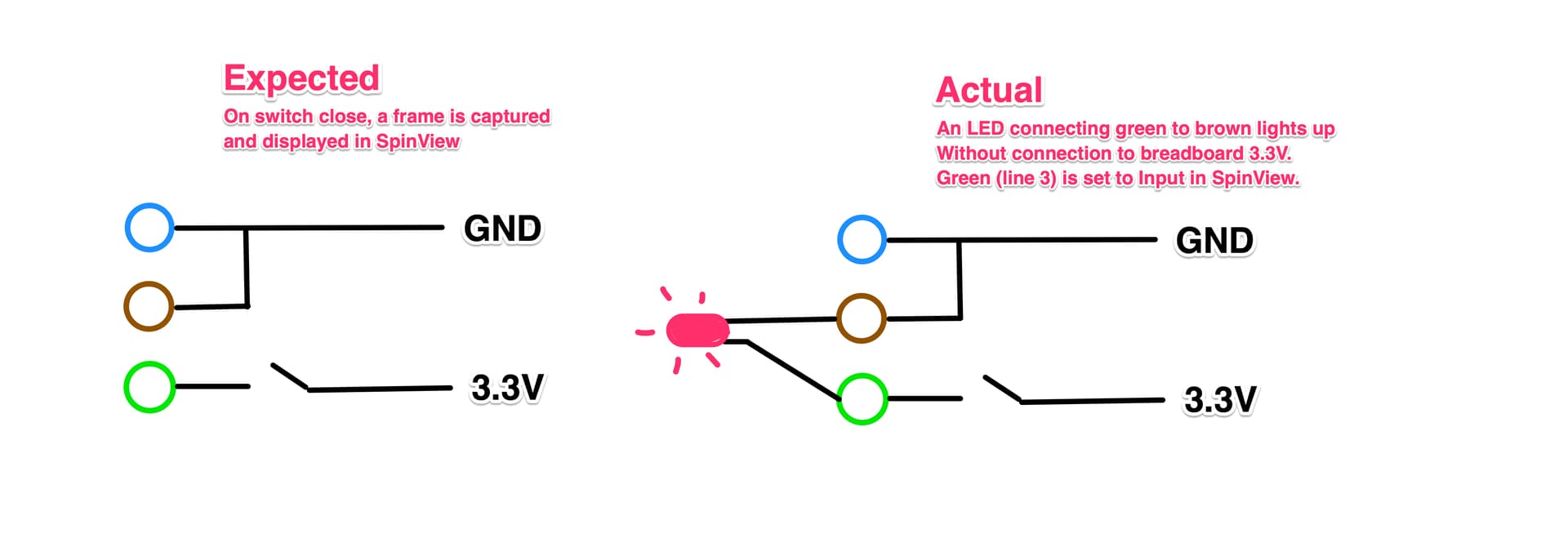
Oh, I should try the continuous mode thank you. I’m losing my mind over here and questioning my sanity. This should be very very simple! I contacted Flir support and they suggested using the green and brown wires, which also did not work. Interestingly, even when I set the LineMode to “Input” for either green or red lines, I still get voltage out of them. Enough to light up an LED (about 2.9V). Strange, no?
I’ll give the continuous thing a try.
I’m powering the camera through the GPIO connector so Green is +12 and Brown is GND. For the trigger I’m using the opto-isolated input. Blue to GND and Black directly to a pin on my teensy. Then your trigger from Line 0 on the rising edge should work.
With the continuous mode I can turn Trigger Mode off to view the real time image from the camera and set up exposure and focus. Then I turn it on to do the capture.
Finally got it to work. It was unclear to me that I needed to click the green “Play” button in order to use the trigger feature. I assumed it was specific to video capture. ya know, because it’s a PLAY BUTTON FOR CRYING OUT LOUD.
The folks at Flir gave me this GIF which was helpful. I’m leaving it here for anyone who comes after me. At the end, you’ll see they test the trigger mode with a software signal (a click on the Execute button). That ensures that the camera can receive a trigger and that it produces a still. From there, you would switch that input to a Line and proceed with hardware trigger.
Another note, the GPIO wires differ within the Blackfly family of cameras. You will want to make sure you are looking at the correct datasheet for your exact model.
I realize that other people successfully set this up without these troubles and obvious mistakes, but I am reminded in this ordeal just how important good, intuitive user interface design and documentation are. We can do better ![]()
This relates to building a 16mm scanner. How would I modify the gate/aperture to view the entire frame and optical track? Currently, as is with other projectors, there is only a cutout for one frame of film.
I’m a little late…just read this thread.
Regarding the hall effect trigger, I think a more elegant solution might be the optical trigger.
I used it for a very long time with a Flir Chameleon camera.
Here is the description (in French, sorry, but that shouldn’t be a problem):
Schéma trigger V2.pdf (25.9 KB)