The same results. I sent to you the file crash,log
crash.zip (1.3 KB)
The same results. I sent to you the file crash,log
crash.zip (1.3 KB)
I didn’t expect anything else; that was actually the point.
Except that with the crash file, we know why.
Except that now I know it’s a Basler DLL version issue:
I still need to adapt the application, and it’s not just a matter of changing the DLL.
After that, there will be the issue of which version to use when new updates of this DLL are provided.
@eldi : The last version available here:
https://kdrive.infomaniak.com/app/share/2305306/b538145a-8bfe-4fb4-bfeb-d3556be61541
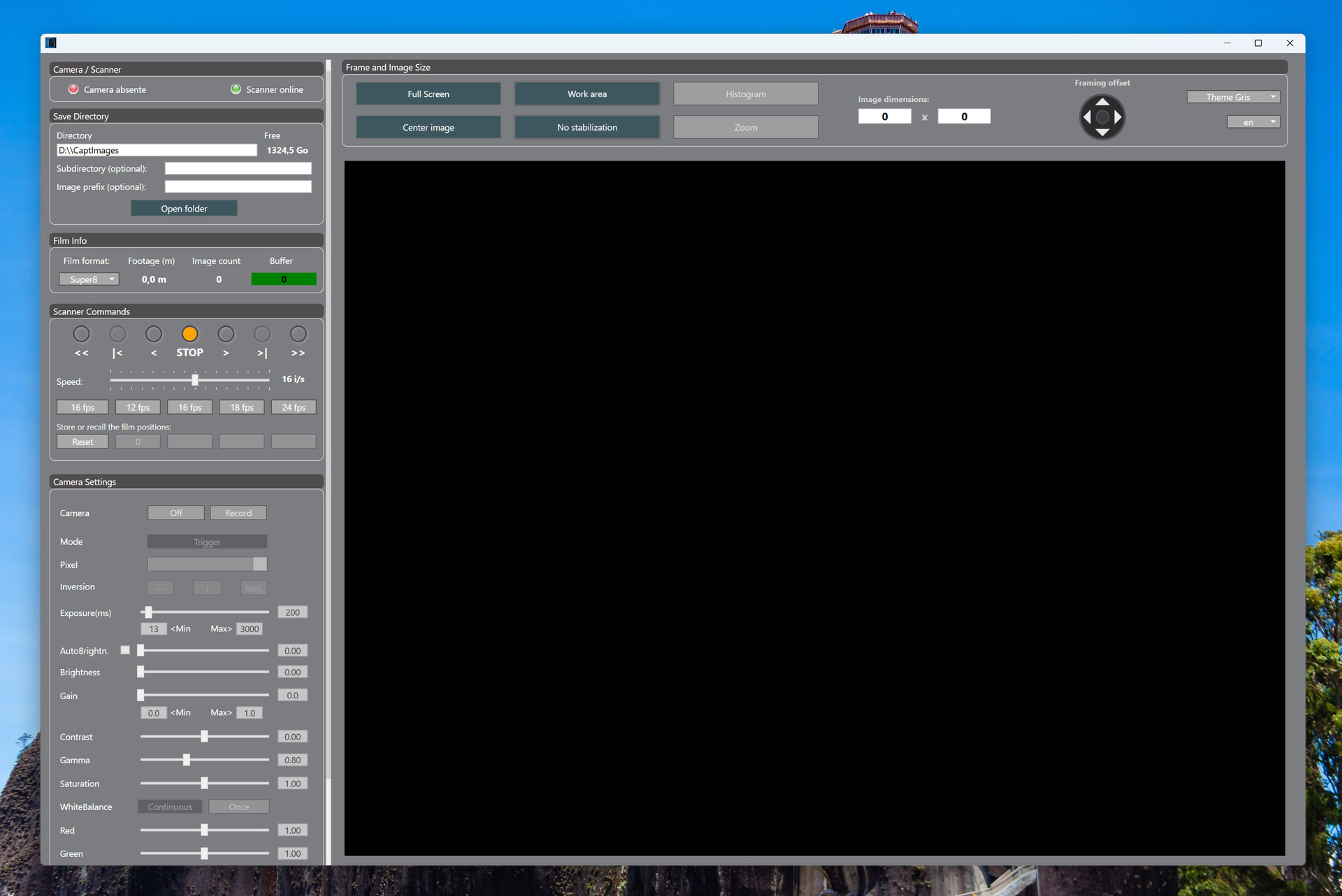
This version fixes an issue caused by a Basler DLL version mismatch that prevented the application from launching.
The application now works with Basler pylon 26.04.1 Software Suite, which is the latest current version and the one you have.
Any other versions present on your computer will trigger a warning message and cancel the installation.
After the clarifications and wanting to see if it works, I installed Pylon 8 and it is fine, it works and communicates with the Teensy. The control buttons work. So I believe that when the final assembly is done, if no mistake occurs, it will work perfectly. Of course, the problem with the DLL version needs to be fixed so that it will work with future upgrades of Pylon. Before you made the changes, I tried with Pylon 8; now it also works with the latest Pylon 24. Thank you.
I’m not really sure how to proceed. At least the user is now informed that the Basler Pylon version is no longer compatible with the application, which is already a good start.
The issue is that the installed Basler DLL is a wrapper that itself calls other DLLs included in the Basler Pylon software. However, I’m not sure whether I’m allowed to use those DLLs for a non-Basler distribution.
Another obstacle is that bundling all these DLLs into ScanFilm would lock the application to a specific version. So, in any case, an update would still be required in order to benefit from the latest DLL versions.
GenICam might make things easier, but that remains to be seen; I’m not a specialist.
For your information, this application is open to other scanners controlled by Arduino or similar systems. The scanner/application communication protocol is available in the documentation. A maker could start, move forward, move backward, or regulate the speed of their scanner without too much trouble.
I agree with the idea. This way, it will also be possible to use any camera that is compatible with this standard, making the choice of camera easier.
Hi everyone,
This thread is seriously impressive, the builds here are incredible. I’ve been obsessed with film scanning and film emulation for the last couple of years, and Roland’s design is what finally convinced me to start building my own scanner.
I’m coming at this mainly from a color science perspective. I work as a colorist, so my goal is not only to scan film mechanically, but to get the most accurate and useful color pipeline possible from the scanner.
My main question is about the Basler camera data and color management:
Once you capture the Basler raw/Bayer data and debayer it, how are you treating that RGB data? Are you converting it into a known working color space such as XYZ, ACES, Cineon/log, or another calibrated scanner space? Or are you mostly using the camera’s default color processing / white balance and then correcting visually afterward?
In other words, I’m trying to understand the best workflow for going from:
Basler raw sensor data → debayered RGB → calibrated working color space
especially when scanning color negative film.
Any insight into how you handle color calibration, scanner profiling, or transforms from the Basler data would be extremely helpful.
@Immortal_Robot :Thank you for your interest in this project.
Unfortunately, I am not a color specialist like you. Others on this forum excel in this field, and I am often far outmatched by their expertise.
I can only speak from my own experience. Here is how I proceed:
I set the white balance only once, using a clean white leader from a film — one that looks very white to my eyes, not yellowish.
During capture, the only automation I use on the camera is the exposure time setting.
I limit the maximum exposure time so as not to brighten dark shots too much and to avoid an excessive increase in noise — both film grain and video noise.
The capture format is raw .tiff, in RGB, 8 bits per channel. For capture, I work only with .tiff files, so I can be sure my capture is never corrupted along the way.
The images are then processed with software I am currently improving, which uses Avisynth for dust removal, sharpening, and sometimes Gammac for color.
I admit that, from time to time, I give in to a light treatment in Topaz, which can work miracles — though not always.
The final edit is done in DaVinci Resolve.
On a film, colors vary constantly. The lighting during shooting, the way the film has been stored, different film stocks spliced together on the same reel, the quirks of video sensors, the electronic conversion of the information transmitted by the sensor, fluctuations in light intensity during digitization, and so on, all make global color correction difficult.
There will always be scenes that need to be adjusted individually, which is not really feasible when there is a large amount of film to process.
When I no longer know how to correct the color of a film because my eyes are going cross-eyed, I project the film and look at the colors to clear my head and reset my perception. But even then, the color will depend on the color of the bulb, the distance between the projector and the screen, and so on.
In short, what I am about to say may not please the professional that you are, but one should not overthink it too much: the result simply has to be visually pleasing, fairly saturated, and not too far removed from reality.
Eldi,
The rotating knob in the lower right corner of your “Assembly started” photo. What component is it. I didn’t see it in the information from Roland. Roland’s photo of the inside of this box shows this component to be a small printed circuit board. What is it?
It is an encoder like the one in the link below.
This encoder allows the user to set the frame rate, in frames per second, that they want to achieve when digitizing their film. Unlike an analog potentiometer, the digital encoder makes it possible to set a fixed speed, without the risk of analog drift caused by reading the resistive track, for example due to poor contact. It is more reliable, more accurate, and more resistant to wear.
That said, these low-cost encoders are not exactly the Rolls-Royce of components either.
Thanks Roland.
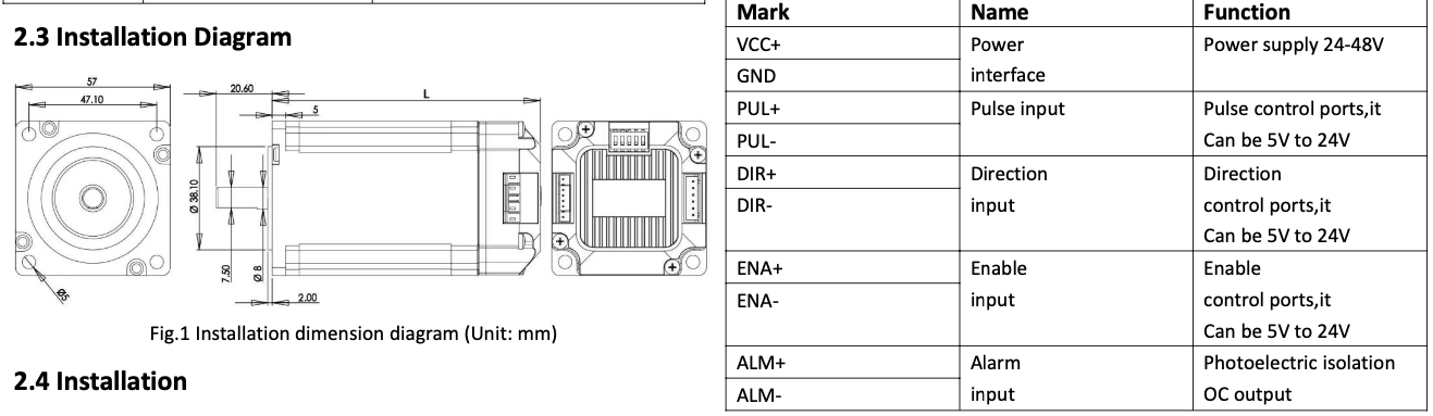
Your schematics show the stepper motor signals PUL, DIR and EN from the teensy to be 3.3V. But the specifications for the stepper you selected from Alliexpress lists them as 5-24 Volts.
Good point. Arduino boards typically use 5 V logic levels. In practice, I think that if you use 3.3 V modules, it should also work, although I have not tested it that way myself.
That is one of the drawbacks of Teensy boards: they require 3.3 V on both inputs and outputs. I chose Teensy boards at the time because they were more powerful than the Arduino boards available back then. Today, things have evolved with the latest Arduino models.
To answer your question, stepper motors have a certain tolerance and can interpret commands received at 3.3 V without any problem.
I wouldn’t count on this. I’m in the midst of a build for a different kind of scanner and in the initial prototype I picked up some cheap motors on amazon with 3.3v pulse/dir signal requirements. One of the motors turned out to be faulty so I replaced both with much better motors from StepperOnline, with 5v signals. One of those new ones would run perfectly with 3.3v, the other wouldn’t - identical model motors. Bumping the signal up to 5v fixed the problems with the motor that wouldn’t go.
Is it really wise to exceed the specified voltage ratings and use 5 V on an input designed for 3.3 V?
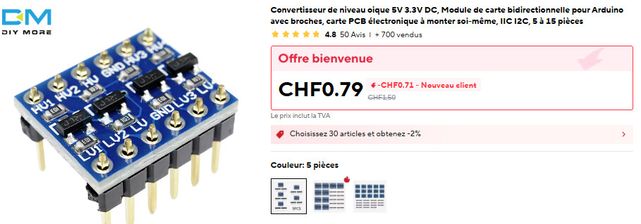
Otherwise, if @JohnSmithYou really encounters issues that I have not experienced myself, there are small bidirectional logic-level shifter modules available.
@roland these motors typically have differential inputs (opto-isolator). For logic you would be correct, but for differential inputs it would handle a range, with 3.3V been the minimum.
@JohnSmithYou The manual in the listing provides some input configurations.
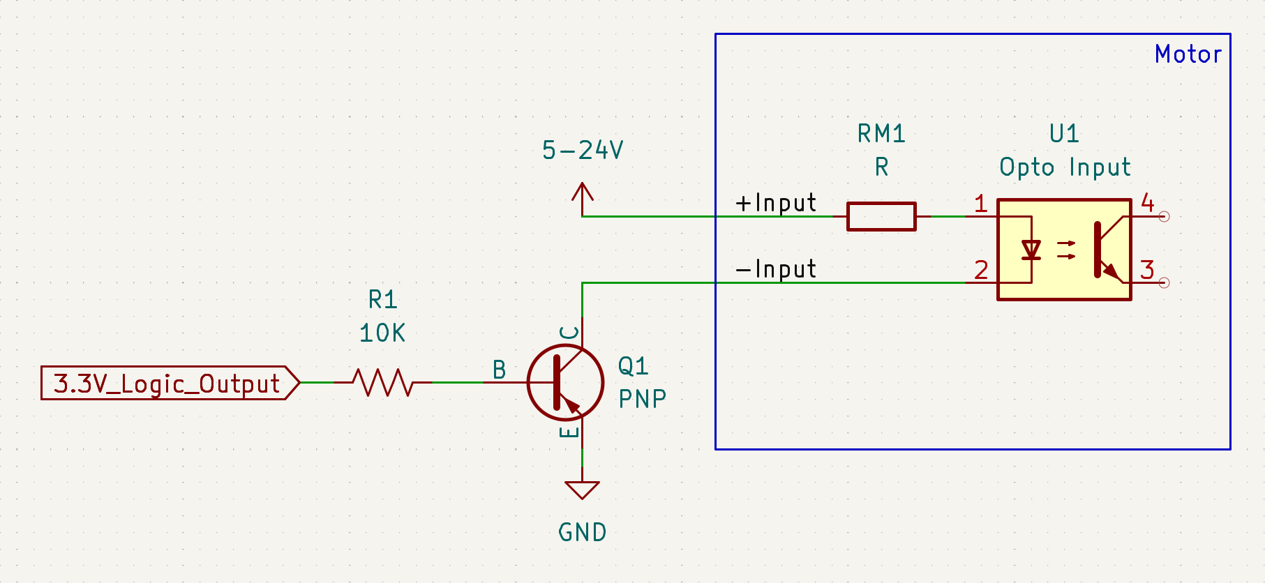
It looks like the particular motor has differential inputs with a resistor in series with the opto-isolator led/diode-side. Assuming the Vf is under 3.3V (not guaranteed), if the resistor is set to handle 5-24V the current at 3.3V may not be enough to reliably saturate the transistor-side.
Without the specs, as Perry @friolator experience illustrate, it may work, but it may not be reliable.
In general, most opto-isolators have a Vf under 3V, but with the resistor the motor-manufacturer chose to handle 5-24V, you may be operating it without enough current.
If you have generic PNP transistors (2N3906 or similar), below is another solution.
PS. There are some Teensy versions with 5V-tolerant outputs, teensy 3.2 and teensy 3.3.
In those, while the controller logic is 3.3V, the output can be configured as open-drain. If you have one of those, it can handle directly by setting the +input to 5V, and the -input to the teensy (5v tolerant) output in open-drain.
Or choose to do nothing, test it as is, see that it works perfectly well, and move on.
The motor requires 5v in my case, and the 3.3v pulse wasn’t high enough to trigger one of the motors, but worked (seemingly reliably) with the other. So there was no option but to bump it up.
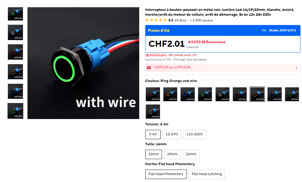
Rolland could i have please the type of push button at control panel? May be the link from alliexpess.