Omg, the newcomers bargained all your tricks already
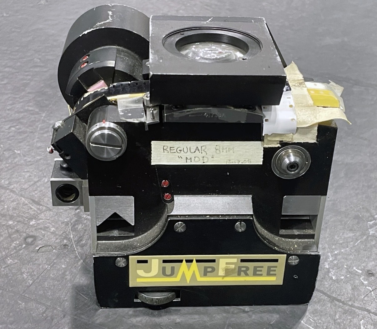
@Roland Meanwhile I’m continuing my journey of fucking up the whole system with my crazy ideas. This time it’s the gate revision and tension arm. I’ve been able to acquire 16mm gate from Cintel telecine machine that has C-mount tube milled and also has optics to collimate lights into the flat field of the gate.
I’m looking to reengineer the transport system slightly to provide more output for my light mixing box. Also I’ve noticed that freshly announced Silbersaltz Lumiere scanner has relatively simple tension arm that measures the pressure on the film and gives ability to regulate the tension so I decided to give it a try. Now the machine is off the service for quite some time until I confirm that my ideas were legit.
The reason? I’ve noticed that with some stocks that are bent along center axis I’m not able to fine tune the focus plane to have 100% sharpness both in the center of the frame and in the corners. Which started new adventure to find out if your frame can handle alternative gate system. I’m on my way - hopefully I’ll report with success in couple of weeks.
P.S. Thank you for the “Roland’s Wet Gate” .stl files. I was tempting to ask but was shy enough. I’m already printing em.
I have never encountered this problem of lack of sharpness and inability to achieve focus with film gauges between 4.75 and 16 mm. I always make sure to work with a well-stopped-down aperture in order to increase depth of field. However, this requires a very high light intensity (4 × 10 W). It is also important to pay attention to the lateral clamping force, which accentuates the “bowing” effect.
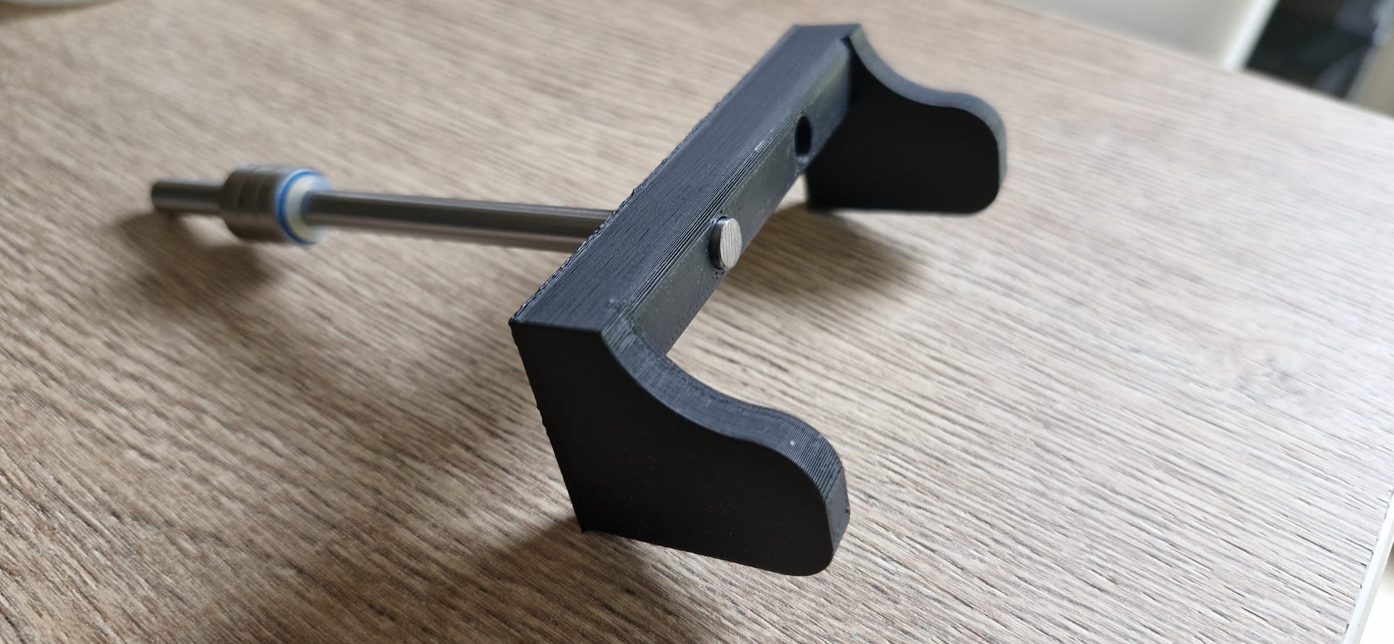
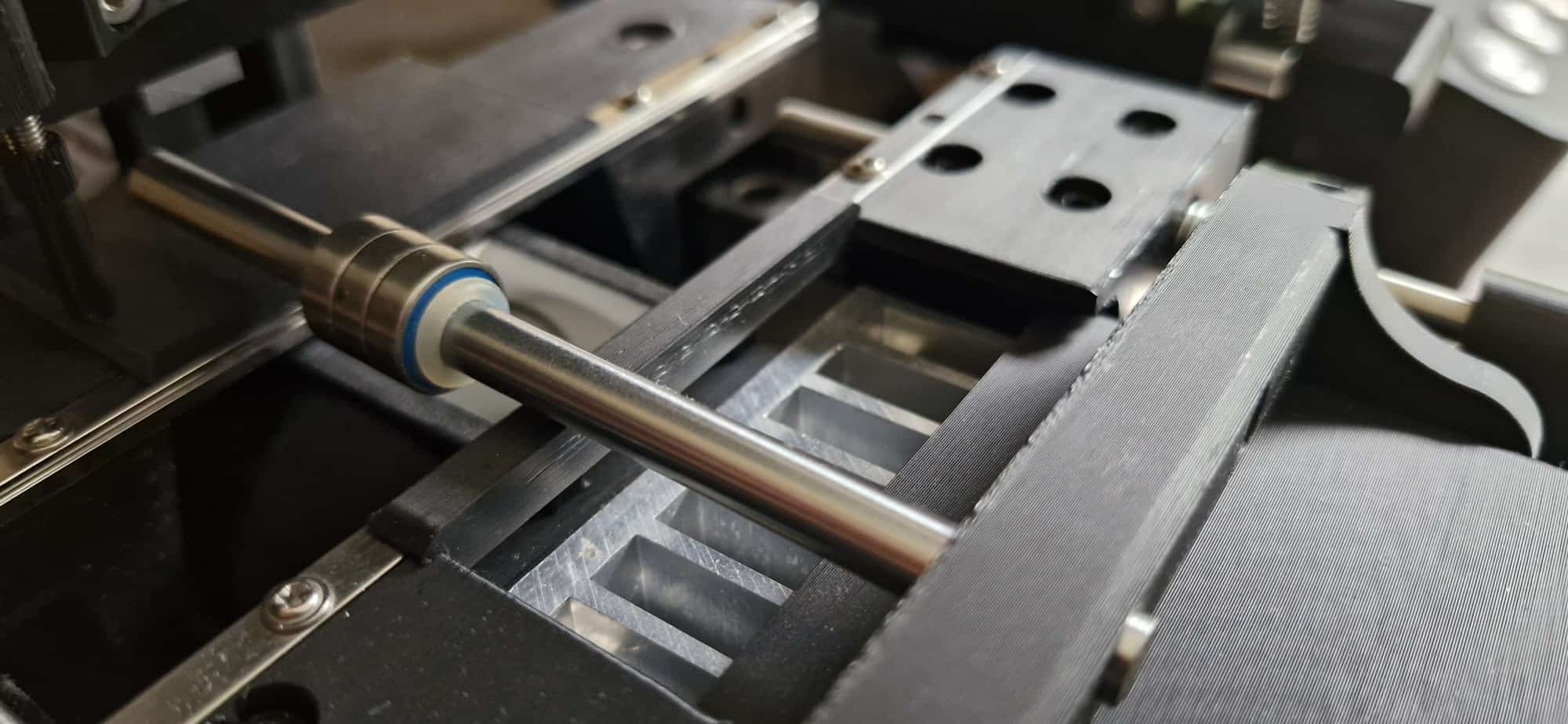
With 35 mm film, however, this problem can arise. I therefore made a small pressure plate whose simple weight was enough to flatten the film.
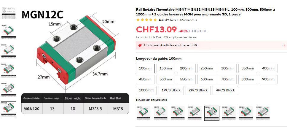
In summary, for those who may not clearly visualize the process: the film is guided by the MGM5 rails along the entire length of the pressure plate. Before the gate, a metal shaft applies pressure by its own weight to the top of the image and flattens it. When I designed this part, I had thought I would need one shaft before the image and another after it. In my case, a single shaft was enough.
@roland Such a clever design trick, I’ll probably design similar assembly to test the difference. I do have enough light to stop down the aperture on my BW gate (white light, 40W equivalent) but with new narrowband ECN gate it’s becomes harder and I’m operating with slightly less powerful output.
Anyways I’m just curious person and testing things myself to get to the point where I’m confident in result and repeatability. Also I’m adding color touchscreen display just to make it look fancier)
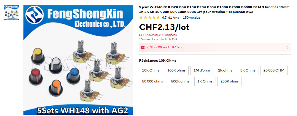
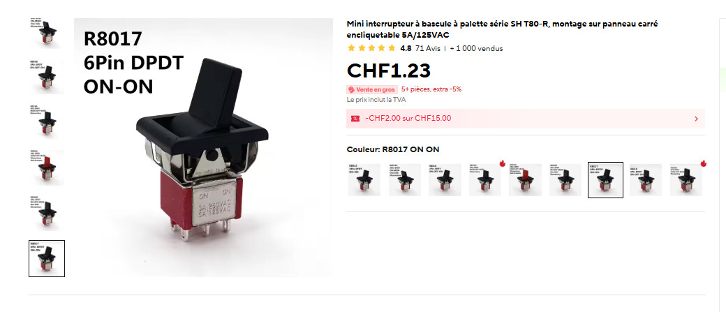
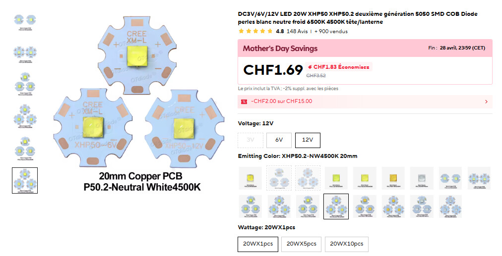
Roland I would like to know the type for some of the components that are not in the drawings. 1) the potentiometers in the control box. 2) the switches in the control box. 3) the type of the LED lighting 4) the heatsink for the LED. 5) the type of the mosfet flash (led driver). 6) the type of the BAUMER laser, especially if it is NPN or PNP. 7) the type of Linear Rail Carriage at the Potence eclatee.
Also if you can find the file for 3D-printed bracket to connect parts 2 and 3 movement of the camera will be usefull.
I have started printing the parts with ASA printing material which gives an excellent result. I’ve also ordered most of the stuff and I’m also looking into whether to use the same one lens that Rolland uses or the Schneider-kreuznach app-component hm mc 4.0/45mm, or try the TTArtisan APS-C 40mm F2.8 MACRO. As a camera, I want to get the same one as Rolland’s for compatibility without conversions in the capture program. I am waiting for some clarifications from Rolland about some components as well as the program for the full operation of the scanner. Also after the completion of construction I am thinking about some minor improvements. I am in the process of construction.
Heat sink 58 × 58 × 30 mm. I couldn’t find any more on AliExpress, so I think we’ll have to go with a 60 × 60 × 20 instead; the size shouldn’t be a problem. Mine always stays cold, even after intensive use. However, the diodes should not be left on continuously, as in that case the heating on the plastic side becomes too significant. I left gaps between the heat sink and the plastic to allow air to circulate.
Laser: PNP or NPN doesn’t make much difference, but choose PNP.
No, sorry, it’s gone. But if you’re having trouble drawing such a simple part yourself, I have to wonder. It’s a cube with 4 holes on 2 faces and a chamfer that’s only there to save material and, incidentally, for aesthetics. And once you’ve drawn it, make it available to the other users :-).
You won’t be able to put TTArtisan as it’s designed for APSC sensor and has different mount. Most of the industrial cameras have C-mount so the lens should be appropriate. Schneider lenses aren’t cheap, but you can get any enlarger lens and use it. Nikkor EL series are affordable and won’t make such a difference with APOs. I’ve used cheap 50mm lens on M39 mount successfully here.
Yes I know. And I agree with your thoughts. But TTArtiscan m43 MFT mount with adapter to c mount may be it is a cheap but reliable solution for 1-1.1 " sensor with some interesting features e.x macro. Just as a thought because I know exist many difficulties with mount distance. Also i have test nikkor 50 m39 with good results. But first i will use the Schneider Lens.