See the photos already provided above.
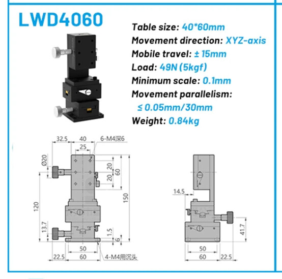
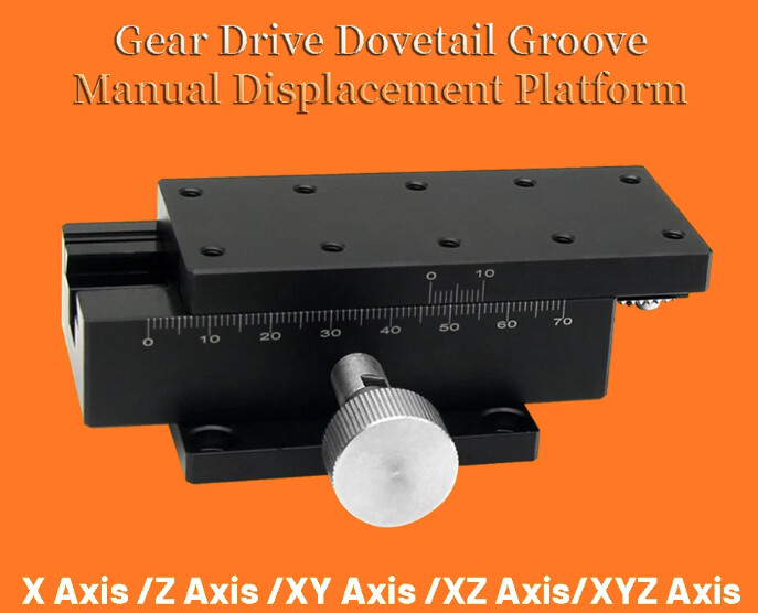
Part no. 1: 1 x 90 x 40 mm, for the forward/backward movement of the camera.
Part no. 2: 1 x 90 x 40 mm, for the vertical movement of the camera (fast but not very precise movement).
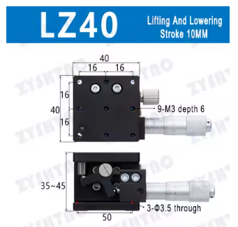
Part no. 3: 1 x 40 x 40 mm, for the vertical movement of the camera (limited travel, but precise for focusing).
To connect parts 2 and 3, there is a 3D-printed bracket. It is not a complicated part. The problem is that I can no longer find either the drawing or the .stl file. Please let me know if it would be impossible for you to design it yourselves.
Then, underneath this “support arm,” there is the lens mounting assembly. Why make it so complicated?
Because even the slightest movement or vibration, however small, causes either image movement during capture or, in the worst case, a loss of sharpness.
This part of the mechanism has two advantages. The first, as I mentioned, is to prevent vibrations. The second is to stiffen the aluminum profiles, which are still 60 cm long.
I realized, while adjusting the focus without these parts, that simply resting my wrist on the upper profile in order to adjust the focus caused the profile to bend by a few tenths of a millimeter, which altered my setting.
Once the clamping screw is loosened, this system allows the camera to be moved freely forward and backward, and up and down, while also allowing the zoom to be adjusted freely. Once the desired camera position has been chosen, all that remains is to tighten the small knob located on the right side of the lens.
I know these parts have a certain cost; it is up to you to decide whether you can do without them.
The upper and lower parts are bonded together using cyanoacrylate glue.
A spring must also be inserted between the two “jaws.” These must gently brush against the film, not clamp it.
This part must be used exclusively with lens-cleaning cloths, folded several times and moistened beforehand with isopropyl alcohol.
Essuie film antipoussière.stl (317.0 KB)
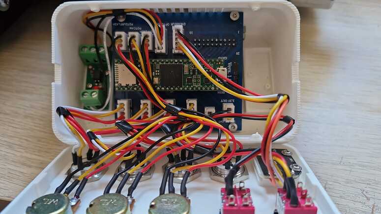
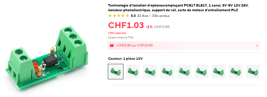
L’optocoupleur qui fonctionne de 3 à 5 v.