Do you have a pdf or any file that lists the parts needed for the construction of the film gate guides/rails?
I don’t really understand your question. Yes, I stabilize the perforations using the capture software and then in DaVinci Resolve. But the scanner already produces images that don’t jump around all over the place.
Do you have a 3D printer that would let you print these parts?
Creating a PDF with a parts list including the dimensions, and attaching the printable files, is a lot of work. I’m looking for another, simpler solution for me.
Maybe a single .stl file with all the parts for one module. Then the user would select the parts to print and also be able to calculate the dimensions of the parts to buy. I’m looking into that.
Dear Roland,
I’m finally at the point where I can confirm full operational status of my copy of your machine. Took me a while, learned alot. It wouldn’t be possible without your help, so God bless you.
Already doing updates, ordered a bunch of different LEDs, with intention to build narrowband mixing box. Also looking for updated transport system and improvements in software. Fortunately AI helps with coding significantly and scanner operates on custom designed application.
5 Likes
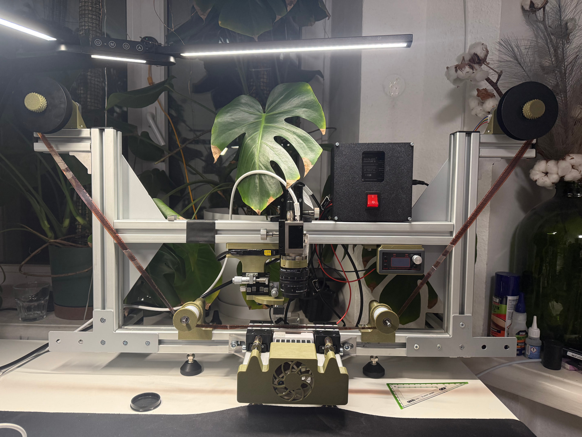
I’m really pleased to see that your project has come together, and just as glad to see that you adapted the scanner’s operation to match your own ideas.
Your way of handling the triggering of the flashes and the camera through a Basler system seems like an excellent approach to me.
Please keep sharing the improvements and modifications you’ve made — I’d love to read more about them. ![]()
1 Like
After repairing the projector electronics and audio, while the audio works, it unfortunately is picking up nearby radio stations. I ordered the amplifier based on the TA7668.
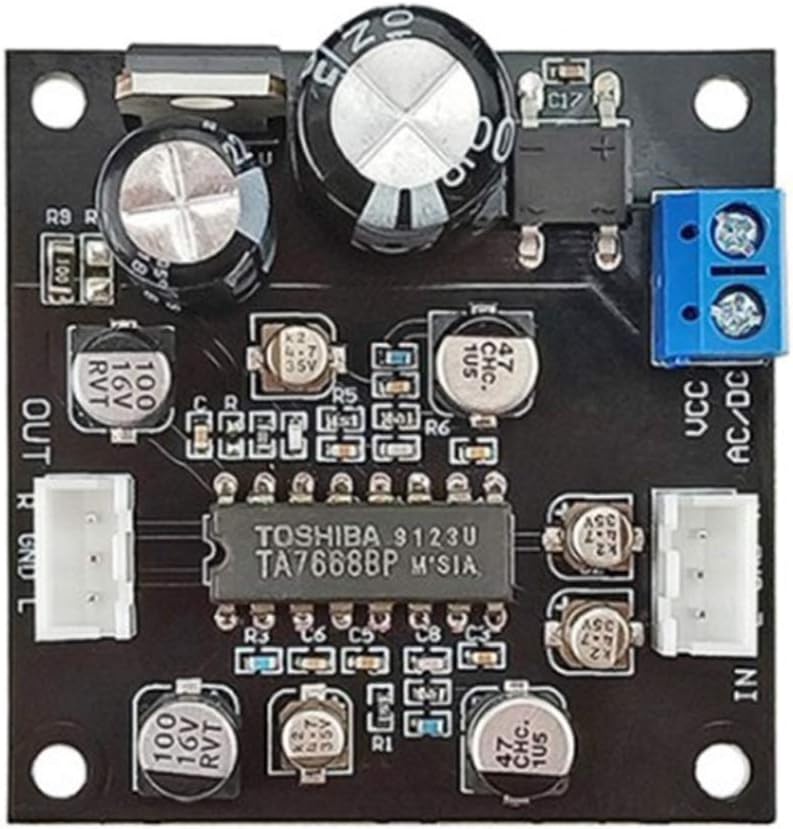
From the initial testing it certainly works better than the old electronics.
Note that the output level is suitable for a small headphone (about line-level).
When using the amplifier, please note that the two wires connected to the audio head will go to the audio input GND and R (or L). The floating wire shield can be grounded to the power supply, but do not connect it the input GND.
Thank you for this information. In my first attempts, I had two problems at once: an amplifier board that wasn’t working and the sound head I took from a projector wasn’t working properly either. That made it quite difficult to get my homemade setup to work even roughly. I managed to get a few noises out of it, somewhere between the vague monologue of a drunk man and the mooing of a cow giving birth.
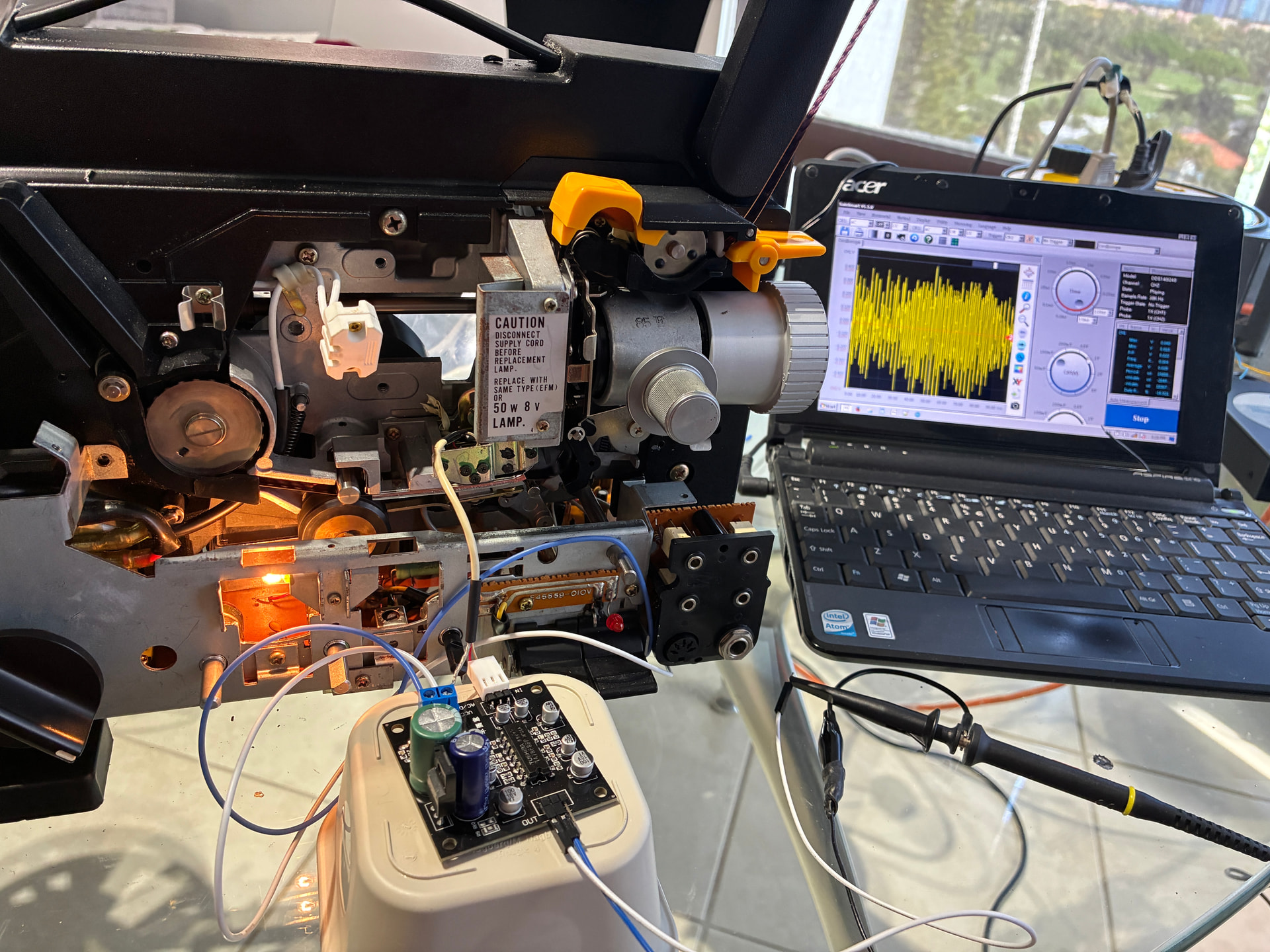
On the other hand, the idea of testing directly on the projector is excellent. It removes the head-positioning issues and will let me focus on the amplification first. As for the interference problem, I’ve already been able to hear that the stepper motors produce noise, and that will probably be difficult to solve, but I’m not at that stage yet.
And since I’m in the middle of moving house, I’ll have to take a forced break, but I’ll come back to it.
Many thanks for your valuable advice.
1 Like
There’s always the transmission line solution that the radio folks use: put everything in a metal box, including the wires!
If you used 75-ohm terminated, shielded coax (say, RCA cables) running between all PCBs (which should also be in their own metal boxes), that sort of interference should disappear more or less completely. You just need an extra 6dB (or 2.0x or 2V/V) gain op-amp after each terminated signal to bring it back up since properly terminating the transmission line cuts the voltage in half.
I would have liked to have heard that! ![]()
I should have been able to get the old electronics a bit better, but it is time consuming without an schematic. And don’t want to remove the heads to replace the wire, to avoid alignment issues.
So at the end the new board is better and small enough to fit near the heads. And yes, a metal box is part of the plan!
1 Like