I need your advice on creating a “Sound Capture for Super 8” module.
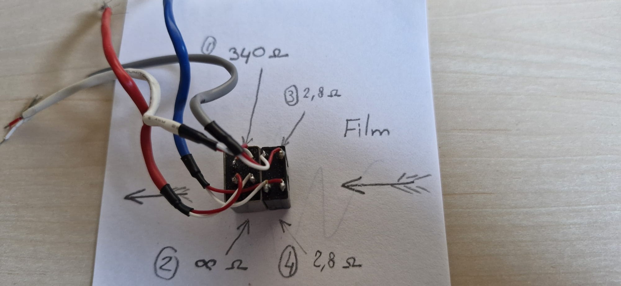
This module is intended to be inserted to the right of the pressure plate, but for now I’m trying to understand how to wire up a sound head salvaged from a Sankyo (either a 700 or an 800 stereo—I can’t remember which). In the photo, you can clearly see that I have an erase head that won’t be of any use to me, but I think I’ll keep it because it’s glued to the playback head.
This playback head has two tracks: the main track and the balance track.
The first problem is that the balance track has infinite resistance, whereas the main track measures about 340 ohms. Is that normal? I have serious doubts.
Also, what would you recommend for the preamp, and how can I output to a USB connector? I have no idea at the moment. Thanks in advance!
The narrower track would be expected to have a higher impedance, but I do not believe it would be open. Try changing the scale of the multimeter to 10K Ohm range and see if it still shows as open.
This post has some information that may be helpful. There are DIY boards for that purpose also (TA7668 mentioned in the post)
For testing, another route may be using a tape player just as preamp.
I can confirm that the resistance is infinite at the compensation track head.
I’m afraid it may be damaged, but since the measurement is taken directly across the two terminals, I’m wondering what could actually cause a read head to stop working.
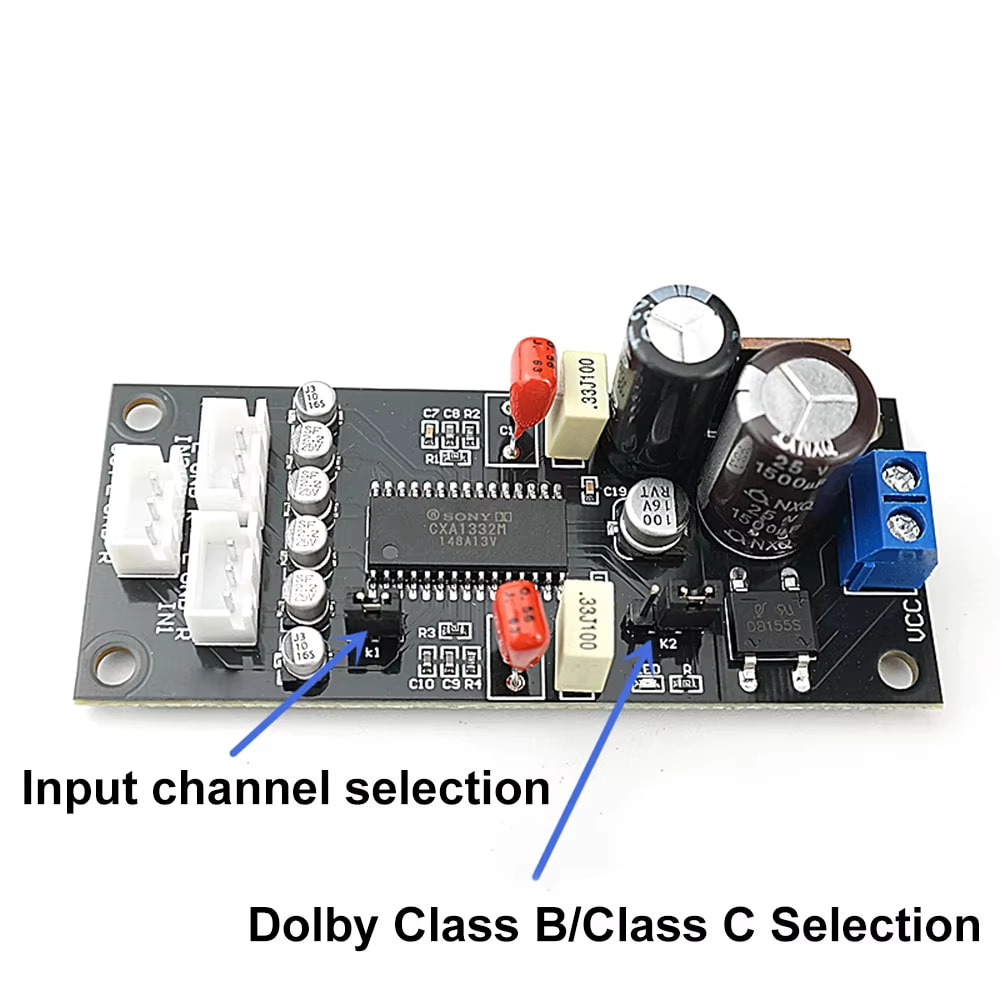
I found one of these amplifier circuits on AliExpress. Do you think it’s the right one?
Alright, we’ll test it. The electronics have been ordered.
But the guidance precision needed to read the audio tracks scares me a bit.
Such tiny audio tracks must tolerate pressure and speed variations very poorly.
There’s work ahead.
I wonder what methods the pro scanners use — I doubt they take apart old projectors to salvage the playback heads
I was researching options to Super-8 heads, and it looks feasible to use a reel-to-reel 1/4 inch tape mono head (main stripe only). In looking for alternatives, came across this blast from the past internet find with much info on all kinds of magnetic heads.
A poor-man alternative may be to use the 1/4 mono head for the main stripe, and a stereo cassette head (using only one track) for the balance stripe.
I’m going to start with a project using my Super 8 sound head, and then we’ll see if I can at least get some audio out of it.
Maybe others are starting from more modern electronic components that could detect variations in magnetic fields. I can’t really imagine modern scanner manufacturers drawing from old stock or having magnetic heads remanufactured at great expense.
There might be a more up-to-date solution, but I don’t know if that’s the case, and I don’t know what it would be…
Heads can be manufactured in small batches. It’s a specialized skill, but it’s not that exotic a thing that one couldn’t manufacture their own. The only modern film scanner manufacturers that offer magnetic audio capture that I can think of are:
Lasergraphics
Film Fabriek
I don’t know what Film Fabriek does for theirs.
I know a bit about the Lasergraphics head because we own two (8mm and 16mm). They are custom designed and manufactured in small batches, and they will make one for you for specialized formats but it’s very expensive (for example, 3, 4, 6 track full coat mag - the tape is the same width in all three cases but the track positions vary. On our MTE dubber, we have heads for each of those - they’re modular plug-in units.)
BMD Cintel doesn’t do mag. Xena relies on the original Rank Cintel mag readers since it’s a modded Cintel machine at its core. Arriscan and Scanity can only do optical, I believe. DFT (Scanity/Polar scanners) also own Sondor, which makes high end sound capture hardware. I believe they push you towards buying a Sondor machine for mag audio, rather than integrating into their scanner. but I could be wrong on that.
In fact, Cintel reads digital audio only for 16mm films.
MWA also has scanners equipped with magnetic heads for 8mm and 16mm.
In the end, scanners fitted with a magnetic head aren’t that rare.
I think some of them don’t ensure synchronization with the images; you probably have to do two passes—one for the images and another for the audio—but I’m not completely sure either.
I think I’m going to go in that direction instead. Because with a magnetic audio capture, if your film breaks or any other issue prevents continuous capture, it becomes problematic. And also because re-synchronizing the images with the sound isn’t really a big problem as long as the speed fluctuations of your devices remain low.
Maybe a completely separate module allowing precise positioning of the playback head should be considered—perhaps, as Friolator was saying, with interchangeable heads…
The first step of a project is always steeped in dreams…
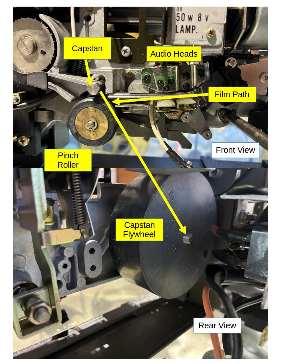
I am fixing a Sanyo Sound 500 and while it is naked, took the opportunity to make some notes on the audio mechanics. The Capstan Flywheel is massive!
Sharing the notes in case is helpful.
Thanks for the illustration Pablo . I also repair projectors, and the capstan is always more or less the same. The film passes between the metal shaft and the rubber roller, so there’s inevitably some slippage on the metal-shaft side—especially when the projector starts up… That might help reassure those who are always worried about scratching their film.
A quick update on the progress of my tests: I’m not getting any sound, either with the original head or with the magnetic heads from AliExpress. Nothing. I think the amp may not be working, or the input signal is too weak. So for now, it’s a total failure. But I’m still looking…
I had the same thought… there is a lot of contact between the film and the mechanics around the audio heads.
Sorry to hear that. The problem on the projector that I am fixing is the electronics, and already ordered the parts. Will be able to do some testing after they arrive.
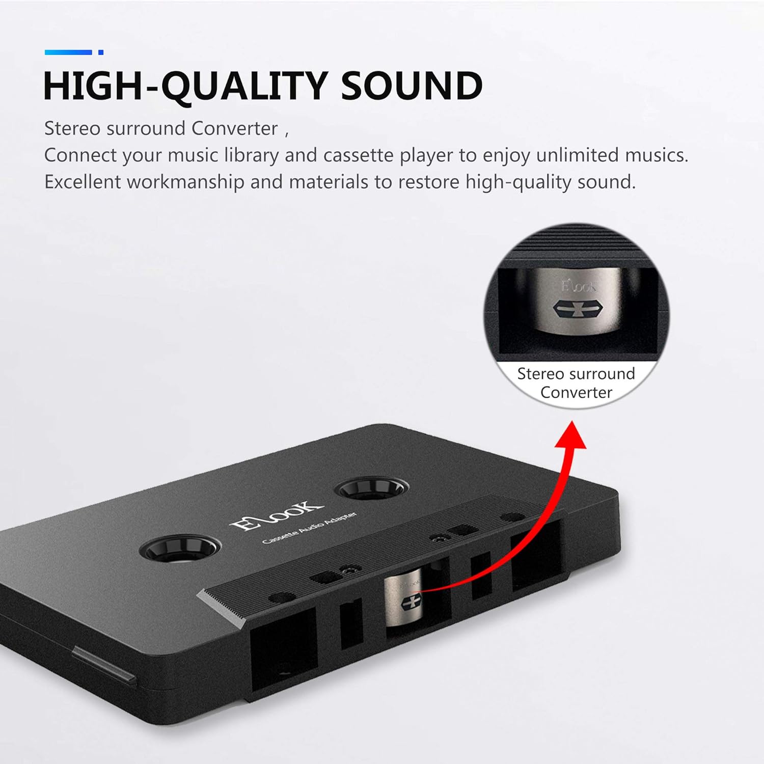
One way to test a magnetic head and amplifier may be is using one of those cassettes adapters with an audio source… kind of a magnetic tape simulator.
I understand the principle — it’s an idea. I still need to do more testing and possibly try another amplifier. But right now I don’t really have the time… thanks for your reply.
@Roland Thank you so much for sharing the details for your build! It is so cleverly thought out. I have a couple of questions: first: how do you deal with the film tension, so that the feed and pickup motors compensate for the radius of the film as it unspools? Second question: is the film guide enough to keep the film flat during digitizing?
Hi and welcome to this forum — I hope you’ll find the answers to your questions here.
The user chooses the number of frames per second at which they want the film to advance.
Each time the laser detects a perforation, a counter is incremented.
Twice per second, the Arduino script adjusts the motor speed so that the number of perforations detected matches the frame rate chosen by the user, from the start to the end of the reel. You’ll find earlier in this thread the Arduino script that does this. There’s also a whole calculation that smooths the corrections based on the error range, to avoid sudden acceleration and braking, and to maintain a steady speed.
Because the film is guided over a long distance by lateral grooves, flatness in the direction of travel isn’t an issue.
For lateral curling up to 16mm, there’s no problem. If a film is curled, the strong lighting makes it possible to stop down the lens and increase depth of field. So there are truly no concerns.
However, for 35mm, rare films were too distorted (curled). I had to make a small frame, and four ball bearings press on the film before and after the frame. That solved the problem.
@Roland Merci beaucoup! Thanks for the reply. I’m in the very early stages of planning, before I venture into the actual construction of a film digitizer. I find your design to be incredibly flexible. How much image stabilization are you doing in post?