I’ve been reading this thread intently for the past few weeks. What a fantastic system you’ve created! Relatively simple construction, modular, and with clever solutions for film guidance and control. This design has inspired me to replace my own machine, which has been gathering dust for several years now. About 10 years ago, I converted a Eumig MK8 in a way that is well documented by Frank Vine (cine2digits) and Freddy van de Putte (VideoFred). In that time I’ve also purchased Frank’s lighting system for this purpose. With this system, I was able to digitize and edit family recordings in Avisynth, using (slightly modified) scripts from Freddy, to my complete satisfaction.
Recently, I’ve been exploring ways to get the lighting system working again. The original software that came with it is based on Windows 7 and wouldn’t run on my current systems. I’ve now got everything working again (temporarily).
In the coming period, I want to start building a system based on the setup you designed, transferring the lighting system and camera from the old setup.
I’ll gratefully use the knowledge you’ve already shared, I hope to gain more insight into the choices you made and the reasons behind them.
Roland, congratulations again on your design. Can you share more information about the motors that you are using? Understand they have built-in drivers, so I would like to understand how many steps per turn setting you are currently using for stop-motion. Thanks
I’m using Nema23 motors, 8 mm shaft, 57-100, 2.5 N·m.
For the motor that drives the film, I’m set to 6400 steps per revolution.
The other motor is set to 3200 steps per revolution, to get a faster rewind speed.
I was so happy to read that you’ve confirmed stop-motion possibility with current machine design. At some point in the future I’ll be there too. From day one of my journey in development I knew that your machine is capable of everything and you’re proving it constantly.
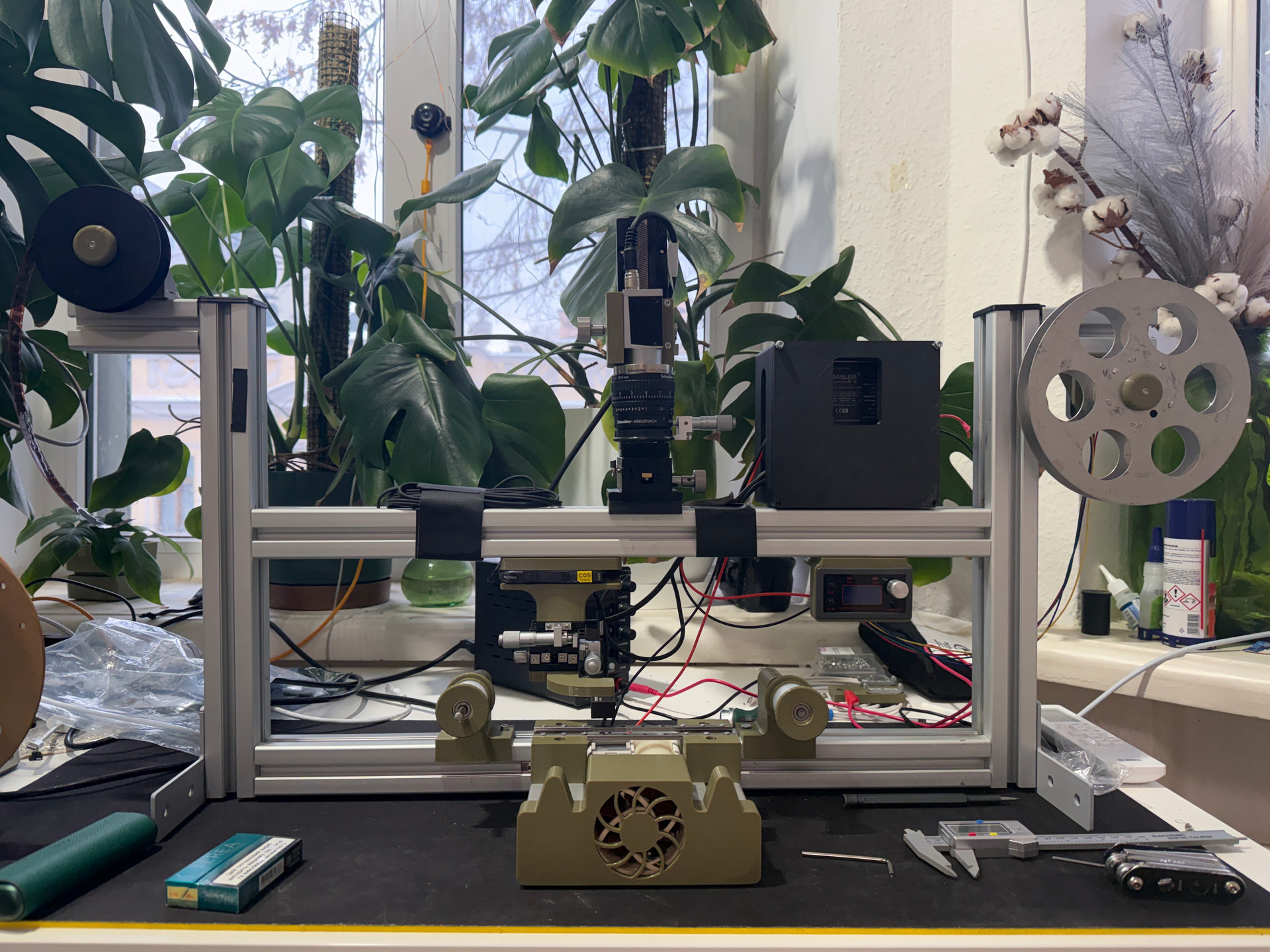
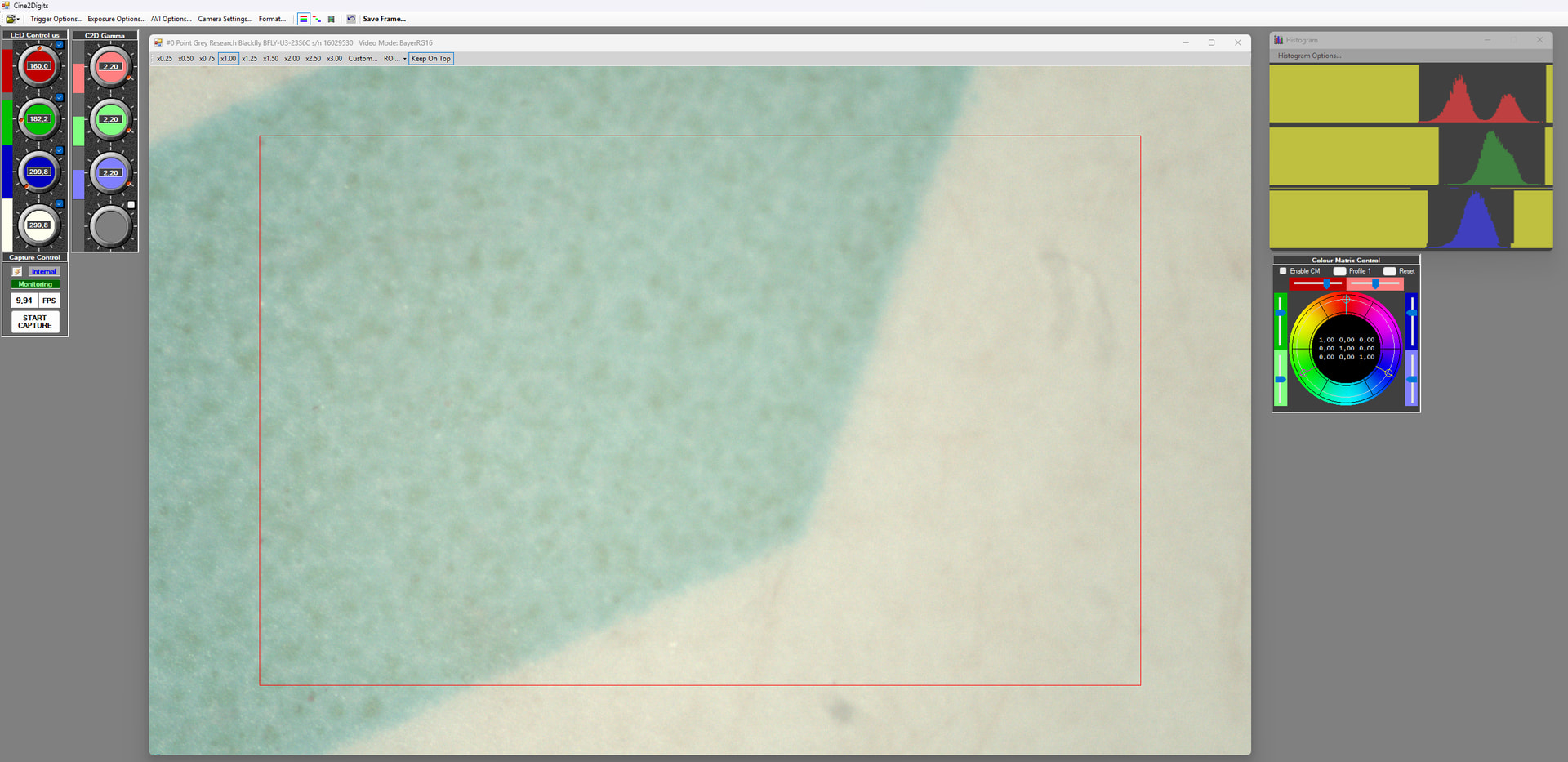
Meanwhile my assembly is slowly getting better. Finally I’ve purchased APO Componon 40/2.8 and acquired new Basler camera that suits my resolution needs. Still looks messy, but at least I’ve added temporal distro-box to clean up internal commutation.
Now my machine works dumb → just the right motor constant pull (speed is adjusted on controller), laser triggers first edge of each perf and signals camera to take a shot (through SLP controller). Works great even in current state, capable of scanning my films already.
My next step is fixing the tolerances, stability of the frame/camera and designing new light block with RGB light (has accurate LED fixtures).
Then I’ll switch onto microcontroller for drive based on your design, and my final goal is to do three exposure captures (separate dye monochrome density shots) to mimic ARRISCAN / LaserGraphics approach. Will take years I guess with my current speed, but occasionally I’ll be there.
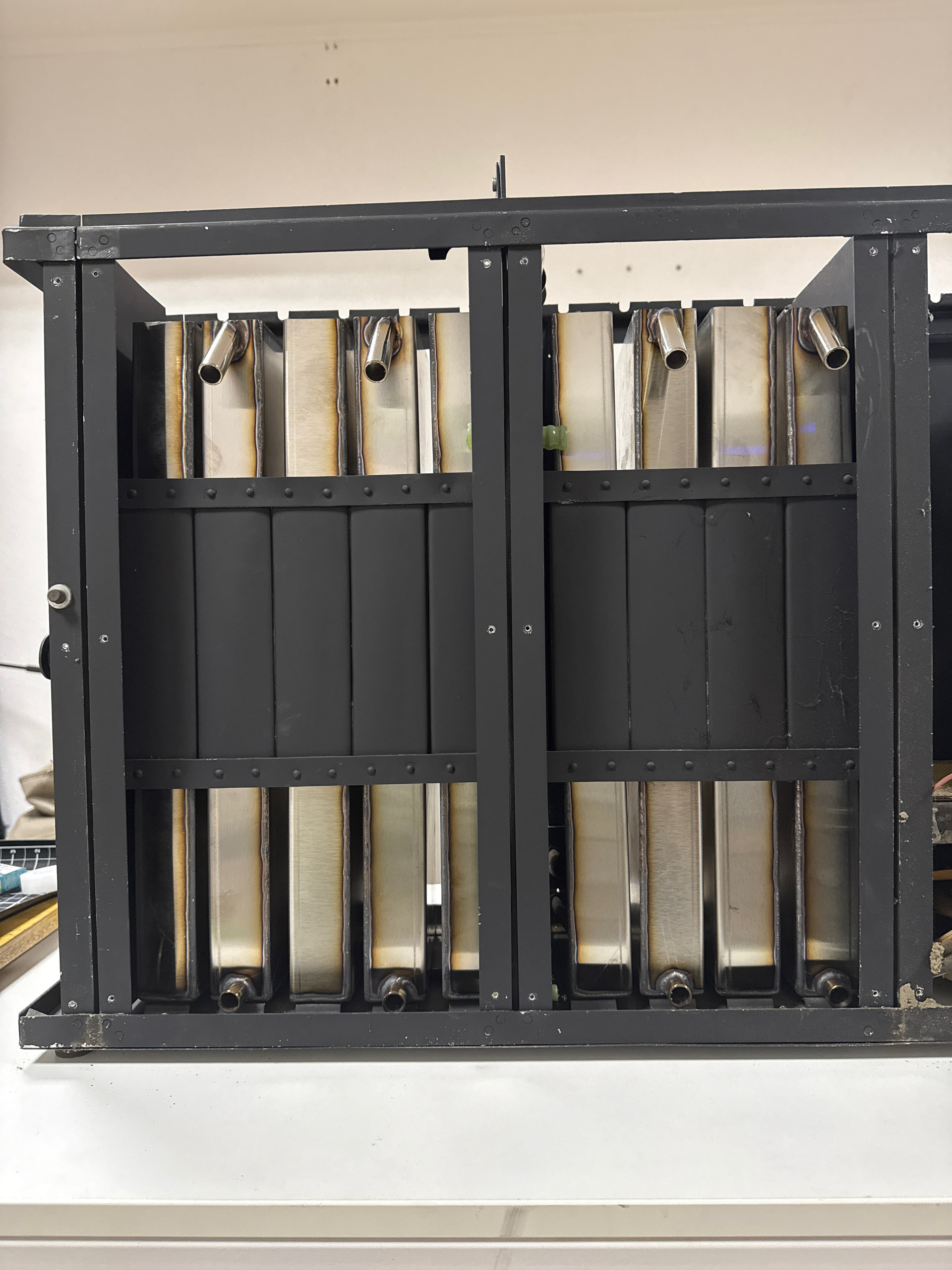
p.s. I’m also half way into film processing machine, which should be up and running by Spring 26. Attached the base frame)
I’m really happy to see your machine is coming along. Congratulations on your work.
Also for your other development project.
These aren’t criticisms, just curiosity, but I do have a small question about the very large distance between your camera and the film. I’m also thinking that if the distance is that large, it could generate vibrations that affect the stability of your images. To improve stability, you absolutely need to eliminate any mechanical play and decouple the motors from the chassis as much as possible by adding rubber isolators (silent blocks). Also regarding the camera/film distance, can you tell me what resolution you’re achieving? Is it for 35mm format?
I also notice you don’t have any springs pressing the film laterally toward the back of the scanner; that can also cause the image to float.
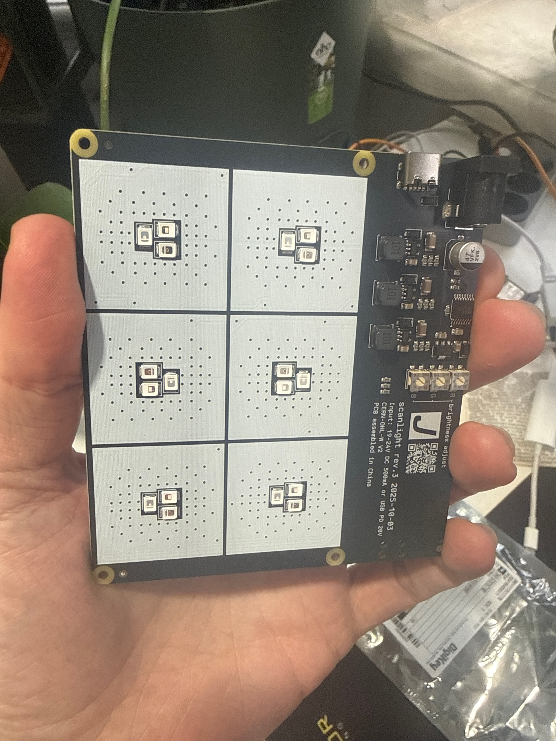
The printed circuit board in the photo also interests me—are you planning to use it on the scanner ?
Keep going, and don’t hesitate to ask me if you need any information if you run into problems.
The large distance is because I’ve just got a new lens with helicoid adapter which is significantly shorter. I was using 3d printed assembly previously, which is not working with new camera/lens setup. I’m on it now, the lens would be much closer to the film plane after I design the new fixture.
There is no springs as I’m waiting for a new set of MGN12 rails from AliExpress, my previous order was lost unfortunately so it takes them too long to arrive.
For the chassis isolation - it’s a great advice, wasn’t thinking about that at all. Makes total sense. I’m using NEMA17, much smaller drives and they provided manageable wiggle, but it’s a great idea to decouple them anyways. Overall it’s still a huge amount of points in my design where mechanical play could be present, so now I’m focusing on this issue. As we’re having constant blackouts here in Kyiv printing something that requires 4-5 hours becomes a challenge, so things are not moving fast enough. Once I fix all the joints and enforce the frame I’ll show you the results.
New camera resolution is 4096 by 2160, so the frame resolution on 16mm film should be better (not tested yet). On my previous camera I had only 1440x1080 (Frame.io)
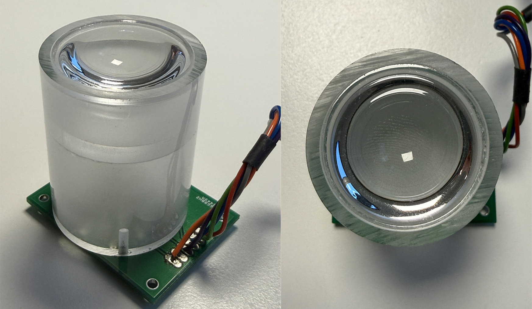
The lighting fixture was purchased here ( scanlight v3 info | jackw01 ), it’s slightly bigger than 100mm distance in your design, but I really want to fit this one into the scanner instead of cheap low powered LED’s I’m using now. I’ve been scanning 35mm film (stills) for years and know that even slight difference provides huge color shifts that can’t be fixed in post.
I’m a cinematographer and purist in terms of the actual color reproduction so want to make sure that there is exact wavelength for the film stock is used and I can convert raw sensor data into Cineon color space to match professional scanners used in the industry.
Thanks for this info. LED control sounds really interesting to me, but I only capture in continuous mode, not in Stop Motion. And for this mode you need a lot of light output in order to reduce the exposure time as much as possible and get the sharpest image possible.
On my setup, I use 4x 10W LEDs (which can sound scary :-)) in FlashScan mode so they don’t overheat too much. That lets me use exposure times from 30 µs up to 400 µs max, depending on the film of course. You can never have too much power available, and as a bonus you can stop down the aperture to its optimal value and also increase depth of field.
So I’m not as much of a purist as you when it comes to color processing. I mostly trust my camera’s white balance, and then I do the corrections in DaVinci Resolve.
Sure thing, it’s just the plan for the future aspired by literal curiosity With RGB scan the actual process will slow down to 1-3 frames per second, I suppose, and will match my previous 16mm projector with stills camera (which provided 6K flat scan, 1 frame per sec).
Now I’ve basically copied your assembly (even with concave mirror in the back and 50W COB, which provides enough punch in flash mode.
Thanks again for sharing the information on the stepper that you are using, very interesting hardware.
I have a follow up question…
To confirm my understanding, when pulling 8mm film, the stepper would have a resolution of 6400 steps/turn. The spool diameter is variable. For an 8mm 50 ft reel would be ~70mm when full, ~30mm empty. A 400 ft reel diameter would be ~175 mm.
The length of the step at the gate will change proportional to the diameter.
Diameter x Pi = Circumference
Circumference / Steps per Revolution = Step Length
When the scanning starts, the diameter of the reel pulling is the smallest. When the scanner ends, it is the largest.
For example:
For a 400 ft scan of 8mm film
At the start, the reel is empty, diameter → 32mm | steps per frame = ~ 240
At the end, the reel is full, diameter → 175mm | steps per frame = ~44
Does the scanner software then uses the sprocket hole for accurate location of the frame, or the capture is later stabilized in post… or both?
I suggest a slightly different calculation. We take into account the difference in step length between an empty reel and a full reel. This is because the motor is stopped when a perforation is detected.
To make it a bit more challenging, we’ll do this calculation with a large 30 cm diameter reel, since that’s approximately the maximum diameter possible on my scanner and the inaccuracy will be greatest.
Difference in step length: Δℓ=0.1473−0.01473=0.1326 mm/step
So between the start and the end of this very large reel, we have a theoretical difference of 0.1326 mm that builds up progressively as the reel fills up.
In any case, this difference is compensated for by the real-time perforation stabilization performed by the capture software. As a reminder, we draw a frame around the perforation, and the following perforations are “stuck” to that reference position.
I’ll also add that if you scan films in 8 mm, 9.5 mm, or sometimes 16 mm, it often happens that the image is severely misframed if those films were spliced together end to end.
So the “perfect” solution would be to detect the image frame rather than the perforations, but given the diversity of films (transparent frames, blur, or images not separated by a border), I doubt I could make that system reliable.
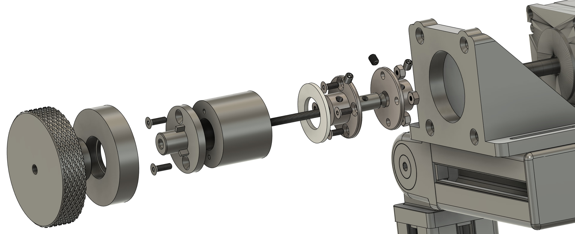
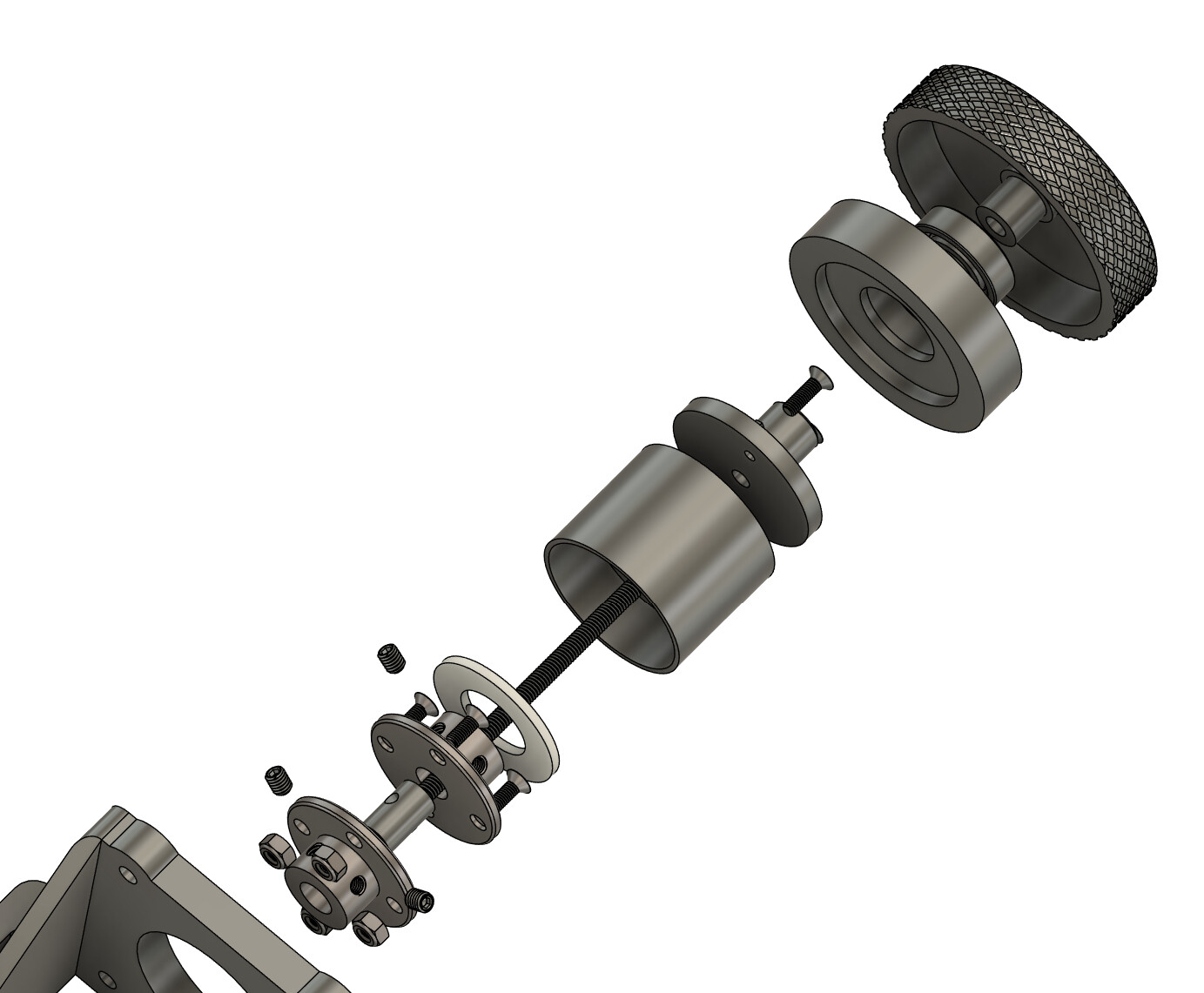
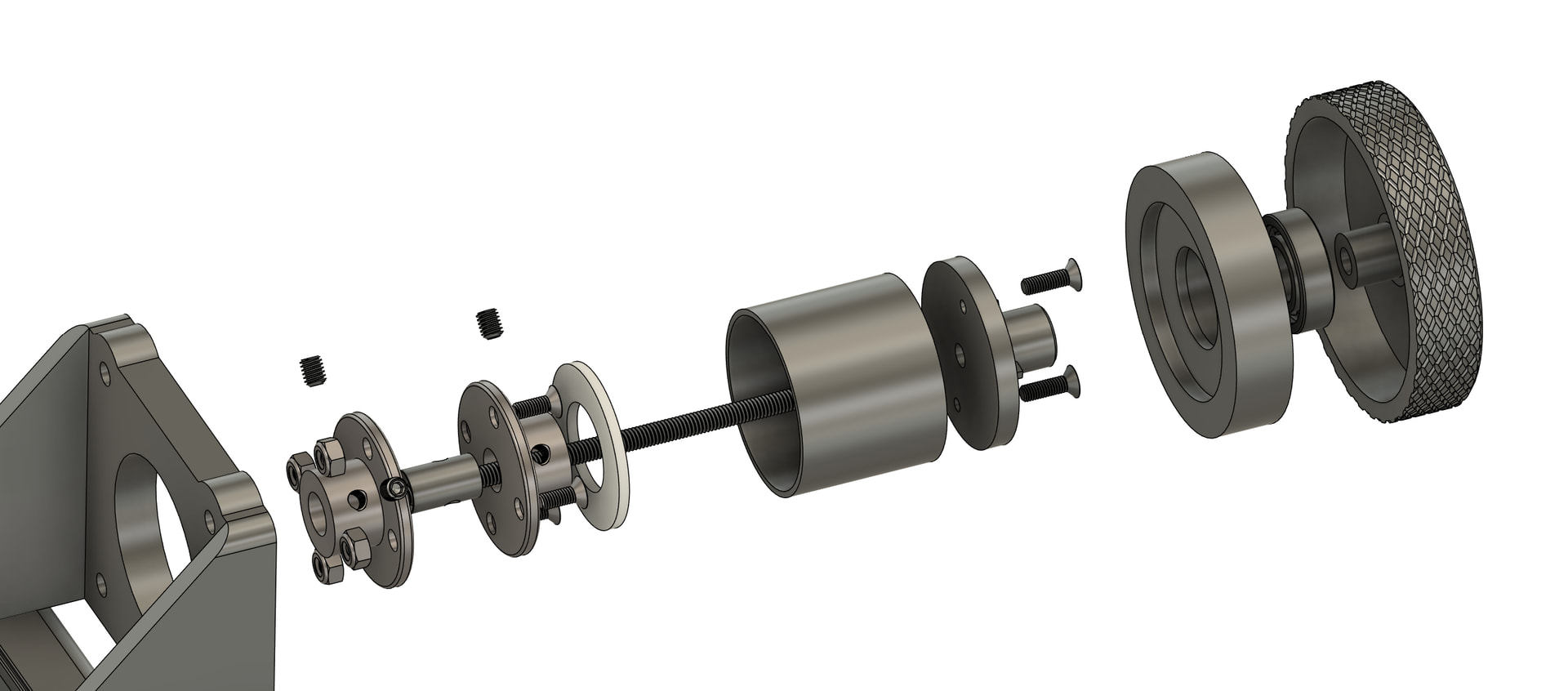
I have a question regarding the film holder mechanism you’re using on shafts. I’m designing mine based on the same coupling motor guides as you (just smaller shaft diameter), and I see that you’ve changed the fixture over time.
my assumption is that you have two screws inside changing heads that have exact distance to the gum washer on the coupler and tension makes the job after tightening the fixing block. Just curious if you ever had slippage this way (especially on the guide motor). Or I’m wrong and torque is passed to the changing heads differently?
My previous design was solely for 16mm and it worked cause there was no play in direct fixture, but I’m prepping to different heads like you and stuck with solution idea. Thx.
I’m not sure I fully understand your question (translation), so tell me if I’m completely off. I don’t have any slippage—even with 16mm reels, the clamping force is enough.
To prevent the tightening knob from unscrewing, I designed it in two parts, and the part that presses on the reel is not mechanically linked to the tightening knob. I’m attaching drawings that may illustrate my explanation more clearly.
You’ve nailed it perfectly. Thanks again for having such a detailed breakdown of parts. I was thinking that you’re having screws as a pressure mechanism, but now it’s totally clear. Thank you again for this, solved all the questions
With several ordered components for the frame and a fiber optic detector on the way, I’ve been focusing on getting the Cine2digit/HS-CFLed system working again.
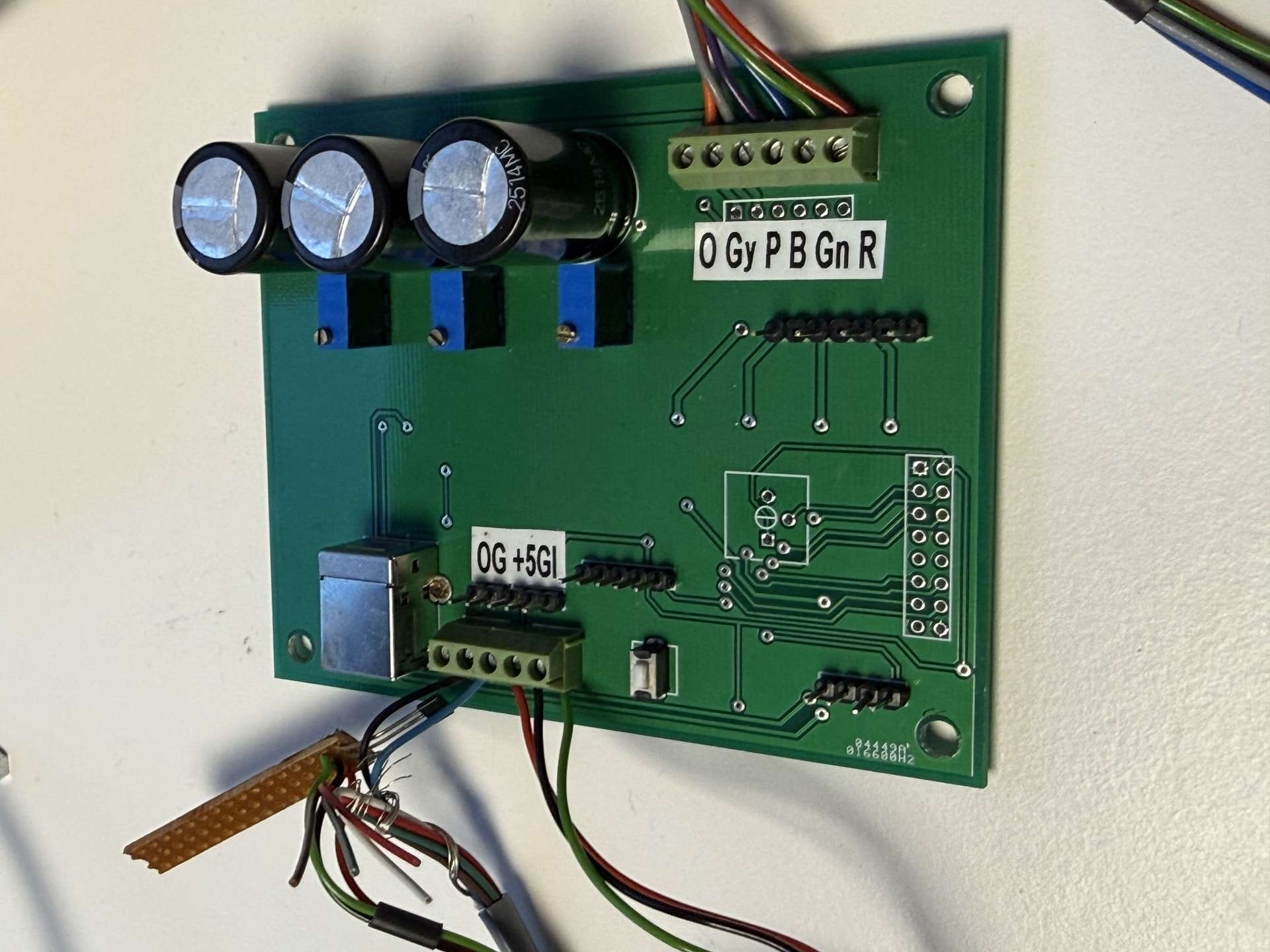
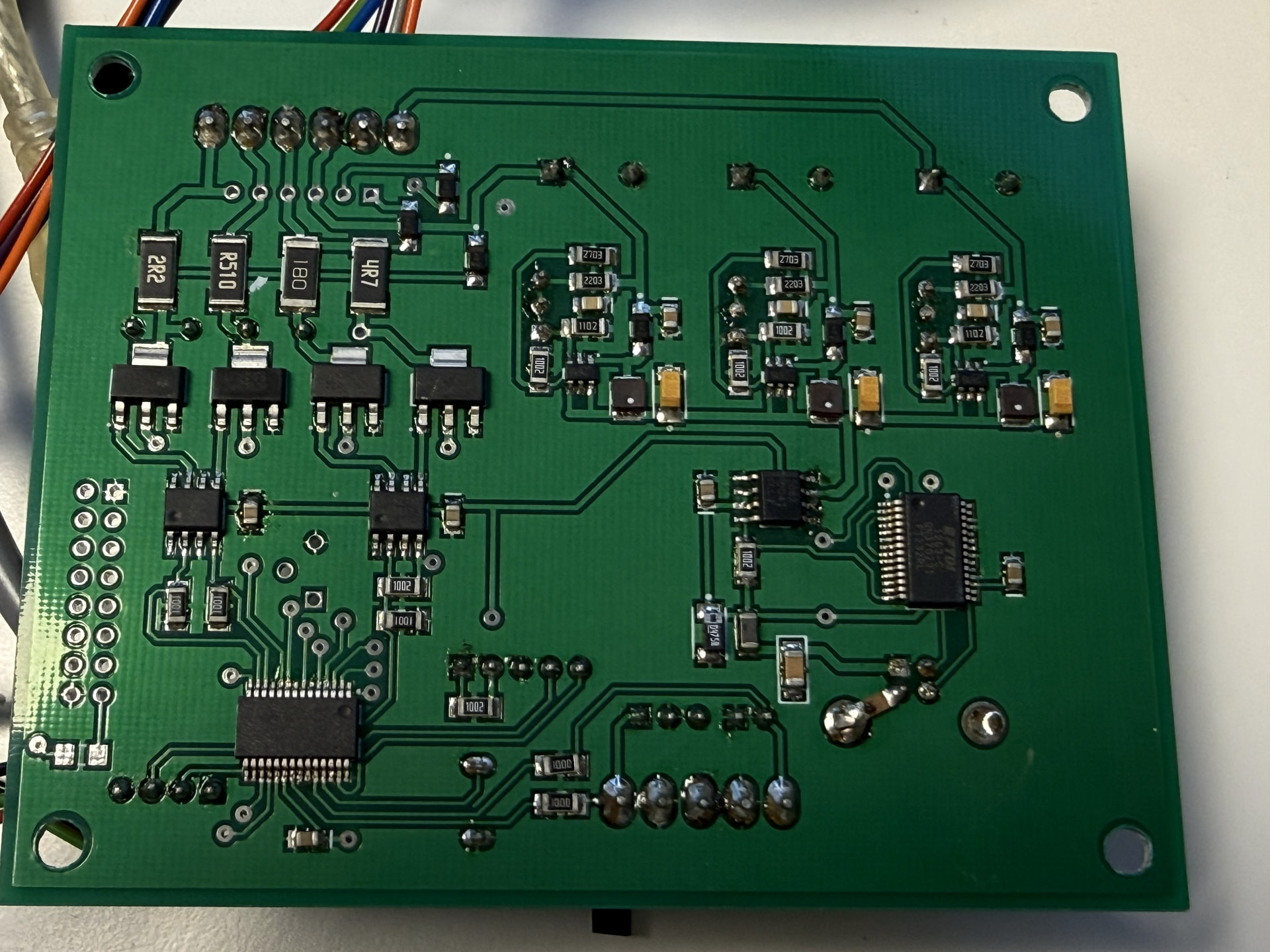
Originally, the LED system and the camera were triggered by a Hall sensor. There’s a manual for performing a laser compatibility upgrade on the existing board, but to prevent potential system damage, I decided to connect the incoming trigger signal to the fiber optic detector using an optocoupler or a control signal from the Teensy. Since the HS-CFLed board will control the LEDs and the camera trigger, I’ll be controlling the motor and possibly the input trigger of the fiber optic detector from the Teensy. In preparation, I’ve already taken a look at the Arduino/Teensy code posted here. Regarding triggering the system based on sprocket hole detection, I do have a question: For film formats up to and including 16mm, a trigger for each pulse from the fiber optic detector seems logical to me, given that each frame has one sprocket hole (the location doesn’t matter). For larger film formats, such as 35mm, multiple sprocket holes are present per frame. Is it true that the posted code doesn’t include a counter for the number of sprocket holes that must be passed before a trigger occurs? The film format selection and thus the number of sprocket holes to be passed for each trigger. Or did I misread the code? @Andriy_But: The HS-CFLed board can achieve what you’re trying to achieve: three exposure captures. I’m not sufficiently electronically skilled to backward engineer the board myself. Below are some photos of the board. They might be of interest to someone with an electronics background, or simply for inspiration.
My system also uses two optocouplers driven by the Teensy for the camera and the light.
It works without any issues and it’s safer. This choice also allows me to use LEDs with different voltages for my tests without having to modify the scanner’s hardware (since I use a regulated power supply dedicated solely to the lighting).
My laser has an internal function that lets me set the number X (1 to ~10) of perforations detected before the signal is sent to the Teensy. I don’t know whether this feature exists on other lasers; I actually stumbled upon it by chance while browsing through the device’s menu. And since I’m a bit lazy sometimes, I saw it as an opportunity not to have to write any code. But if needed, it shouldn’t be too difficult to code.
The counter in the app only counts the signals sent by the laser and does not determine when the camera is triggered.
The laser signal reception and the camera trigger are handled exclusively by the Teensy, and therefore by the Arduino code. The PC application doesn’t manage this. It’s more direct—I was worried that synchronization issues might arise if it went through the PC.