No, I don’t think so—after all, you found a Basler component that’s a real plus.
I was also wondering why you didn’t choose a coaxial pinpoint laser. Is there a technical reason?
No, I don’t think so—after all, you found a Basler component that’s a real plus.
I was also wondering why you didn’t choose a coaxial pinpoint laser. Is there a technical reason?
Honestly I have no idea ![]()
Year ago I’ve read some thread here about lasers and it was a mention of Keyence assembly of this sort in someone’s machine design. That’s how I found used assembly on eBay. Probably not the best solution, but I’m new to engineering world and it’s just trial and error. Fortunately it does it’s job pretty well.
The main thing is that it works ![]() , Don’t pay too much attention to my comments below. Test your system first.
, Don’t pay too much attention to my comments below. Test your system first.
For your information only, there are 3 mm coaxial fiber optics that emit red light and detect the reflection of that light (for example: https://www.baumer.com/ch/fr/apercu-des-produits/detection-dobjets/capteurs-a-fibre-optique/gamme-de-capteurs-a-fibre-optique/differentes-variantes-des-fibres-optiques-cylindriques/fce-050c1y10/p/26569).
You still need to add a lens that will focus this beam to 0.1 mm (https://www.baumer.com/ch/fr/p/34429).
The advantage is that you can get very close to the camera and detect the perforation used by the camera’s claw, to be more precise in positioning the film.
You also have more place for the light block, since you don’t need a reflection mirror.
Another remark: the farther you place the laser from the camera, the more likely splices are to trigger false frames. In other words, your laser will glitch on the splice and trigger one extra frame, while at the same moment your camera is capturing a clean frame. You’ll end up with a misaligned frame, and a few frames later the splice will pass in front of the camera. Depending on how many splices there are, fixing this in post-production can be very tedious.
Well, this coaxial laser looks great, maybe I’ll update this fixture later on. In terms of benefits, the light block size definitely struggles from having the mirror underneath, but it fits nearly perfect. In terms of a claw, the laser head can be positioned to register 3 sprockets from a gate. It looks big, but the actual laser window is close to the top of the assembly, so I can position it this way.
I’ll test it with different films, gauges and speeds firstly to see if there would be any improvements from alternative fixture, but thanks for sharing anyways.
Today I’ve made a first run of a scanner on one of the films to compare with my old setup (frame by frame projector to Sony A7RII) and can verify that stability of new machine is surprisingly better, but the resolution and sharpness is not. Looking for new camera/lens combination to incorporate.
Also I’m exploring different LEDs and consider designing RGBW fixture of my own to have best color accuracy possible.
The holiday season is approaching and people are certainly busy with other things, but I find this forum pretty quiet.
Here is finally a video I made about how my machine works:
Happy holidays to all of you, maybe a bit in advance… ![]()
Looks amazing! ![]() You use AviSynth for the post processing, am I correct?
You use AviSynth for the post processing, am I correct?
I only use Avisynth for DustRemover and, more recently, for automatic color correction. Avisynth is complicated to set up and rather slow, even in the x64 version. I prefer to create several versions of the same clip with Neat, Topaz, and DaVinci Resolve, and then mix these versions together in the end, adjusting the transparency of each one to my liking.
First of all, thank you for livening up the forum, which had certainly been rather dull lately.
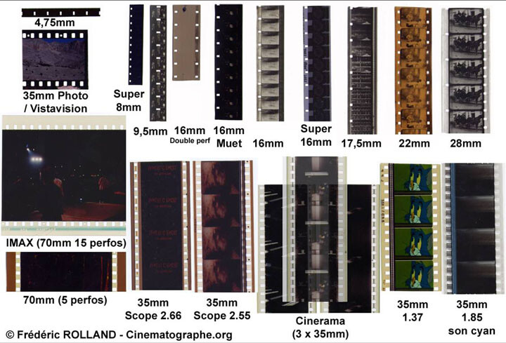
I was surprised by the excellent quality of the digitized images, especially the fragment corresponding to the 4.75 mm format. I must say that I was personally unaware of the existence of this format. I thought the smallest format was 8 mm. However, even in the small 4.75 mm format, the images appear absolutely sharp with natural, saturated, and high-quality colors.
My sincerest congratulations on the excellent work done in the design and construction of your scanner and the outstanding results achieved.
Thanks for your message Manuel_Angel.
The objective is to show that a single machine can handle all formats—it works!
There’s no need to include capstans or tensioners. Film tension stays very low, since the driven reel is free-running. All you need is a direct drive with a stepper motor, with speed control.
A setup where switching from one format to another doesn’t require lots of adjustments. Only 35 mm films require removing an element from the lens.
After that, everyone builds their machine according to their preferences, their budget, and the formats they think they’ll need to digitize (as for me, at the beginning I only had Super 8 to digitize… that didn’t exactly go to plan).
PS: I’m still missing some 22 mm and 28 mm films to complete my collection. These films are very rare and therefore very valuable. If you have any, I’d love to try digitizing them, taking all the necessary precautions. The only limitation is that they must still be in good physical condition, because my setup can’t digitize heavily damaged film.
Congratulations @Roland the video is a great showcase of an already excellent project and design.
And yes, the forum has been very quiet indeed, so it was great to see your great post.
Spellbinding look into an era long gone.
Love your design, it both looks sturdy and “simpler” than some of the other designs, without making compromises from what you explain. I’ll spend some of the holiday continuing my Gugusse build, but always considered yours, so maybe that’s a future project ![]()
The Pathe scans (both formats) show black scratches. I’m not an expert, but if they are not on the image-layer-side of the film, then a “wet gate” may help in removing those, if you wish to investigate that.
Congratulations on your design and build.
Hi @Roland,
I’ve never seen any 22mm or 28mm films you mentioned, nor was I even aware of their existence.
I’ve only digitized my own films and those of some friends, but all of them were in Super 8mm format.
Best regards
I had to look up 22mm. I’ve never heard of it. We’ve scanned a fair bit of 17.5mm and 28mm on our ScanStation. 17.5 is similar to 16mm, 28mm is close to 35mm. Both are pretty rare.
Exploring the history of cinema through film formats is fascinating.
Regarding 17.5 mm: despite fairly widespread use in France, this film format came to an abrupt halt in 1942 following its ban by the German occupying authorities, who also required that all registered equipment be converted to 16 mm, the propaganda format used by Germany at the time (source: Wikipedia).
As for 22 mm, there are two versions.
The first is a version with double perforations in the center and three images side by side, manufactured by Edison at the beginning of the 20th century, I believe. Impossible to find.
The second version is rare and was developed by the Gallus factories in France between 1921 and 1926 (I had to use ChatGPT for this information). For this second 22 mm format, I don’t think it’s impossible to find some. I have already digitized film reels in 35 mm or 17.5 mm formats from that same period.
Do you think it would be possible to find and digitize 4.75mm film ? And yet. ![]()
Many thanks for all your excellent work. I’m waiting when you have prepared all your plans to build the scanner.
Still on the topic of this multi-format scanner… which now includes a stop-motion function, for example to increase the exposure time with very dark film.
This also makes it possible to see whether the scanner could support mounting a frame-by-frame camera, such as a Raspberry Pi (which many people use).
Incidentally, the question is whether you really need a scanner equipped with tensioners, a capstan, and other complications to accurately position each film frame.
In your design, the gate (and maybe by the cleaner clamp) set the tension. Direct driving the film from the pickup-up reel has the effect that as the film is coiled, the reel size increases (the radius increases), and the film-step also increases with the radius. But that is a workable problem.
Because of the variable radius, an accurate hardware sensor is required (which you have with the movable laser).
As long as the film is good enough to fit in your gate design, I think it should work.
“Required” is a little strong. I don’t have a hardware sensor for that part unless you count the camera sensor itself. My software is doing it optically with an algorithm that adapts to the changing radius as it goes along.
The theoretical minimum film transport doesn’t need much more than a way to drive the reel and a way to sense tension so you don’t tear the film.
Actually, if I understand Roland’s point on his post correctly is that tension sensing is not required. If I am not mistaken (@Roland please confirm) the current design does not have any tension sensing. His point -I believe- is that tension can be set mechanically (in his case by the gate friction and the detent torque of the supply stepper).
Thanks Nick.
I was thinking of the accurate hardware sensor as any hardware means (including the camera). Note that -on my scanner- the only sprocket position sensor is extracting the position from the captured camera live stream (on a Rpi4 + HQ which is rolling shutter at only 10 fps). If using global shutter + higher framerate + more processing power (Roland’s scanner configuration), sprocket position may also be performed similarly without a laser sensor.
But I concede your point, perhaps a better way to phrase is that in Roland’s design, the pick-up motor control would require feedback for the stop location and/or compensate for the changing spool radius. The feedback would need to be as accurate as the stopping requirement.
And yes, there may be mechanical ways to stop the film at the desired location and disengage the pickup-motor.
Again, thanks for the feedback Nick.
I’m going to try a few replies.
The cleaning clamp doesn’t play a major role and was not used on the 16 mm film.
You’d be surprised by how tolerant this system is when it comes to handling twisted or warped film.
I do use a laser system that is indeed precise (beam diameter 0.1 mm), because for me it was the simplest system to implement. Even if a perforation isn’t always representative of the exact position of a frame.
The film is held passively by the film gate and by the left stepper motor, which is never powered during “stop-motion” operation.
I’d like to remind you that this “passive” tension is low and cannot, under any circumstances, cause the film to tear (over 150 km of various films have been tested).
So there’s absolutely no need to worry about that.
If I understood your message correctly: I don’t need any feedback to compensate for variations in the reel radius. Only the laser controls the stop command for the drive motor. Once the perforation is detected, the motor remains powered to lock the film in place. Simplicity shouldn’t be intimidating ![]() . No feedback from the drive motor is needed. Everything depends on the laser’s accuracy and the system’s responsiveness. Maybe the video will explain it better than my awkward explanations in Shakespeare’s language.
. No feedback from the drive motor is needed. Everything depends on the laser’s accuracy and the system’s responsiveness. Maybe the video will explain it better than my awkward explanations in Shakespeare’s language.
Ah, I almost forgot—happy holidays, everyone!