My Home Made Telecine I wanted to share with you

Hi !

Today, as I was working with my girlfriend on a little musical video for her, I decided to share with you my machine I’ve build during the lockdown last spring. I wanted to share something because I’ve spent hours and hours reading the Kinograph forum, trying to understand what people are saying (I’m a photographer and a musician and knew nothing about electronics, programming and arduino…I’ve even learn to solder this spring…as we say in France, I have two left hands).

So here is my telecine, that my 11years son call “The scanner of the Super 8”.

Telecine

I’m using and Arduino to controle the Nema17 stepper on the take up spool, to analyse the light sensor for the sproket holes and to send the signal to a Raspberry Pi that take the photo. The cam is the Rasp HQ Cam, and I take Raw/DNG files 4056x3040 px.

Then I import in Lightroom, export in Jpegs, and Stabilize with Blender using the sprocket hole tracking.

The sensor is a 2€ light sensor I plug in the analog input of the arduino so I can programme a threshold for negs or inversibles. For the moment it’s perfect with dark side but when it’s transparent, it’s not easy, it depends. I received a reflective IR module last week I have to have a look.

The supply spool is mounted on a really small and cheap 12V DC motor I received with my arduino, that turn in counter sens, the tension is just enough for the film to stay steady but with to little torque to be aggressives.

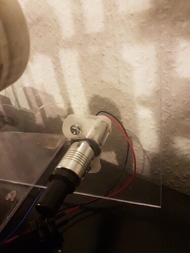
The led is a 6€ led and the lens a reverse 50mm Rodenstock Rodagon (from my enlarger I don’t use since 3 years). Everything is made with plexiglass, cardboard, scotch tape and a MakerBeam Starter kit.

The rolls are Skateboard wheels.

And…well… it’s very slow but it works. 3h for a 15m reel, but as I use it for my own films I shoot and developpe myself, I never have 100 films to scan so it’s ok for me. I use it for film and to take still images for my photographic work… I could go faster I think but… sometime I’m lazy you know…

So… Thank you to all the members of this wonderfull forum for helping me in this adventure, it was so passionating that I almost forgott I lost all my job as a musician because of the lockdown :slight_smile:

2 extracts of what I’m doing this week with it, 1 roll of Trix developped in my bathroom, shooted in the holy B-Mode from my Nizo cam, for are musical video. The quality is poor on youtube and from my images as those a tests with exports from Lightroom at 540 px (old CPU so I make light tries).

B-Mode / my friends

And 1mn of our first tentative to sync S8 and music… And…it works. (and yes I discovered rotoscoping too :slight_smile:)

Sync and shameless rotoscoping

And last image, a still image, a color one from my work in S8 and my chemical incapabilities (that I assume and like):

I wanted to share this as this site as a responsability in the huors I’ve spent learning and trying. I hope my english was understandable !

Cheers from France,

Gregory
7 Likes

** Gregory_Dargent**

Bravo !

1 Like

Merci dan74, ça a été bien du travail pour un debutant comme moi !

Thank you dan74, that was a lot of work for me, being totally noob…

I am very much interested in your use of Raspberry Pi HQ camera. How did you manage to get RAW stills out of the camera? Did you use the Picamera app? Eager to see some photographs of your system. Thanks.

3 Likes

Hi Udayarangi,

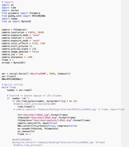
Yes I used Picamera library + pydng.core (RPICAM2DNG), with a “paste and copy” made code and help for programming from the very nice Denis- Carl Robidoux for the automatic file transfer (Creator of the Gugusse Roller).

Some images of my telecine :slight_smile: Not really beautiful but that the maximum I can do for the moment, and I’m waiting for laser to detect holes for color negs and b/w neg (and expired films I’ll process).

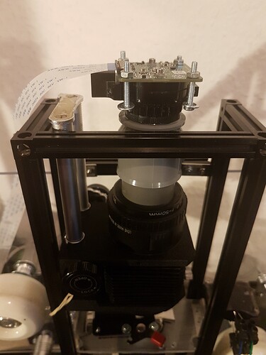
HQ Cam + Extension tube made of plumbing pipe + lens. The gate is from a Heurtier projector sold for parts 10 euros…

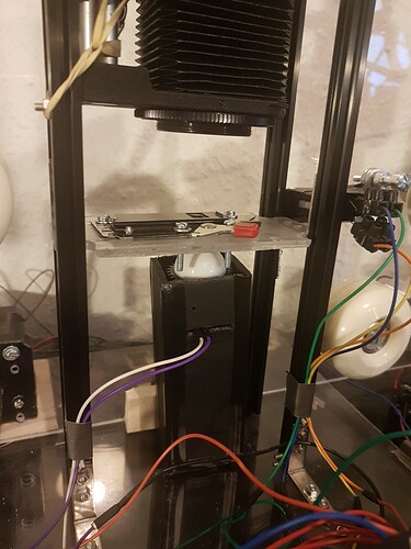
LED + sphere from one of my lightmeters

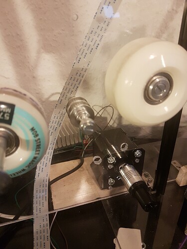
NEMA 17 motor directly on the take up spool

Little DC Motor on the supply spool, turning in the counter direction, so the film is in tension, but with really weak torque, so there is no risque of damaging the film.

And a still with my system…

I wanted to make one that will cost me less than 10 lab numerisation (250/300 euros for 10)… and I managed to do it so, now, some monthes later, I can say I’ve earned money with this as I scanned my 11th film roll :slight_smile:

Cheers

Gregory

4 Likes

Thanks. It is interesting to know a very simple/ effective approach. I could use your idea to use a stepper motor directly to the take up spool using Arduino. In my present test set up I was using a Geneva Drive taken from an old 35mm projector to advance the film (35mm). I was looking for a sprocket less method to run old films. Could you explain the sprocket detecting method you used.
Thanks again.

Yes I tried to make the simpliest possible because of my own (in)capabilities in electronics, programming and diy…

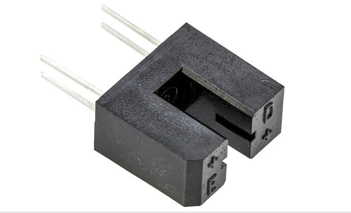
I just used this kind of 1€ sensor (I don’t know it’s name in english, in french it’s called “fourche optique”):

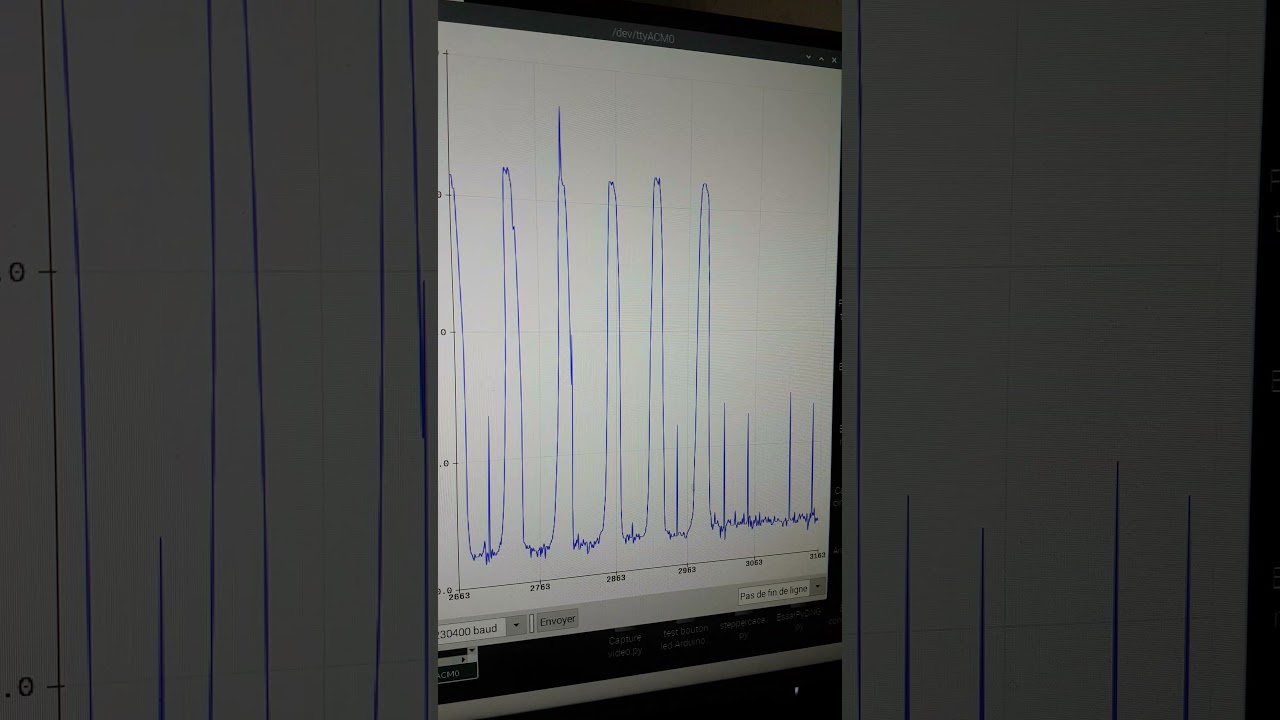
I plugged it’s sensor output in the A0 analog input of my arduino, and do a serial plotter to find the threshold between the hole and the film… Then I adjust in my code (it take 1mn in all)… The stepper moves the film, when the sensor detect the hole, the motor stop, the arduino send a signal to my Rasp PI via USB and the HQ cam shot. Then after 2s the motor goes on again (under 2s I’ve found some bluried images, I think the camera or the saving of the images are slow so with 3400 images, sometimes it’s too quick…I wish it could be faster but I have no idea… perhaps to link the Rasp Pi and Arduino via GPIO is better and faster than via USB. If someone knows I would be happy to know :slight_smile: ), make some steps (40) ignoring the sensor (because there will be 1mm hole that the sensor still read) and then again in the loop.

It works perfectly with B&W positives as the side is totally black and the sensor has no problem to discern hole and the film . With negatives (with clear side), it depends of the quality of my processing, but when everything is regular, it works great. That’s why I’m waiting for a laser to try the reflective method as I’m processing everything by hand and with some very expired films :slight_smile:

Cheers

1 Like

Great work! Can I ask, why did you use multiple rollers, and not just 2? It seems like a long path, but I don’t understand the reason. I think the skateboard wheels are very clever!
Thank you

Thank you Junker…

I’ve used 4 rollers because… I bought a 4 pack wheels and it was fun too make them turn… and I thought it would give more stability with the film tension, to make the film move the less possible during the capture, but I’m really not sure that it is a physical reality, only in my mind :slight_smile:

And the idea of the Skateboard Wheels was taken from Gugusse Roller start [Gugusse Roller / Gugusse Compact]

Perfect explanation!

1 Like

Gregory,
I watched the video of Gugusse Roller. I noticed that the film is moving (slowly) when he is taking the capture. But in your system the frame is still during capture. To me your captures look sharper although they are 8mm frames. The 35mm captures from the Gugusse Roller looks soft to me.

Udayarangi,

The Gugusse Roller seems to be a nice system with a different conception. But yes, perhpas is it softer mostly because the camera is placed by hand in front of the film, on a stand, and that is by far less precise for focusing I suppose than a macro rail or a bellow like in mine. The other thing is that I process fresh films, mostly black and white, with a lot of contrast, that helps a lot for focusing on the grain… My color scans are softer too and harder to focus.

And my system is really slower, so yes the image stopes in front of the lens but the scan is 3 or 4h long for a 15m reel…so precise… and slow…

Gregory,

Wonderful!
I build a more crude system in 2017 which worked well until DSL camera failed. I have been studying Raspberry/Arduino solutions ever since, but have not made any decisions. Your system helps me have hope! I have many old projectors for parts.
My System

Stabilized results (from 1977 film?)

Thank you for sharing!

Jim

2 Likes

Hi ! Nice systeme and nice result (1977… when I’m born :slight_smile: ). For me it was a good solution with Rasp Pi and Arduino, but there are many solutions I think… The most difficult thing for me is definitively the sensor to detect those small holes… the other thing where really just new things to learn, with a great pleasure pleasure…

1 Like

Congrats on a great build with many clever solutions. I’m so glad others are finding it useful. Thank you for sharing your build and your experience here so we can all benefit :slight_smile:

And congrats to your girlfriend on the beautiful song!

Yes, I have seen some later transfers. And they are pretty good. He states he has got rid of the wobbling.

@Gregory_Dargent, I am building a similar scanner. I have tried a few methods for sensing the perforations on the film edge with uncertain success. Laser sensors encased have been my best option so far with highest success rate but it’s far from perfect. You had mentioned on the forum that you " programmed the threshold " of the opto-switch in Arduino IDE. Could you please share your Arduino Sketch or just the part related to controlling the threshold of the opto-swith?

Hi @OverCranked !

So to explain my setup:

My Sprocket Reading cell is plugged in a Analog Input (A0). Not Digital Input, as I need something else than 0 and 1.

When I scan a new film, I run first this small program that just run the Super8 reel slowly and print the reading of the cell (reading the laser through the side of the film) on the Serial Plotter from the Arduino IDE.

Then it give me a value telling me the difference between when there is the side of the film and when there is the sprocket hole. I keep this value (so, it not SOOO precise, in the example from the video you see that there is a big difference between hole and film as it’s a b&w positive… with negatives the difference is really smaller. ), and use it in my programm to tell the arduino: when the reading reach this value, you stop, you shoot and wait 2s and then you go back to work :slight_smile:

an explanation, sorry for my early morning frenchman english :slight_smile:

The program for the reading:

// Define connections
#define LED 2
#define DIR 8
#define STEP 9

const int analOpto = A0;
int optoRead = analogRead(A0);

boolean setdir = LOW;

void setup() {

Serial.begin(230400);

pinMode(DIR, OUTPUT);
pinMode(STEP, OUTPUT);

pinMode(LED, OUTPUT);

}
void loop()
{

{
delay (20);
for(int x = 0; x < 1; x++) {
digitalWrite(STEP,HIGH);
delayMicroseconds(30);
digitalWrite(STEP,LOW);
delayMicroseconds(300);}

optoRead = analogRead(A0);
Serial.println(optoRead);
delayMicroseconds(500);

}}

Cheers

Gregory

1 Like

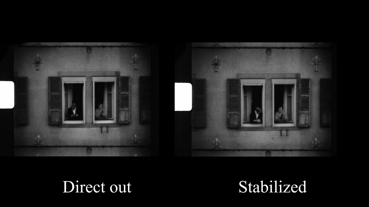
the difference between direct out and stabilized with free version of Da Vinci resolve

3 Likes