Although the picamera2 library is still under development in alpha version, it seems to be in fairly widespread use.
For this reason I have decided to adapt my DSuper8 capture software to the new library.
During the last few weeks I have carried out quite a few tests and, in general, the behavior of the library is correct. Only on a couple of occasions have I observed the blocking of some internal function of the library.
Camera management with the picamera2 library is very different from the old picamera library, however, from the user’s point of view, the use of the software is very similar to previous versions.
I want to thank @cpixip for his contribution to the archive imx477_scientific.json which, in my opinion, provides very good quality images.
Thanks @Manuel_Angel Manuel for all the efforts done and the great support provided. My Bauer T192 scanner with new DS8 software runs smoothly, very stable and with great results.
im currently testing your software, it looks great so far. some points:
i added a requirements.txt for easier install of dependencies ( pip install -r requirements.txt)
# Automatically generated by https://github.com/damnever/pigar.
exif==1.6.0
matplotlib==3.6.3
numpy==1.23.5
opencv-python-headless==4.7.0.72
PyQt6==6.5.1
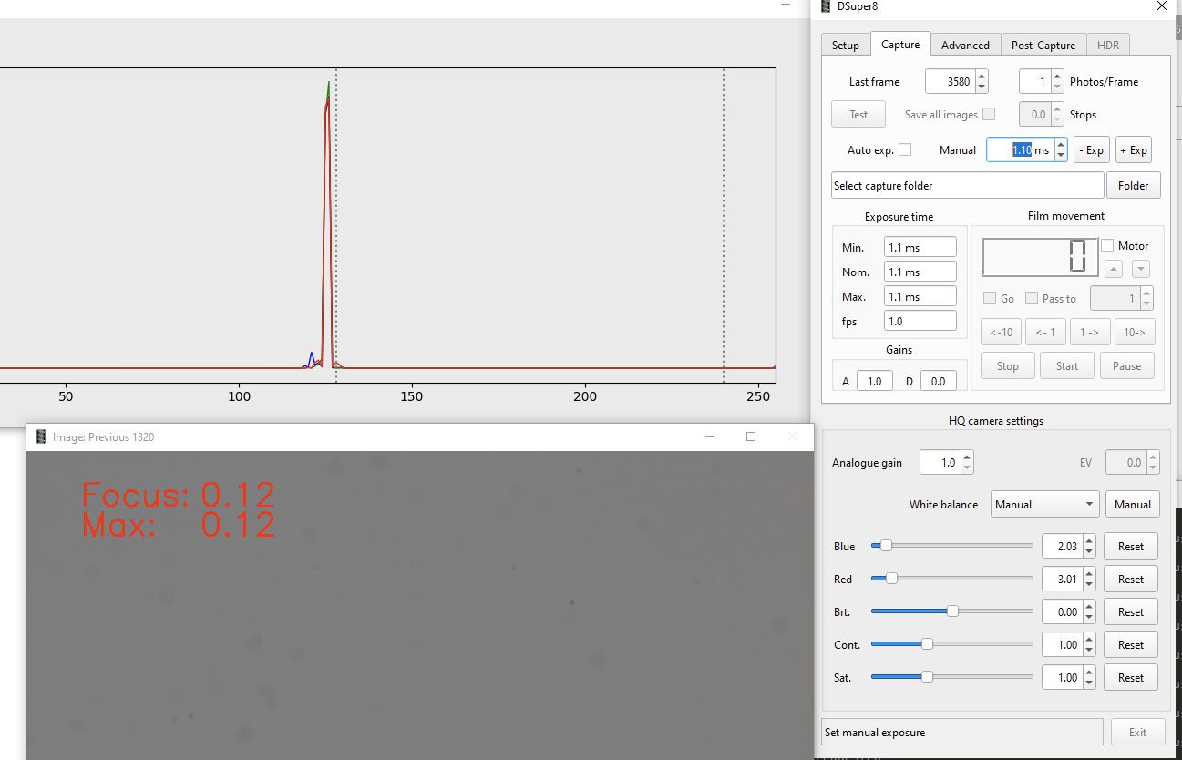
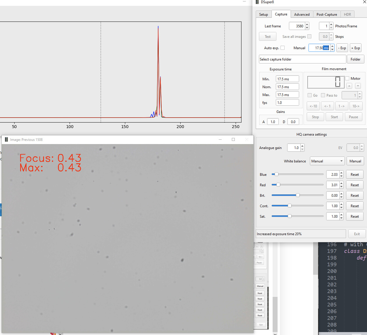
I wanted to start from the very beginning: Calibrate light ( exposure time and white balance) with selecting only the empty filmgate with a higher zoom so no black border is visible; theni added two indicators to the histogram:
        # Add a vertical dotted line at x=128
        plt.axvline(x=128, color='gray', linestyle=':')
        # Add a vertical dotted line at x=128
        plt.axvline(x=240, color='gray', linestyle=':')

        self.fig.canvas.draw_idle(
I can’t get it to 128 exactly without touching Analogue gain, so leave it there.
Now i try to check for a equal illumination distribution over the filmgate so i do this by setting aperture to 16 on the componon S and with longer exposure time i get this image of a dirty lens i guess but no vignette so that ok i guess:
then set aperture back to ~4 and increased exposure time until most of the spikes were around 240 and got my minimal exposure time for a image with all highlights.
I have always found it very exciting to see my software running on other users’ computers.
I think it’s very good that you adapt the software to your tastes and needs. It is exactly what I did in his day.
In order to include it in the software distribution, I would like to know more details about how you have generated the requeriments.txt file and if the dependencies have actually been installed correctly.
Following the suggestions of @d_fens I have updated the user manual including instructions to automate the installation of client software dependencies using the pigar tool.
Recently I have been studying @Moevi.nl 's suggestion regarding the possibility of executing the DSuper8 software in its entirety, that is, both the server program and the client program simultaneously in the same RPI4 machine.
Made the appropriate test, I have to affirm that, in effect, it is a valid option. The software is executed fluently and without problems.
Logically, the benefits in terms of capture times are lower with respect to the use of a PC as a client, but if we are not too demanding, the system as a whole is perfectly usable.
The HDR fusion algorithm is really responsible for the greatest slowness. While in a PC the 6 images HDR fusion is carried out in a second fraction, in the RPI it takes approximate time of 5 s.
The capture of an HDR frame with 6 images with PC takes a time of about 2.6 s. With the RPI we are going to the 8 s.
On the other hand, the DSuper8 client software uses Python 3.10 and PyQt6, while in the repository of the Bullseye operating system we find Python 3.9.2. and PyQt5.
That is, in other words, we have to compile and install the required versions of Python and PyQt6 in the RPI.
Hi @Manuel_Angel I saw the nice video posted by @Moevi.nl of his work, which uses your software.
I am new to python and do not read it well :). From what I understand from your code, it uses pigpio to define a waveform and then the library send this waveform to generate the pulses.
I have a suggestion to improve your control of the stepper, and the movement of the frame. In looking at the posted video, the start and stop of the stepper creates a bit of shaking. Using arduino and pico, I implemented a linear start and stop that makes the stepper run very smoothly.
The theory of how the stepper works is described in this Atmel paper, maybe the paper is a bit dense.
When I implemented the stepper control with a projector gate, with a claw, I also stopped mid turn -when the claw is fully engaged- and use that position to move the pickup reel, before moving the second half of the turn to complete the frame positioning. I also recall reading something in your code that there is a mode where you back one frame, before moving forward, which would create additional shaking.
In simple terms, instead of a single period for all the pulses (a single frequency), the process creates progressively from longer to shorter periods at the start, and progressively from shorter to longer periods at the stop. The other advantage is that it would allow the stepper to run slightly faster providing the torque and power allow it.
I think that can be achieved by replacing the single pulse period to create the wave, by a combination of a start pulses, mid pulses, and a stop pulses.
Without going into the complexity of the Atmel paper, you can implement a quick test to see the effects of a slow start/stop with something:
# start_pulses
for i in (50,2,-1):
    # pin ON
    pul_start.append(pigpio.pulse(1 << pulsePin, 0, int(float(tus)*float(i)/2.0)))

    # pin OFF
    pul_start.append(pigpio.pulse(0, 1 << pulsePin, int(float(tus)*float(i)/2.0)))

# mid_pulse sequence (same as you have it)
# pin ON
pul_mid.append(pigpio.pulse(1 << pulsePin, 0, tus))

# pin OFF
pul_mid.append(pigpio.pulse(0, 1 << pulsePin, tus))

# stop_pulses
for i in (2,50,1):
    # pin ON
    pul_stop.append(pigpio.pulse(1 << pulsePin, 0, int(float(tus)*float(i)/2.0)))

    # pin OFF
    pul_stop.append(pigpio.pulse(0, 1 << pulsePin, int(float(tus)*float(i)/2.0)))
And then correspondingly incorporate start_pulses, then 3102 mid_pulses, and then stop_pulses, into the wave.
The above is not linear acceleration, because the coefficients are only simple progression.
If you like the results, you can then implement the formulas for the coefficients for the start/stop pulses and increase the number of pulses on the start/stop which would allow a reduced mid period.
Let me know what you think, and I can also share the simple implementation to calculate the coefficients that I did on the PICO.
My understanding of the pigpio is limited to reading your code, so my apologies if I missed something on how to implement the variable period pulses in the start and stop.
Update: corrections to the loops and typecasting for the multiplication to be float. Sorry if my reading of python is limited, my writing is worst!
I am currently using an Arduino Nano to handle my steppers, utilizing timer-interrupt routines.
[For the curious: One dedicated timer handles the film advance, the other timer the two tension control steppers.The tension steppers (simple 28BYJ-48) are controlled by two separate PID-controls (where I=D=0 currently), and are called periodically by TIMER2 - that is the simple part. The film advance routine (this is a “real” stepper driven by a TCM2208) is more complicated, using a table of delay times like this here:
together with a velocity variable which gets incremented or decremeted, choosing a different delay for the next time step. In this way, a suitable acceleration or deacceleration ramp is realized.]
My current code is quite old and I am considering moving from the Arduino to the Pico with Micropython. Do you or anybody else have any experience how precise the timing is with a Pico and pure Micropython? Of course, there is always to possibility to utilize the PIO-hardware on the Pico to get a better timing than with pure Micropython… - any experience available at the forum?
No experience with Micropython, all work has been with C++.
I found this 15 min video very helpful in getting the toolchain setup in Windows for the Pico, and up to speed. It is my understanding that one can also use the Arduino IDE, but I chose not to.
The Pico clock default is 125 MHz, so there is a lot more clock cycles to work with. Also I have not yet used the Pico second core, but at some point, it may be an interesting alternative.
Initially I looked at some arduino implementations of the Atmel paper, this video documents it well, and it also uses interrupts to coordinate multiple motors.
Like in the video, and your explanation, I initially worked with an array for the timing in the Arduino (in my case the Uno). I did not make the implementation with interrupts, in either the Uno or the Pico.
Basically I divide the number of pulses commanded in 4. The first quarter is acceleration, the fourth quarter is deceleration. Quarters 2 and 3 run at a constant speed.
For the Pico, the coefficients are calculated on the spot, using the Taylor approximation in the paper.
One trick that I came up with is that if one stores the first and last coefficient on the acceleration portion, then the deceleration can be calculated from these. The limitation is obviously that the ramps will have the same slope.
The code below is a stepper portion of the work in progress in the PICO for the SnailScan. Each Stepper is an object, and can be set at a different microstep and -if geared- gear ratio.
Here is part of the class that explains a bit the settings used for calculating stepper_alpha and C0.
class ss_TMC2208 {
  public:
    uint ss_tmc_en;   //io pin corresponding to Enable
    uint ss_tmc_ms1;  //io pin corresponding to ms1
    uint ss_tmc_ms2;  //io pin corresponding to ms2
    uint ss_tmc_step; //io pin corresponding to step
    uint ss_tmc_dir;  //io pin corresponding to dir
    // MS2, MS1: 00: 1/8 | 01: 1/2 | 10: 1/4 | 11: 1/16
    uint ss_tmc_ms21_set;  //Current setting for MS2 and MS1
    const uint ss_tmc_ms21_steps [4] { 1600, 400, 800, 3200 };  // Number of microstep, per turn, corresponding to MS setting.
    const double ss_tmc_max_acc [4] {10.0, 2.5 , 5.0 , 20.0}; // Maximum acceleration setting, corresponding to MS setting.
    const uint ss_tmc_step_min [4] { 160, 640, 320, 80 };       // Minimum time in uSeconds for normal steps (non-accelerated) for each MS setting.
    uint ss_tmc_step_set; // Minimum time in uSeconds for normal steps (non-accelerated) for current MS setting.
    const double ss_tmc_inv_tt = 14000.0;
    const double ss_tmc_gear_ratio = (double) (13.0 + (212.0/289.0));  // Default Gear Ratio //
Note I am not doing any compensation for the calculation times. Which is basically and added constant for every coefficient (except C0 and C1 which are precalculated). That can be an area of improvement, but it has not been an issue.
A quick explanation of the calculation terms. ss_tem_ms21_set is an index (0 to 3) to the items in the arrays ss_tmc_21_steps, ss_tmc_max_acc, ss_tmc_step_min. This index allows the above method to work for different micro stepping settings, while providing the ability to tune each setting, to the stepper minimum pulse period and acceleration capabilities. I implemented these in order to perform testing on the pattern with different micro stepping settings, but the above can be simplified by replacing the ss_tmc_ms21_steps[ss_tmc_ms21_set] for Acceleration setting (ω in the Atmel paper).
Update: Also the term ss_tmc_ms21_steps[ss_tmc_ms21_set] * ss_tmc_gear_ratio can be replaced by the number of micro steps for the stepper to make one complete turn.
Thanks for the Atmel document and your suggestion. All possible improvements are welcome, especially when it comes to software that only requires thinking and writing code.
I am not a professional programmer. My knowledge of Python is self-taught.
When a modified projector is used to transport film, to advance one frame only the main axis of the projector needs to be rotated exactly one turn. I have always started from this principle and have never used sensors to detect the correct positioning of the frame. The projector mechanism itself already places the painting at the exact point.
To rotate the shaft one turn and then wait until the next turn, a stepper motor is logically ideal.
I have seen implementations of accelerations and decelerations in stepper motors that are used, for example, in 3D printers, but in the case at hand, given their simplicity, it had never occurred to me to use them.
In my case, to reduce vibrations I use the maximum resolution given by the motor controller 32 microsteps per step, 6400 microsteps per revolution and I include a small delay before capturing the image. On my device, in my opinion the operation is quite smooth.
The mechanics of the projector itself also have their importance.
I am aware that there are some users who also use my software and in no case have I been informed of problems with vibrations.
Indeed, in my software, with the pigpio library, a wave is built that is sent to the motor controller and makes it move forward/backward one frame. All wave impulses are equal.
I’m going to study the Atmel document and your proposal and try to test it on my device. It would try to create an acceleration wave, another constant speed wave and another deceleration wave until the motor stops.
In my software, once you have positioned a film in a known position, for example the first frame of a film, it keeps track of the physical position of the film. It is perfectly possible to exactly advance or rewind an arbitrary number of frames.
On the other hand, the film drive holes are always somewhat larger than the projector drive teeth, so that if the film is retracted there is a small positioning error due to the existing hole-tooth play. In small formats, such as Super8, this error is very evident.
I thought that the simplest and most accurate way to eliminate the error is for the last movement to always be forward. For example, if I want to go back 10 frames, I actually go back 11 and go forward 1. In my captures I have never observed any problem related to this behavior, although logically the more starts and stops, the more vibrations will occur.
I have yet to complete my self teaching so your knowledge of python, QT, and picamera2 far exceed mine… but I am learning.
I too started without micro stepping, and without acceleration. Found the improvement in micro stepping amazing, but not the speed. The speed and performance of the stepper with acceleration is well worth the trouble to implement it, and in general, will also make the stepper significantly less noisy.
Let me know if you need anything else, happy to assist.
@PM490 Pablo, thanks for the write-up above! The two videos you linked to were very interesting for me. My implementation is actually also based on the Atmel paper; the list of delay were however pre-calculated with the exact formula of the paper. As a funny side note: I also splitted the total movement in four segments, with the first and last segment doing acceleration/deacceleration and a middle section with full speed.
The first video reminded me actually of old days were I was doing C/C++ programming via comandline compilation - there were always some libs or flags missing or misspelled in the Makefile. So… - I think I will stick to programming the Pico with Micropython using the Thonny IDE. I will do some timing tests with the Pico and an oscilloscope to find out. If a Pico/Micropython setup works with my scanner, I will report here.
Just for the aspect of having s personal coding mentor: I can only recommend ChatGPT as a high level coding assistant, asking for code that implements this and that is a real productivity boost especially in the pro version where you can use plugins that analyse a GitHub repository and gives code using it or just recommends libraries for a given task and so on. Still needs proofreading as hallucinations do occur but overall it’s a great tool for learning and getting initial hints.
I got the software running like a charm.
My steppenmotor and led work too.
I would like to use a hdmi camera, so i bought the C779 module (rpi camera to hdmi module).
This device is not recognized bij your software as a proper rpi camera.
Could this be altered in the software, so that it recognizes the module as a camera?
First of all, welcome to the forum and thank you very much for your kind words.
The software is intended to use the Raspberry Pi HQ camera, which is managed using the Python picamera2 library.
I don’t know the camera you plan to use on your device, but in any case, to adapt the software to your camera you would need a Python library that would allow its use.
If such a library exists, the software for capturing images with your camera could be adapted.