@Manuel_Angel, here is my first take to the converter from USB-Serial to Stepper PED lines (Pulse Enable Direction).
I looked through your code, and here are some of the design parameters:
Single character control.
8KHz pulse frequency (used as startup default).
1600 pulses for one turn (used as startup default).
Mode to continuously move stepper.
Individual controls for Enable, Direction, and LED lines.
All lines are active high (from your wiring diagram).
I think that the implementation of continuously moving frames in your code is based on repeating a frame pulse sequence… did not dig deep enough. The implementation in PICO actually provides a continuous mode (basically a pulse generator mode), in addition to the turn one frame command.
The code:
Controls 4 IO Outputs in the PICO (Pulse, Enable, Direction, and LED).
Allows to set/change the frequency of the pulses to the following discrete outputs: ~8KHz ~7KHz, ~6KHz, 5KHz, 4KHz, ~3KHz, and 2KHz.
Allows changes the quantity of pulses for the Turn command to the following discrete values: 200, 400, 800, 1600, 3200, 6400, 12800, 25600, and 51200.
The code for the PICO (in C) will not win any writing contest, but it worked well in the initial testing, and it is quite simple to allow changes/improvements as needed.
PDF documentation provides info on communicating from Raspberry Pi (in Python).
I did not yet implement acceleration/deceleration for the stepper pulses, all the pulses have the same timing… did not want to delay the initial release with the additional testing, can do so at a later update.
First of all, thank you for your work and your time.
I’m going to study the code. I have some knowledge of C although I haven’t practiced it since the days of the old DOS.
Actually I think that controlling the lighting and the motor should not present any difficulties. What I see as more complicated to carry out is the RPi 5 - Pico bidirectional communication.
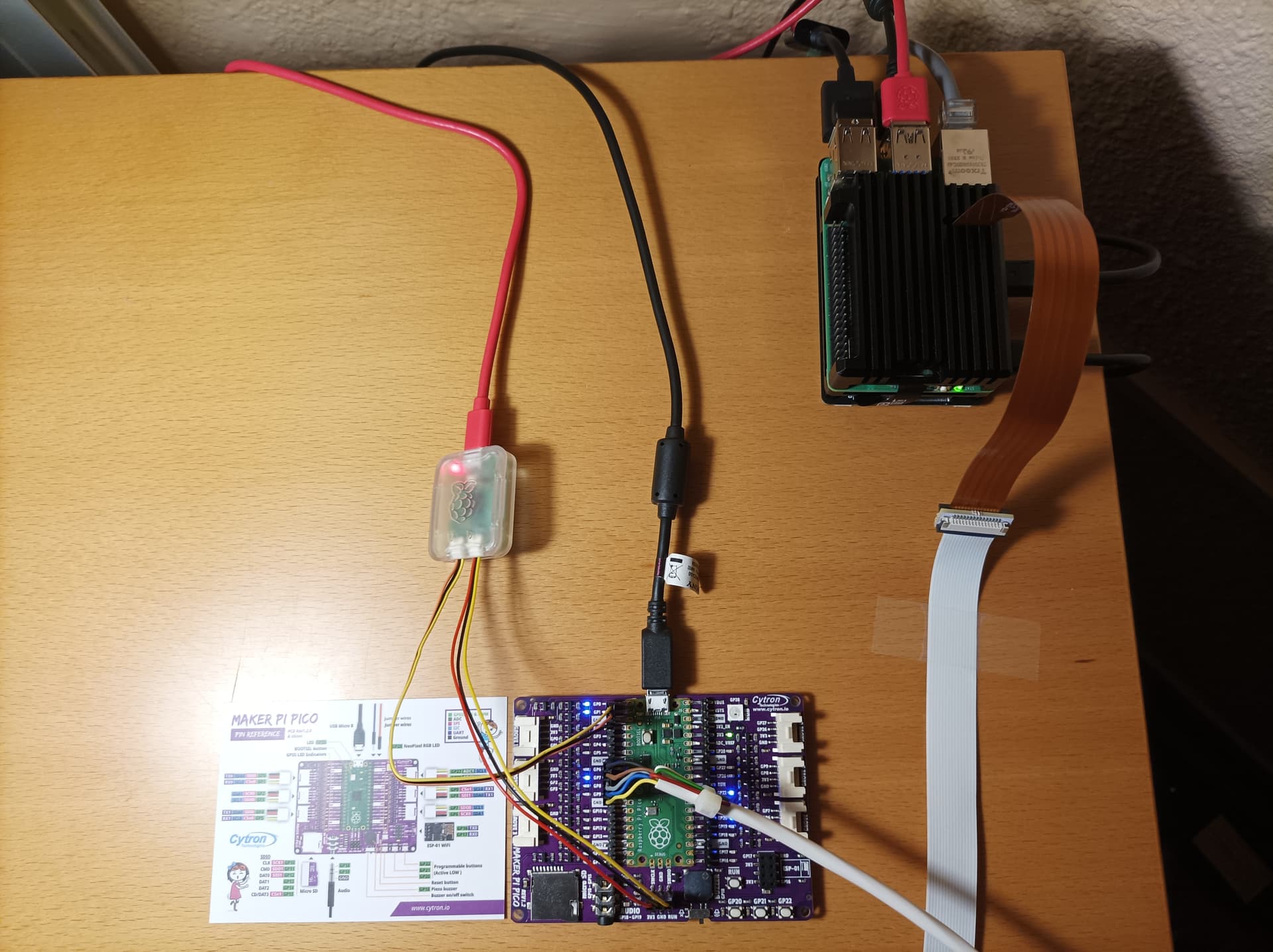
Throughout the week I hope to have a Pico to do the first tests. Instead of purchasing a bare Pico, I thought about purchasing this board that makes prototyping easier.
You are welcome. Hopefully this post and code will ease the control of single-stepper projects.
The document in the repository provides python sample code (forgot to include the import serial). Communication is one-way (RPi to Pico), except for the startup message to confirm that it is up (PICO to RPi).
If you prefer and/or are looking at doing other projects with PICO, the Board you linked looks a good deal, and more than what you need for the stepper. I saw that there is a version with the PICO on headers (instead of the PICO soldered).
The only minus I saw was that they appear to have the LED also on the pins corresponding to the PICO ADC, but that would be a factor only for ADC projects.
For this test, if you were using dupont-connector wires from the PCB to the RPi, basically only need to move those dupont-connectors from the RPi male-header to the Pico male-header (not even a prototype would be needed).
One item that you do need is a USB-A to USB-micro with data capabilities (not all charging cables pass data). It will connect between the PICO and a RPi USB port. The PICO is powered through the USB cable.
Until you get the tool-chain going, don’t hesitate to ask if you need to make any changes to the code.
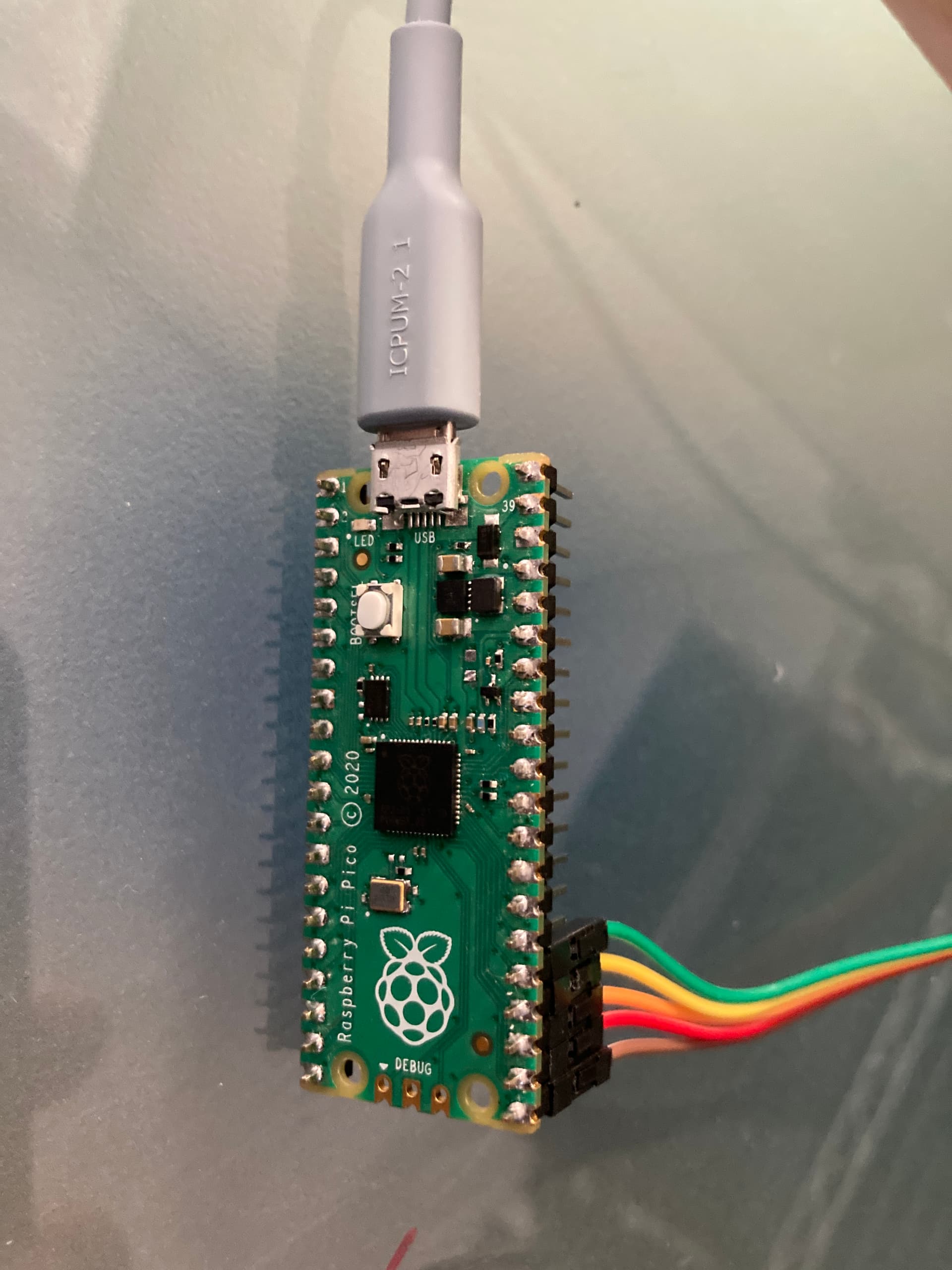
… here’s the one I am using. It has terminals as well as indicator LEDs, making it rather easy to connect to external hardware and checking basic IO-operations.
This is a quick video demonstrating the implications of using acceleration control. A lego is set on the capstan think of it as the passenger.
The first turn is with acceleration control. 1/8 of the turn accelerates from still to a micro-step period of 20 microseconds, 6/8 of the turn is constant at 20 microseconds, the last 1/8 of the turn decelerates from 20 microseconds to still.
The second turn is performed at a constant micro-step period of 20 microseconds, no acceleration control.
For both turns, microstepping is set to 256 per motor step (51200 micro-steps per turn). Controller is the PICO driving a TMC2208. The microstepping setting in the TMC2208 is done via UART.
@PM490 I want to take this opportunity to thank you for your idea of using Pico as a replacement for the GPIO interface on RPi5, in the absence of a compatible pigipo library.
The Pico PIO peripheral, with its state machines, seemed like a great idea on the part of the Pico designers.
It is perfect for stepper motor control. Each state machine has its own clock whose frequency is also programmable. The state machine works completely independently of the CPU, so timing is perfect.
I finally decided to use MicroPython for the software to run on Pico for motor and lighting control. At the moment I have not implemented engine acceleration control. However, on my device the movie movements are correct.
The RPi5 - Pico bidirectional communication was carried out using Pico’s UART0 through the RPi Debug Probe, with excellent results.
As you have very well commented, the use of Pico has the additional advantage of immunity against possible changes in future hardware or software versions that may occur in the RPi.
– let me note one important thing with respect to accelleration ramps: they can offer in fact a faster movement compared to constant speed movements, as you can increase the velocity of the stepper in the constant movement phase to a higher value without risking loosing steps. So while you waste some time accelerating and decelerating, it is made up again during the constant motion phase with a higher possible velocity.
Also, of course, the mechanical wear and tear of the film is reduced with accelleration ramps.