Well, DaVinci is a complex program and I might not understand it either to the fullest. But I think this is the way input data is inserted into the timeline:
-
The input node reads the data. There is the possibility to assign an input LUT to the data, on the “Media page”. I never use this. If this LUT is not specificed (the standard case), processing starts with the following step:
-
The input node pipes the data directly into the timeline. So whatever timeline space is selected is used for the interpretation of the incoming data. Under normal circumstances, incoming data will be rec709 or sRGB, and if you work with defaults, the timeline color space will be rec709/sRGB as well. So all is good in this case. No need to worry about color spaces. However: we did choose to work in
DaVinci WG- so the data from the input node would be interpreted asDaVinci WG- which is not correct. We need to get the data into the correct color space - this is the reason the first processing node in the clip’s processing pipeline is doing a color space transform (CST). -
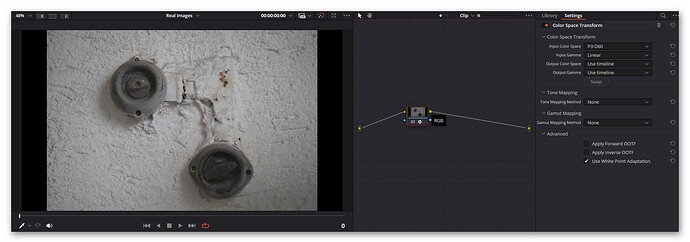
A CST needs two things: a specification of the input color space, and a specification of the output color space. Now, as we have set up the raw reader to output
P3 D60, this is the correct input color space for our CST. And of course, since we selected as gamma curveLinear, we need to select this as well in the input section. The output section just uses for both settings theUse timeline. So after the input CST, your data ends up in the correct color space. Which is the color space selected for the timeline:DaVinci WG. All processing in your timeline will happen in this color space. Note that you want to make sure that neitherApply Forward OOTFnorApply Inverse OOTFis checked and that both “Tone Mapping” and “Gamut Mapping” are set toNone. Be sure to checkUse White Point Adaption. This will shift the whitepoint from our input whitepointD60towards the timeline defaultD65(a minor change). -
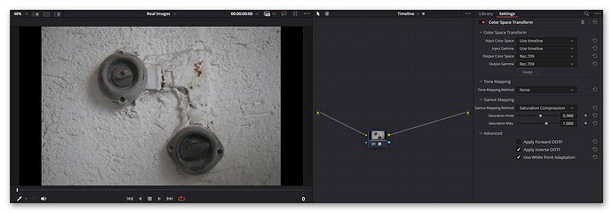
DaVinci WGis fine as timeline color space, but rendering out just like that is not going to work. The images will be dull and desaturated - even in preview. In order to be usable, you will need a secondary CST which will be applied to all data in your timeline after all effects. It therefore needs to be located at the very end of the timelines node graph (usually, it would be anyway the only node in this graph). This CST has as input theUse timelinesetting and as outputRec.709. Here, theApply Inverse OOTFneeds to be checked. I set the “Tone Mapping” toNoneand the “Gamut Mapping” toSaturation Compression. The later will gently roll off too high saturation values exceeding the output color space - this is exactly what I want.
Hope that clarifies a little bit the data flow. The raw reader pipes into the timeline raw data developed into P3 D60 - even data which lands outside this color gamut, as DaVinci is not clipping during processing (as long as you are staying away from LUTs). The CST following the input node takes all the data and aligns it to the chosen color space of the timeline. Since that space is larger than P3 D60, we in fact recover some colors which would otherwise be lost. (At least I hope so… ![]() )
)
But in order to grade and output the material correctly, we have to insert at the very end of our processing pipeline yet another CST - namely the one which maps from our timeline color space into what we want to grade into. In our case Rec.709. If my monitor wasn’t calibrated to rec.709 but rec.2020, for example, I could opt instead to map here into Rec.2020. Of course, I won’t, as most distribution channels currently support only rec.709 for sure - higher color spaces are always a gamble at this point in time.
Frankly, there is no correct color space for your .tiff-data. For starters, it still includes the blacklevel, so zero intensity is not represented by a zero pixel value. Second, there is no whitebalancing applied, so there is still the dependency on your illumination. Given, you can come up with a grade which mimics the necessary steps taken during raw processing - but only up to a point.
Well, it’s not really arbitrary. It’s just not as precise as we would like it to be. Cooling down a sensor chip for example changes the blacklevel - which more advanced cameras notice, as they use blackend pixels on the sensor for blacklevel estimation. Our sensor does not do it. Is it crucial? Probably not.
I do not think so. I have RP5 as well as RP4 machines capturing in raw and saving as .dng. Well, actually the .dng is not saved but send via LAN to a PC. Maybe that’s the difference. It’s been a while since I did this, might have to recheck this.
Yes, indeed. Usually, the red channel uses the largest gain multiplier. In my case, processing of .dng-files is never done on a RP, but a faster Win-machine.
Uh. That might be something interesting. But how do you do your color science than? Of course, grading by eye is always a possiblity…
Remember that libcamera/picamera2 delivers you a secondary, already processed image with basically no additional resource consumption (the “main” profile). You can pair that with my sprocket detektion algorithm posted elsewhere on the forum to get a real-time sprocket detection on a RP4.
Hmmm. I guess we have a different approach here. I only use the RP4/5 as a capturing device and do all the heavy processing on my WinPC.
![]() - that’s a big plus! I usually update a secondary RP4 and see what breaking changes were introduced by new picamera2 updates. Only after I am confident that I solved all issues I actually update my film scanner. Sometimes, as RP4 and RP5 are using slightly different software bases, I still get some unpleasant surprises after an update…
- that’s a big plus! I usually update a secondary RP4 and see what breaking changes were introduced by new picamera2 updates. Only after I am confident that I solved all issues I actually update my film scanner. Sometimes, as RP4 and RP5 are using slightly different software bases, I still get some unpleasant surprises after an update…
Yes. Not only that, but it requires to take into account the data in the As Shot Neutral-tag as well before applying the CM1. That is, the red and blue channel gains need to be applied before. And, to make things even more complicated, the CM1 transforms from sRGB to whitebalanced camera raw - which is the wrong way around. The matrix needs to be inverted to be useful. And, to make things even a little bit more involved: for the whitepoints to match, the matrix needs to be normalized in a certain way. Don’t ask me why… Oh, and I forgot: you need to throw in a CAT (color adaption transform) matrix in that box as well… (all this is and more is handled by any raw developing software)
Well, that’s my approach. The RP simply captures a frame and sends it as .dng-file directly to a Win-PC for storage, via LAN. Capturing a 15 m S8-roll takes about 3 hours with my scanner, as I have to wait long enough for vibrations induced by the film advance to settle (should not used plastic parts for my scanner…). Next step is DaVinci, converting the .dng-files to rec709-files, which takes about 30 mins on my PC (depends mostly on the hard disks). Raw development and some initial color grading is already done at this point. Data is output as rec.709 tiff-files. After this, a Python prg locates the sprocket position and removes remaining jitter (again about 30 mins). Next step (yet another timeline in DaVinci) is the final color grading of the footage, including cut out of the image frame. Rendering time again about 30 mins, less if I have space available on faster hard disks (which I usually never have…)
That’s actually the point I was trying to make: the scheme I was describing in my other post is exactly doing this. It converts captured .dng-files into rec.709 images, with sensible adaptions (the Saturation Compression in the timelines CST) if the colors are too extreme. The color science used (the inverse of CM1, essentially) is based on the optimizations done while developing the scientific tuning file for the HQ sensor.
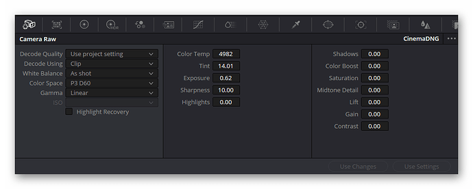
Here’s again an overview of my current setup. The clips are developed with this setting:
The clip input CST is set up like this:
and the timeline features this as CST setting:


