Raspberry Pi 5 GPIO

Hello everyone,

The new Raspberry Pi 5 incorporates a series of technical improvements that make it very desirable.
However, it also has some drawbacks. For example, it does not have analog audio output. The camera connector is different so the old cables cannot be used.

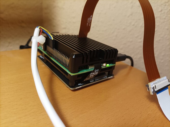
For my part, yesterday I finished building my RPi 5 with the addition of an NVMe base and a 2TB NVMe SSD.

I immediately observed a serious problem that I had no prior knowledge of.

On the GPIO port, RPi 5 uses very different hardware than previous models, so the old libraries do not work.
Such is the case of the pigpio library, which I use in my DSuper8 software to control the stepper motor and lighting.

In short, the DSuper8 server does not work on RPi 5. The same will happen with any other software that uses these libraries.

The only solution is for the authors of the libraries to update them to work on RPi 5.

Best regards

3 Likes

yes, the RP5 is quite a different machine than the RP4 (or: RP1, RP2 and RP3). Besides the GPIO-stuff the whole image processing pipeline got updated. So expect some other surprises if you switch from RP4 to RP5.

For starters, there are currently two different directories where the tuning files are stored. One is /usr/share/libcamera/ipa/rpi/vc4, this is for all the RP1-RP4 models. The other directory with tuning files is /usr/share/libcamera/ipa/rpi/pisp, and this exclusively is for the new RP5 unit.

I have not yet looked into the details, but for starters, there is (at least currently) no imx477_scientific.json tuning file for the RP5. This affects both people working with .jpgs/.pngs as output as well as people working with .dng (raw) files and the HQ sensor: the colors of the imx477_scientific.json are different from the standard imx477.json tuning file.

Another important change is that the RP5 uses “compressed” raw formats - that is probably something one wants to avoid in flim scanning applications. At least as long as there is no decent documentation on these formats available (they refer you to the uncommented source code…) I assume it works with a coarser quantization than the usual raw-formats.

There might be other surprises coming up – I suspect that the noise reduction algorithms migth have changed, as they are needed for the new HDR-modes available only on the RP5.

A positive surprise is that saving a .dng-file takes on the RP5 only about 0.2 sec, compared with about 1 sec on an RP4 – but only if you force the RP5 to use the old “normal” raw formats, not the newly introduced “compressed” formats.

If you do not specifically ask for that mode, the RP5 will use by default one of its new “compressed” formats, and saving a .dng will again take about 1 sec.

Why? Before the RP5 can save the requested .dng, it has to recalculate the original raw data by decompressing the “compressed” format it works with. That takes about the one second mentioned. The saved .dng-file is of course anything than identical to the original raw sensor data. For me, this is a rather hilarious approach to saving raw sensor data.

There might be other things like this hiding under the RP5-hood… - stay tuned…

2 Likes

Thank you for sharing, very helpful in deciding how/when to switch.

An alternative, is to use a PICO (between the RPi and the Stepper Driver) to handle the stepper, and it can also handle the LED control. The PICO would connect to the RPi5 via USB, and a simple serial-via-USB command would move the stepper or set the light.

I am currently working on cleaning my stepper driving with the PICO, happy to assist with prototyping the PICO software if you wish to give it a try.

2 Likes

Well, I am testing the RP5 right now as well. And indeed, steppers are better handled with a Pico. The timing is much more precise. As you described, the Pico is powered and commanded via the USB cable in my setup.

My LEDs are driven by a separate board connected to the RP5 via SPI - you just need to enable SPI in the RP-setup.

The Pico is just for the steppers (one film stepper advancing the film, two tension stepper for maintaing proper tension) and tension control. It feeds back signals to the RP5 which in turn forwards them to the scanning prg running on a WIN11 machine. This prg uses for example the left and right tension values to automatically stop the capture if either of one these values drops close to zero.

But of course, one nice thing about Manuel’s (@Manuel_Angel) software is that you only need one RP and one software. With the Pico as intermediatary, you need to maintain a secondary software for the Pico.

2 Likes

Agree…

Not necessarily. For builds like yours/mine, yes. For projector builds (like what @Manuel_Angel software typically is used for, the PICO can be dumbed-simplified as a USB-Serial to Step/Enable/Direction “hardware” block.

It gets a defined command, is makes a nice 1 turn ( different commands for Clockwise or Counter). It would also implement -if so desired- the ramp-up and ramp-down on the steps. Some of the PICO IO could be used to predefine the time of the step-pulse.

For On/OFF LED, it can also be dumbed down to one command changing an IO port.

Essentially the idea is a $5 “hardware” interface from USB-Serial to Step/Enable/Direction, immune to future IO Raspberry Pi changes.

I have seen many projector builds that use pulse generators and some mechanical or magnetic trigger to sense the turn… the proposed PICO alternative is a step above (if desired) without software maintenance complications.

If @Manuel_Angel is interested, I can cut and paste relevant parts in C into a software prototype (even compile it to drop into the PICO), just need a bit of info on what command/response would be desired.

EDIT: Maybe I miss something… but from all the code that I already have for controlling the Snailscan2 it should be easy to get something to test.

3 Likes

… that’s an interesting idea! Some commands to move a stepper (like “move(400)”), maybe even some setup commands (like “StepperEnable(GPIO26)” or “StepperDir(GPIO25)”) so that the output pins used can be set from the RP via the serial link. :upside_down_face:

Hi @PM490,

Thank you very much for your interest and your kind offer.

The truth is that I don’t know anything about the Raspberry Pi Pico or what languages it can be programmed in. I have always liked microcontrollers although I have never done anything serious.

In the DSuper8 server software, there is a module called controlProcess.py that runs in an independent process and whose functions, actually very simple, are done by the pigpio library/daemon.

These functions can be summarized in:

  • On/Off of the LED lamp.
  • Changing the direction of rotation of the motor.
  • Engine rotation in full frames. That is, for example in a frame advance order, it always advances one full frame. In the case of my device it would be a matter of sending a sequence of 3200 impulses to the motor driver.
  • Sending engine stop signals, to synchronize image taking.
  • Sending forward/rewind signals of a frame, to keep the film position indicator updated.

With the pigpio library, the motor rotation was done in a very regular and precise way, thanks to the use of hardware timers.

I think it’s a very good idea to use Pico for the moment. I am very afraid that the version of the GPIO libraries compatible with RPi 5 is going to take a long time.

I want to think that it won’t be very complicated to do these functions with a Pico, although I would have to start from scratch until I get something useful.

Best regards

There are 3 main paths to program the PICO:

  • Arduino IDE (similar to Arduino hardware, and similar issues with the IDE).
  • Micropython.
  • C, crossed compiled in Windows or Linux.

PICO has a storage-device mode. When you plug it into a computer while holding the little button, it will be seen as a storage drive. Drop the executable (from one of the 3 options above) in the drive, and done.

I am using C (actually C++ structure, but not all C++). The PICO has a very powerful IO system, and I am only using it in very basic ways. It is also very fast CPU.

Some of the basic blocks you will need are already written for the SnailScan (a bit more complicated than what you need). I will use those to cut and paste into a simple command parser to implement the above. It will help you get over the learning curve… I will provide a compiled/linked file that you can drop in the PICO via storage-device, along with the source files.

If you wish to make changes and add to it yourself, then you can consider setting up the cross-compile toolchain.

Do you have a PICO? if not, consider ordering one. You can use either the PICO or PICO-W, for IO they are the same (the W has the WIFI, but I have not used it yet).

I should get to work on it the next couple of days, early next week at the latest.

1 Like

Thank you very much for your interest and attention.

At the moment I am reading the documentation on MicroPython.

I don’t have a Pico yet, but next week I hope to get a Pico H.
For the application at hand, I do not see the use of WiFi as necessary.

Cheers and have a good weekend.

1 Like

Posted the PICO code in a separate topic, since it should be applicable also to hardware other than the Raspberry Pi 5 (this topic).

1 Like

Yes, it’s a shame that the excellent pigpio library doesn’t work on the PI5 but I think things will certainly evolve.
Personally I think that solutions based on pico or arduino remain complicated to implement. Why not recycle our excellent PI4s and stay with pigpo to control the steppers? We can imagine a network connection between the PI5 and the PI4 using the network classes of my yart project which make it very easy to send commands with their parameters.
Furthermore, with the increase in RPI5 performance, I no longer think that a client-server design is justified for the scanning application. On the PI5 running a PyQT user interface does not pose a problem and writing to an SSD is now faster than a network transmission!

1 Like

If you have a hammer, everything looks like a nail. My capabilities are skewed to microcontrollers and real-time, what you describe -for me- is step-years away :smile:

Fully agree. That in part was the reason for the effort to share the simple drop-in PICO Stepper PED block.

With the code shared, one would flash the PICO, jump 4 wires between the PICO IOs and the stepper driver, connect it to a USB Port (Windows, Mac, Linux, or Rpi), and with any terminal program (Putty?) can get the stepper moving from the keyboard… all commands are single character and human readable/typeable.

The learning curve of steppers plus PICO is steep, so hopefully it will serve as a big shortcut for DIYers to get some projects (single stepper ones) going a bit faster.

Hope it works out for Manuel, and let’s see where the it lands.

The idea of using another RPi (RPi 2, 3 or 4) to manage the GPIO port is undoubtedly another viable option, until we have a version of pigpio compatible with RPi 5, or another library with similar features.

The speed of NVMe SSD “disks” is truly impressive. They are light years away from the writing speeds of microSD memories. From this point of view it seems that the client-server architecture does not make much sense.

However, there are those who prefer to continue using their PC or Mac as their main computer and, in this case, this architecture is interesting.

I have to say that, although I have a couple of PCs, since I got the RPi 5 I have been using it as a desktop computer to my full satisfaction. What I like most is the absolute silence and low consumption.

For now, I am attracted to the idea of using a Pico microcontroller as @PM490 has proposed.

1 Like

Well, let me throw in the following into the discussion:

The Raspberry Pi’s from v1 to v5 are running usually a Linux-operating system – which is not too precise with timing pulses. The reason is that a lot of jobs are simultaneously active and you never known when a job with huge resource demands might kick in and slow down your program.

That is different when using microprocessors without an operating system - like the Arduino or the Pico. If properly programmed (using timer-interrupts for example), timing on the GPIO pins of such processors can be extremely precise. So if I had the choice, I would not use a RP for driving steppers, instead opting for an Arduino or a Pico.

While we’re at these processors: here’s a comparison of ADCs on ESP32, Pico and Arduino:

3 Likes

The PICO SDK is interestingly odd, since it runs at 125MHz and has a since boot us timer (microseconds) that never rolls over. I took advantage of this feature to simplify the code for the USB2PED code, by arming/waiting from edge to edge on an endless squarewave (busy_wait_until function). The GPIO changes are made after the edge with no variable-processing code, keeping these locked to the software timer. Other processing -which may be variable in time/cycles- will happen within the edges, always after the GPIO was updated. My oscilloscope is not that great (being polite), but the pulse timing looked very precise.

After working with Arduino Uno and PICO, the article is spot on. I found odd that many references in the raspberry forum confuse the PICO ADC values would have 16 bits range, even using the 65536 for calculations. In reality the value has a 12 bit quantification.

A summary of my findings of the PICO ADC:
For precision application, it is useless as it come out of the box.
To make it work:

    1. Remove R7 at the PICO board AND provide your own 3 Volts reference at ADC_VREF (pin 35).
    1. Use AGND (pin 33) for all circuitry related to the ADC signals, do not use other GND pins.
    1. Condition reference and signals to mitigate very high frequency digital noise.
    1. From RP2040 datasheet: the maximum ADC input voltage is determined by the digital IO supply voltage (IOVDD), not the ADC supply voltage (ADC_AVDD).
    1. VSYS can be accurately measured by ADC3. To do so it requires configuring the PICO GP29 (adc_gpio_init) as one would with ADC0 to ADC2.
    1. PICO core temperature can be measured with ADC4. Use adc_set_temp_sensor_enable(true), no need to perform an adc_gpio_init().
    1. All ADC measurements use the same ADC_VREF (see point 1 above), meaning that calculations for VSYS and core temperature should be adjusted according to the exact value of ADCVREF.

With the above you’ll get a great 10 bit resolution ADC, and a decent (if not great) 12 bit one.

PS. I was just going to comment about it… ended up typing a PICO ADC cookbook :smile:

1 Like

…read and understood your code in your github-page. While I am an old C-Programmer and I can thus appreciate your approach, I opted, for my own amusement, for different approach: Micropython.

Now, Micropython poses certain challenges for the task at hand: for starters, the maximal timer interrupt frequency you can achieve is limited to 1 ms - which is way to slow for fast steppers.

So I realized the task by using a PIO-processing block of the Pico. Basically, that block gets the delay to the next pulse as input. Once the PIO has issued that pulse with the timing requested, it waits for the next delay data. The data for the next delay is fed into the PIO by a chain of three coupled DMA-channels, realizing acceleration, high speed phase and deceleration. The ramps are adjusted, depending on how many total steps the stepper is expected to move.

As Micropython for the Pico does not yet feature a pre-cooked DMA-interface, some bare-bone programming was required - however, it seems that there will be a dedicated DMA-interface upcoming in some of the next releases.

The code works, but it is still work-in-progress (as I am waiting for the DMA-interface to surface).

This approach has the interesting property that both CPUs on the Pico basically do nothing to drive the stepper, as instead dedicated hardware (PIO + DMA) is used, which even have their own memory interface. So the CPU can be used for other tasks (in my approach for handling the command interface and tension control).

Running the PIO at a base frequency of 2 MHz, I can output pulse trains of max 4.5 kHz to the stepper driver (that give me a frame advance time of about 0.25 sec in my scanner). Ramping up to 16 Mhz, I measured about 32 kHz pulse frequency. The frame advance in this case is so fast that I would not subject any film to that.

Comparing C(C++) vs. Micropython, the C-approach seems to be much clearer to me. In the Micropython approach, you have to do a lot of obscure configuration work – that might be easier to handle once a standard DMA-interface is availble. Still, the Micropython implementation is far better to understand than my old Arduino-implemation (C++), where I needed to program the hardware timers directly.

Debugging/developing within the Micropython context is much easier than with what I am used to in the context of C-programming. There are still some oddities in Micropython. For example, you can use the Pico as an I2C master (to read from I2C-sensors, for example), but – as far as I know — the Pico can currently not work as a I2C-slave (simulating an I2C-sensor for another master, like the RP5).

Yes, that’s funny. Probably a design decision by the Micropython team to make code more portable between different microprocessors. I still have 8-bit-ADC-ICs in my part bin and for certain applications even these are fine…

1 Like

@cpixip
Yes of course it’s all the difference between software or PWM hardware, also depending on the degree of precision sought for the application. On an RPI the pigpio library was I think “quasi hardware” and that’s why it no longer works on the PI5. In any case Manuel and I did not notice any problem controlling the stepper with pigpio (In reality I also think that the basic, totally software solution (GPIO+wait) as in Joe Herman’s initial project in a separate process would work also ?? )

@Manuel_Angel
Really if I had to start again on a “blank page” I think I would abandon the idea of the “client-server” application. Obviously it is entirely possible to control the Pi’s graphic interface from the PC and of course the images will have to be transferred to the PC for all subsequent processing.

@PM490
Everyone has their favorite “hammer” and their hardware or software orientation. For me really too much hardware and complicated programming with these micro-controllers, depending of course on the goal to be achieved.

2 Likes

Hi @PM490,

I haven’t been able to test your software on the Pico yet.

I have a Pico available and have done some testing with an RPi 4.

On the RPi 5 I have installed the toolchain, but it has the peculiarity that the UART and SWD interfaces are not accessible from the GPIO port pins.

I am waiting to receive a Raspberry Pi Debug Probe to access the UART interface and flash the Pico.

Regards.

1 Like

Hola @Manuel_Angel, no worries take whatever time you need.

I have not used a Debug Probe. There is a setting in the CMake file to allow the USB-Serial Input/Output, and with that setting, you can create print commands in your code for debugging. This video is a good overview.
Note this project makes use of these settings

# Enable usb output, disable uart output
pico_enable_stdio_usb(${PROJECT_NAME} 1)
pico_enable_stdio_uart(${PROJECT_NAME} 0)

Not sure I understand what you are trying to do. The idea is to connect the flashed PICO usb to the USB of the RPi or PC.

If you already have a PICO, you can follow these steps for a quick test:

  • Download the file PICO_USB2PED.uf2 at the flash folder in the repository.
  • Press and hold the Bootsel button (button next to the usb connector) then connect the pico to the PC (while holding it pressed). After is connected, let go of the bootsel button. The pico will show in your PC or RPi as a storage device (similar to a usb-drive).
  • Copy the file PICO_USB2PED.uf2 you downloaded to the storage device. That will flash the PICO.
  • The storage device will then disappear, and the PICO is now programmed.

The PICO will now act as the USB2PED. Reconnecting the PICO (without pressing the Bootsel button), will add a Serial port to your PC or RPi. That’s the serial port you connect with.

To test manually, any serial terminal can communicate with the added Serial port (the Pico connected to a USB port).

Check what port was assigned by the PC or RPi. In the RPi 4B it typically is assigned /dev/ttyACM0.

For the Terminal program (I use Putty Serial) use the following settings to connect:
Port = /dev/ttyACM0
baudrate = 115200
bytesize = 8
stopbits = 1
parity = N

Once you are able to connect via the terminal program, typing the letter-command will allow you to see/test the results on the corresponding GPIO pins.

L - will make GP19 (Led) High.
l - will make GP19 (Led) Low.
E - will make GP18 (Enable) High.
e - will make GP18 (Enable) Low.
D - will make GP17 (Direction) High.
d - will make GP17 (Direction) Low.

And if you have something you can see pulses with (a scope or logic analyzer)
T - will send the default one-turn number of pulses out of GP16 (Pulse).

See the PICO_USBPED Documentation for all the commands available.

That’s a simple first test. Also note that commands are actually quite easy to follow L for LED, E enable, D direction, Caps → High, smallcap → Low.

If you have the above working, wiring the PICO to the stepper driver (via your PCB) would allow you to manually move the stepper.

To make a turn, the key sequence would be.
d or D (depending on the direction of turn)
E (to enable)
T (one turn at the current frequency and number of steps)
e (to disable driver).

Once you have the above working, then use the Python example in the documentation to get your program to send the commands for your software.

Let me know if the above is clear, happy to address any questions you may have.
EDIT: added baudrate to the settings.
2 Likes

Thanks for the detailed explanations.

My idea is above all to use your software to “break the ice”, but later I would like to master the programming of the Pico in more depth.

For now I have followed this guide which I found very accessible and educational for a beginner.

The RPi debug probe allows, with the appropriate software, to access both the UART serial interface and the SWD interface from any computer.

The SWD interface provides a very convenient way to flash the Pico, without needing to disconnect the USB cable or press the bootsel button.
It also allows you to debug and run the Pico code from a main computer, all via software.

Regards.

1 Like