Short question: How have any of you communicated between the Raspberry Pi and an Arduino?
Hi folks,
In 2018 I completed an open loop design with just an Arduino, which is documented elsewhere on this forum. As always, thanks to the community for all the wealth of information that is here.
I want to try the next version, which will continue to use the Arduino for transport control of the reels and positioning each frame. I want to add a Raspberry Pi with a camera module (like others, I plan to start with the HQ Camera, since I have two dozen C-mount lenses here and there- don’t ask.)
This will allow me to use Python for the control to capture each frame, and then process the stills into a video using ffmpeg (as a starter). Obviously, I have not done any of this before.
So, my question is this- what have any of you used to communicate between the R-Pi and the Arduino? Any thoughts and link resources appreciated.
If this helps, my needs are “simple”- the R-Pi signals to the Arduino to move to the next frame and waits. The Arduino works away, controlling the stepper motors and sensors. When it gets somewhere, the Arduino signals back that either the next film frame is ready for capture, or that the film has run out, or broken, or some other error. Then it waits till the next signal from the R-Pi.
For context, this is an intermittent motion capture design.
Cheers,
Pranab
1 Like
Hi Pranab !
I’ve built my scanning machine with Rasp Pi and Arduino. I think there are many ways to do it but mine differs, just in the logic, in that the Arduino is sending orders to the Raspberry and not the opposite.
I have a laser sensor for holes detection and a stepper on reception wheel. The différents stages are:
1_ Stepper moves till the laser go through the hole. When the cell reach the threshold I’ve decided in my laser setup (it helps me to works with negatives, reversals and very clear sides as I can “tune” the threshold easily by reading the serial plotter in Arduino IDE)–>
2_Stepper stops →
3_Arduino give the order to Raspberry via USB connection to capture with Rasp HQ cam, in serial communication, via a Python code (for example (Raspberry Pi Arduino Serial Communication - Everything You Need To Know - The Robotics Back-End)) →
4_Wait 2s (for the file to be saved as DNG on External SSD, that’s what slows my machine down…), this is a delay command in the Arduino code →
5_Stepper move a little (some steps), so the laser is again on celluloid and no more in the hole
_and again 1
to process the stills I use Da Vinci Resolve after the capture is made as I use the stills a lot for my photographical work, it’s free, has an amazing tracker to stabilize the frames, and read DNG directly (that’s the most important for me… I put the folder directly in Resolve… the only problem is that Resolve don’t work at 18fps for exports… When I really need it, I use Blender that allows you to export at any framerate you want, and stabilize well (there is a tutorial about Blender somewhere in this wonderfull forum). Or now, I export from Resolve in ProRes and change the framerate in blender).
It’s a slow process but it works perfectly (for my needs, of course sometimes I wish it could be quicker), but in my system, the Rasp Pi don’t send any signal to the arduino, the arduino works as a “stand alone” and give order to capture.
I hope it helps a little 
Cheers,
Gregory
1 Like
Pi uses 3.3V and Arduino 5V. I use a cheap level translator from eBay and just send the pi a pulse when I want it to take an image. In the pi I include a small delay to allow film to settle, take pic and add another delay to ensure pi has completed task. Then send pulse back from pi to arduino to enable the next frame.
Thanks, Gregory. Yes, this is what I was looking for as a starting point. With this communication setup I can decide how to send codes back and forth between the two.
Thanks for the DaVinci Resolve upvote- I use it extensively. I wanted to explore if the entire chain can be contained in the film scanner, so am thinking of what can be contained in the R-Pi. At this point that is merely an experiment to be tried.
Cheers,
Pranab
1 Like
Thanks Pat. Yes, that is certainly an option for simple triggers, and I may try that out, if I can restrict myself to one or two pins. Have not looked at pin budgeting yet- was planning to use the Arduino with a 3-stepper motor shield to run the film transport. So, if that works, great. Otherwise I’m sure an Arduino Mega should give us enough pin freedom.
One thought- a bit more complicated to plan out, but using two pins can allows us to send 4 codes in one direction, and two more pins to send 4 codes in the other direction. All of these are experiments in my mind, currently.
I did want to try closed loop, with one device explicitly sending a message/pulse that it was ready for the next step.
Cheers,
Pranab
Not sure if you had a look at my system:
https://forums.kinograph.cc/t/my-scanner-arduino-pi/1949/2
I use 2x uno & cnc shields. Main reason is simplicity, one uno looks after the takeup and back tension and is independant. The other drives the film advance motor and takes care of the reference pulse from the encoder. I need that pulse to be an interrupt but if I put all three motors on the same board I cannot use the interrupt pins 2 or 3 as they are used for the stepper drivers.
The cnc shield has several analogue and digital lines available for other use, check actual connections with a meter as not all shields are wired the same… been there. Generate your own schematic right from the start to avoid head scratching later. If you need to send more data then I2C is available on two unused pins and can be connected to the pi via a level changer.
Cheers
Yes, - love the footprint as well.
I like the idea of independent takeup and back tension system. For the first version I had handled everything on one A-Uno through programming a detailed state diagram. Took me a couple of shots to get that to work. That is why this “delegated” model comes to mind, like you have used.
Cheers,
Pranab
We moved house a couple of years ago from a 4 bed to a 2 bed. I had to cram everything into this 10’x7’ room so space is at a premium. Once I have digitised my films the system need to be stored so the main board is removeable hence the plug socket system.
Hi,
Just came to know e-con Systems has recently launched the Ultra HD 4K 13MP MIPI CSI-2 Camera for Raspberry Pi 4.
Watch this video to know more: 4K High Quality camera for Raspberry Pi | 13MP MIPI CSI-2 Camera for Raspberry Pi 4 | e-con Systems - YouTube
This Raspberry Pi High Resolution camera is based on 1/3.2” AR1335 CMOS image sensor from ON Semiconductor® and has a dedicated, high-performance Image Signal Processor (ISP) that performs all the Auto functions like auto white balance, auto exposure control in addition to complete image signal processing pipeline that provides best-in-class images and video and the optional MJPEG compression.
@Gregory_Dargent I may have already asked you this, but do you have documentation on your laser setup? I’d love to see it. I’ve been testing sensors for the same purpose and the ones I’ve been testing work wonderfully but are expensive.
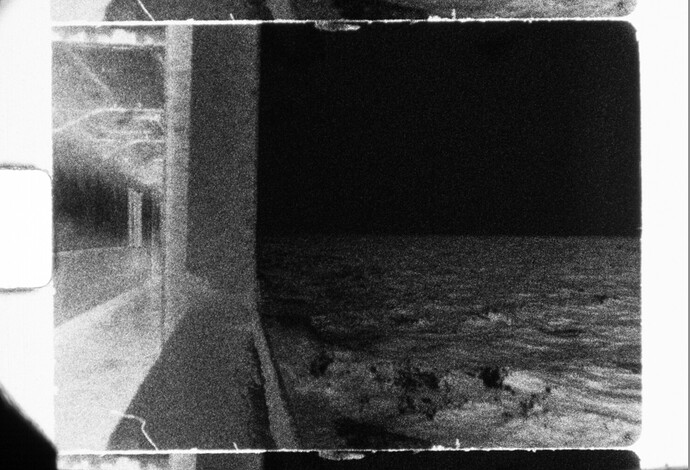
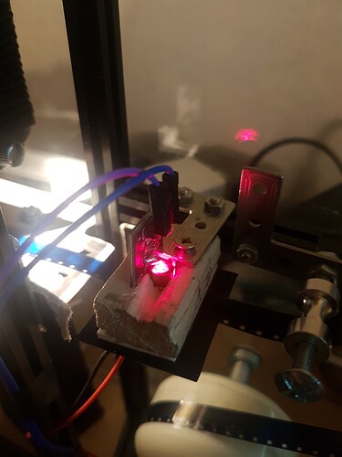
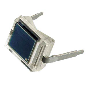
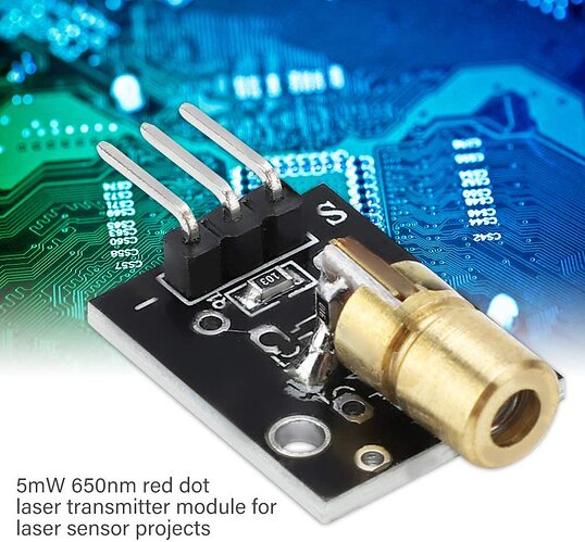
@matthewepler My setup is simple and cheap, through the hole (no reflective) (sorry for my english): A bpw34 silicium photodiode (0.50€) and a basic laser 5mW 650 nm (2€). I’ve made a pinhole and build everything with what I had at home, it’s ugly but it works perfectly, even with black and white negatives (here is an image.. the telecine is working right now with expired Moviechrome so I can’t stop it to show the laser, and an image for b&w negative
)
The cell is sending information in an analog input from my arduino. I can read the serial plotter to see for each film what is the dynamic range between hole and film and then, I put it in my code and for the moment, everything work very very fine.. and for… 3 €. I had a more expensive laser that was great (Laserfuchs, 14€), but…well… I burned it… 
This works for me perhaps because I’m in intermittent motion… the film moves slower, perhaps that changes something. An other thing I’m building right now is an optical read, to read opticale sound (like in projectors) but to use with seismograms (as waveforms) to recreate a sureal sound of the earthquakes, for an installation (mmm.. yes… lockdown make me have some strange ideas), so.. a laser, a slit and a bpw34. An for my experimentations, the more expensive laser works better than the cheap one, there is less diffraction of the laser beam, I guess… that’s all I can say for the differences…
Laser and diode if it helps:
This is great thank you so much. I’ll try to recreate that for a test with clear-sided film.
1 Like


