RobinoScan RT 16/35 Scanner

Hello everyone, I started building my 16/35 scanner recently and wanted to share my progress with the community.

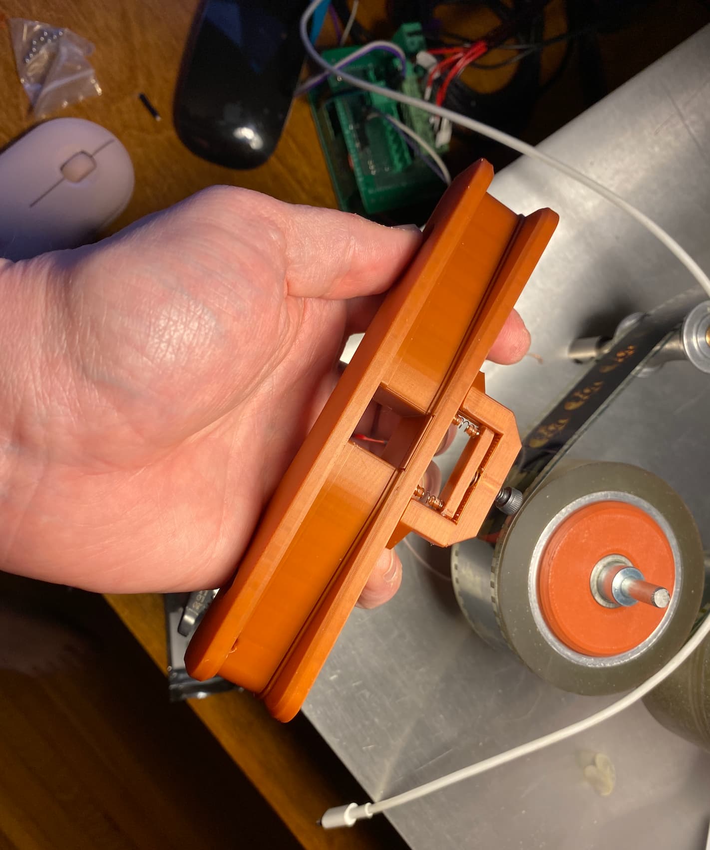
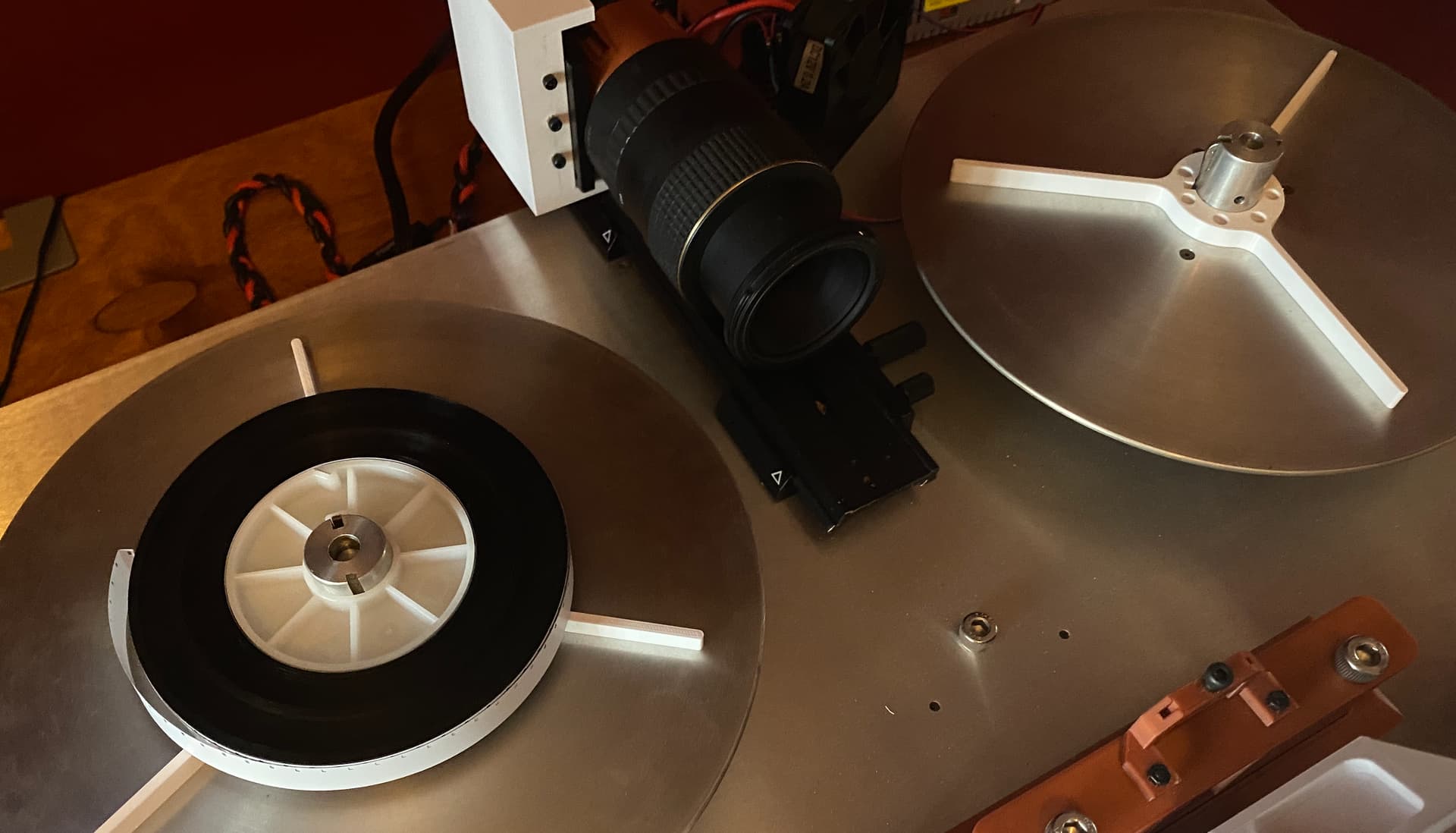
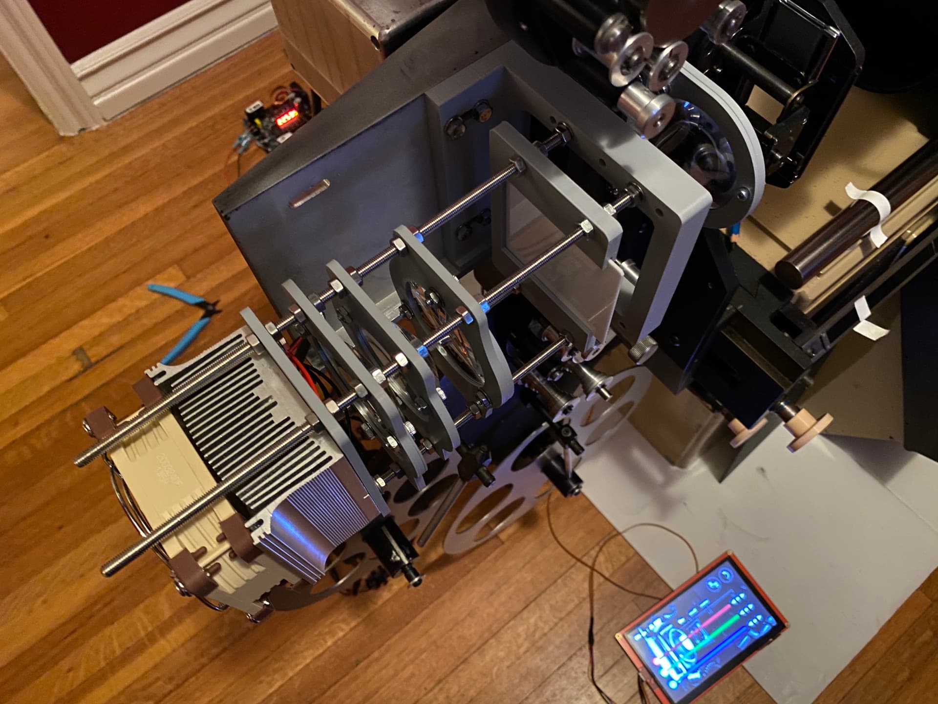
I just finished hooking up the film transport controls tonight, the drive system is an ODrive controller with 2 brushless motors + encoders, the tension is well controlled at any speed. Controls are hooked through an Arduino who sends ASCII commands to the ODrive. There’s still a bit of refinement to be done with motor tuning but it works well enough now to move on to the next step (Gate design and trigger). It’s a direct drive system, reels on the motor shafts.

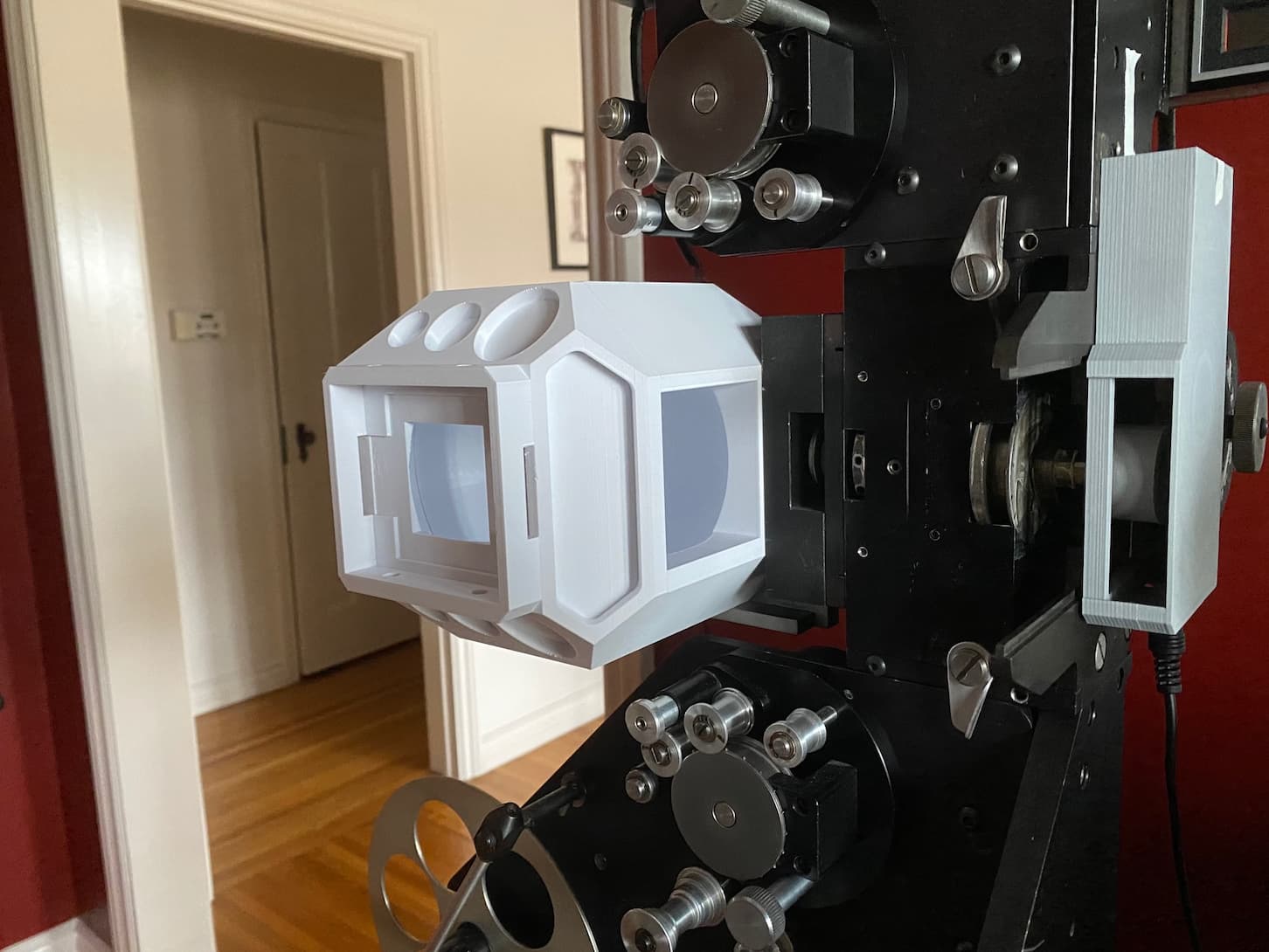
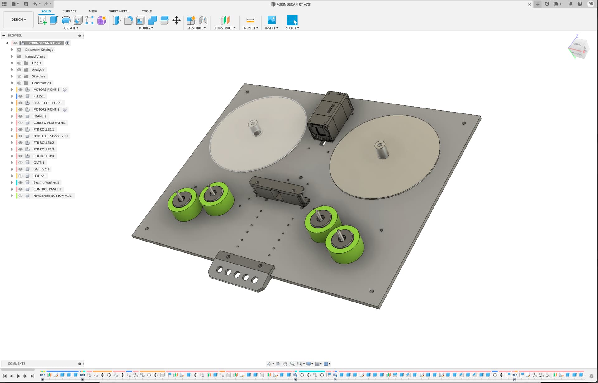
I’m going for a “Turntable” tabletop style with a removable acrylic cover to protect from dust when scanning. For the rollers, I’m using PTRs (inspired by Kinetta) because I like the simplicity, and I added 2 rollers on each side to help guide the film.

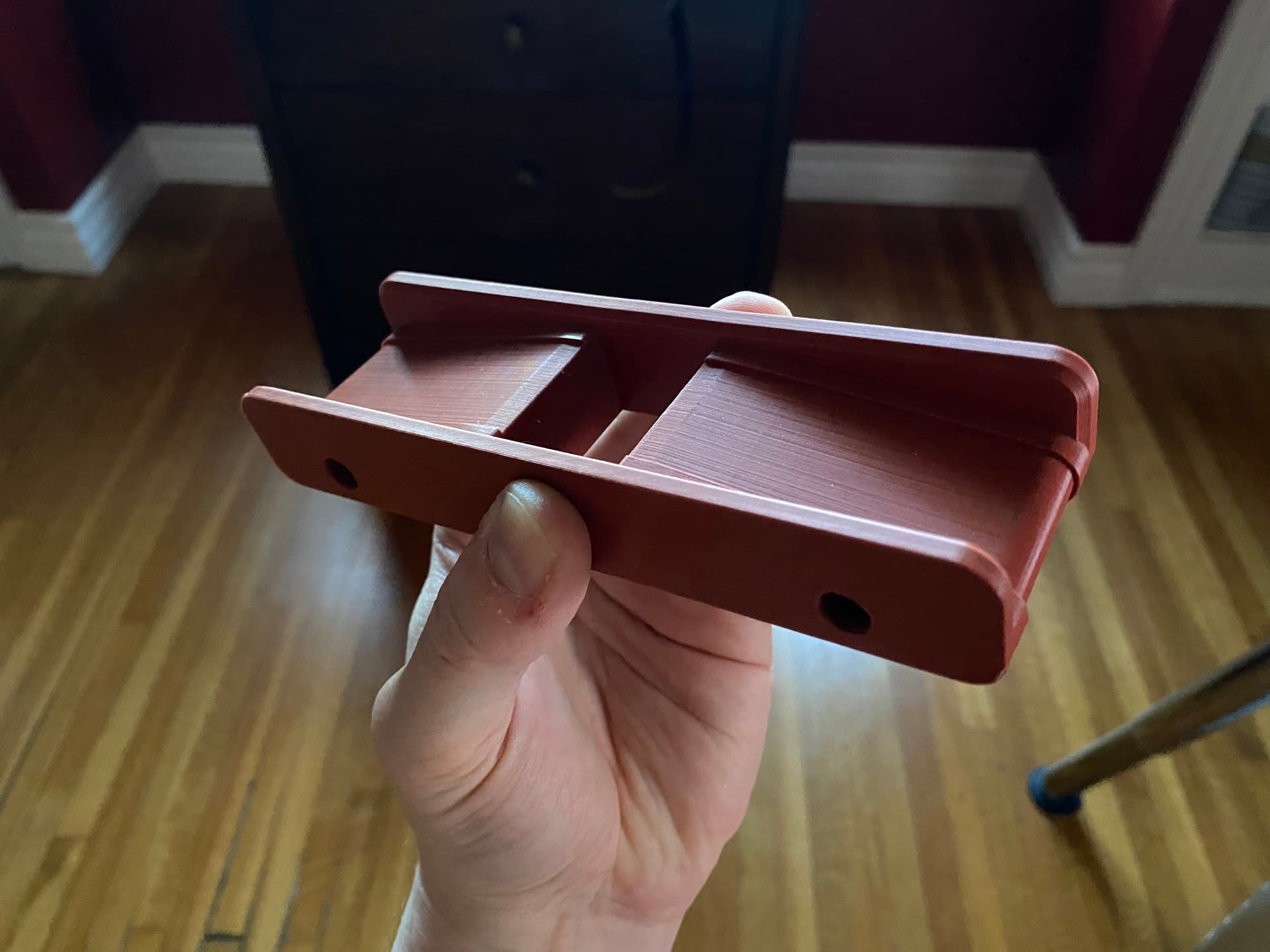
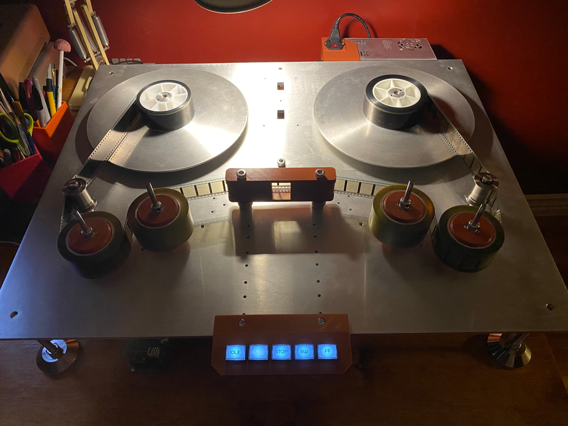
The controls are temporarily bolted on the front but in final design they will be embedded on the left side in the top plate.

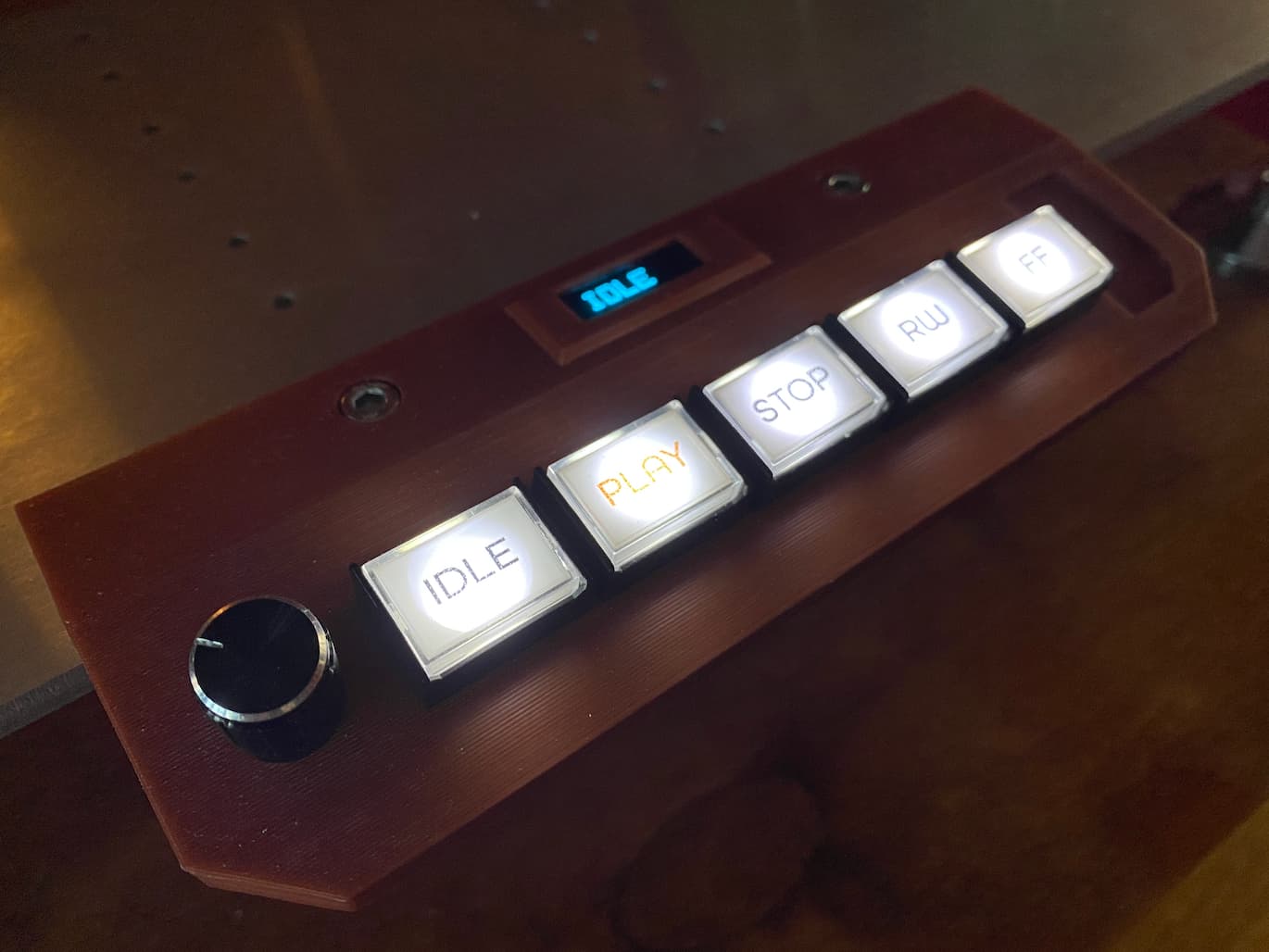
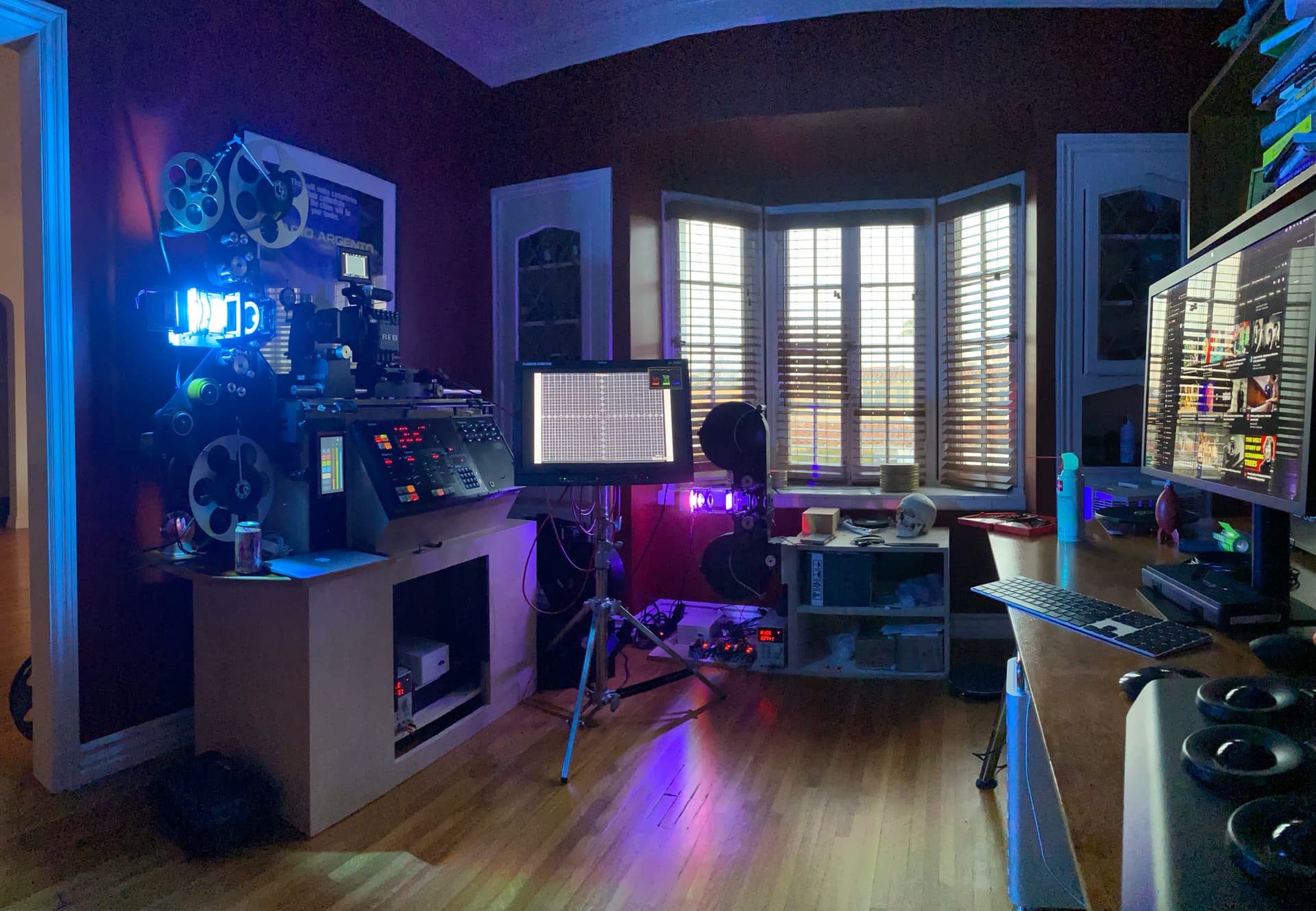
Here’s the build so far with controls installed.

…and a video moving film. Exciting to be able to use physical buttons, it was tiring entering terminal commands :slight_smile:

Password: robinoscan

As the design evolves, things will move around a bit so I made extra holes to help prototype.

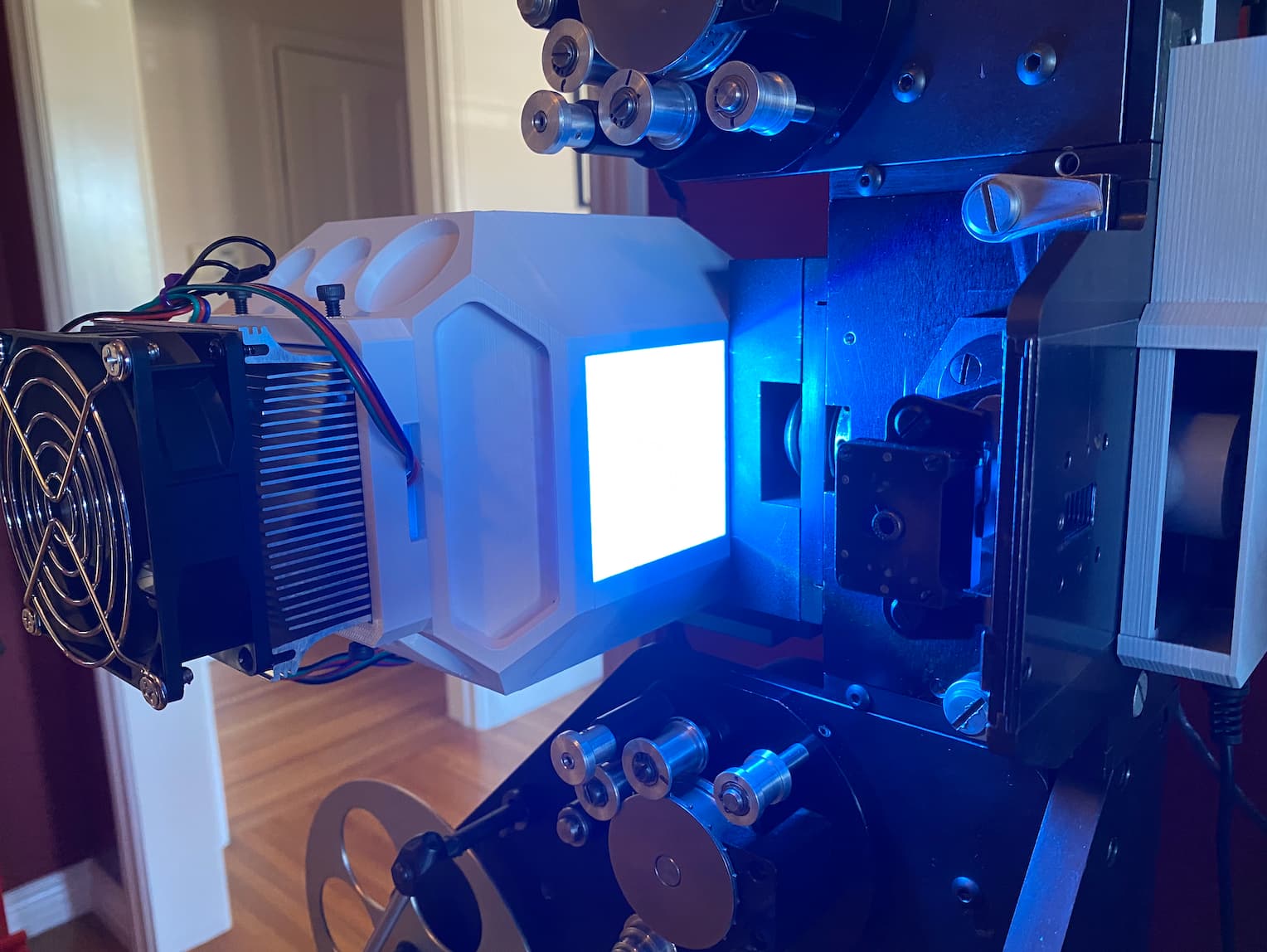
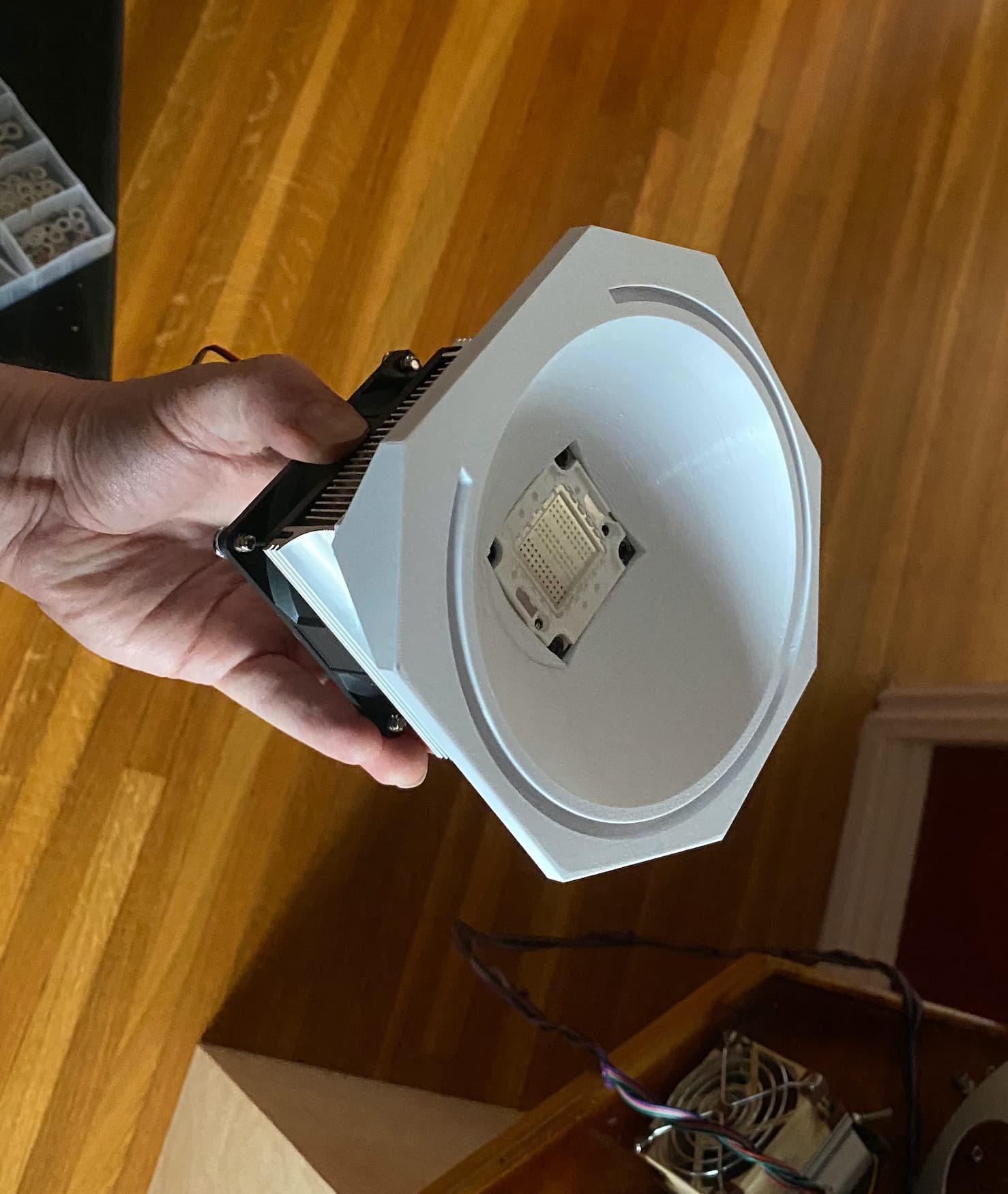
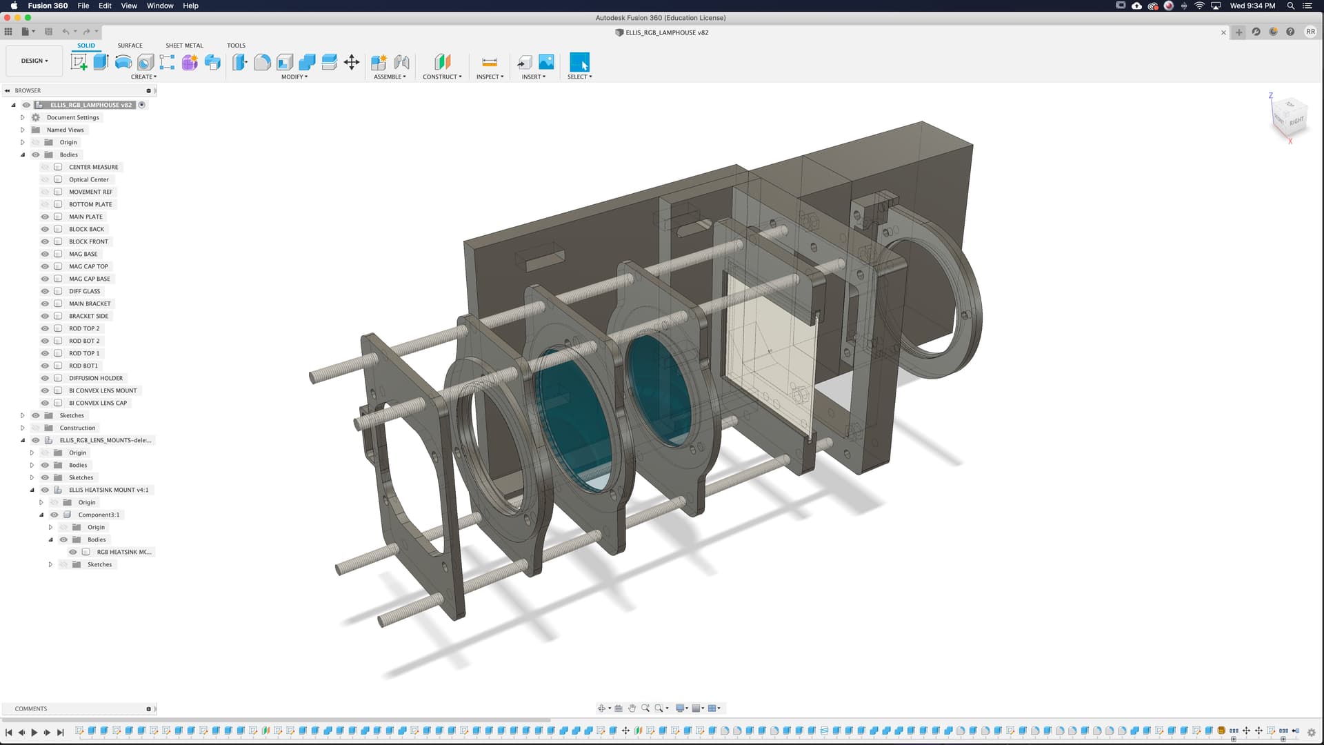
I started working on my integrating sphere. The top part is the heatsink mount for the RGB chip.
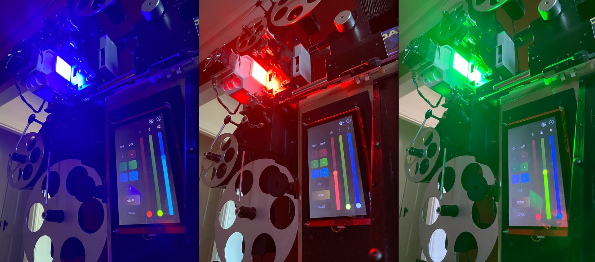
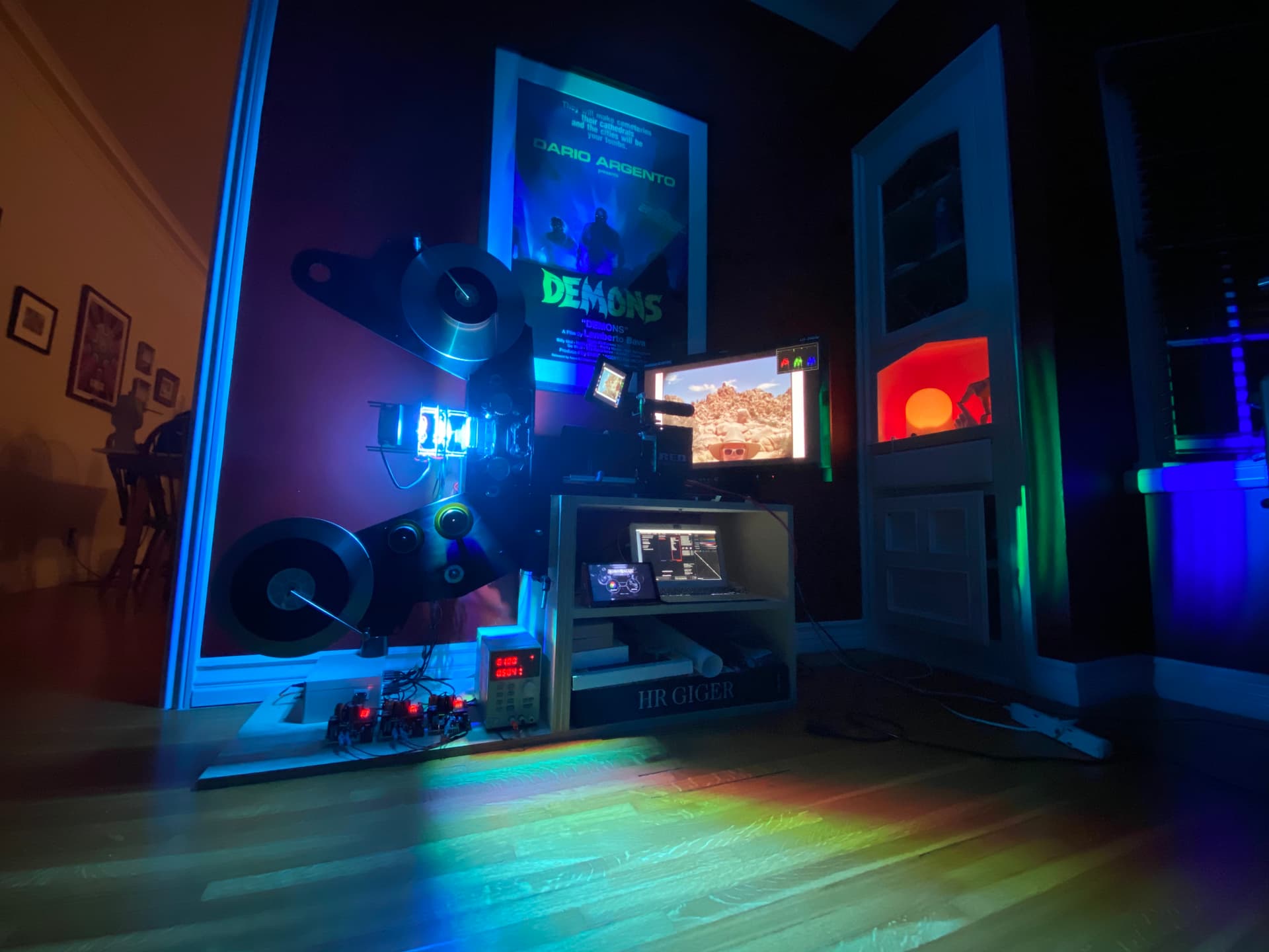
…but for now, I will be re-using the same light system I built for my optical printer scanners. There’s great work being done by @matthewepler and other forum members on light systems that are very nice and maybe I could migrate toward that eventually.

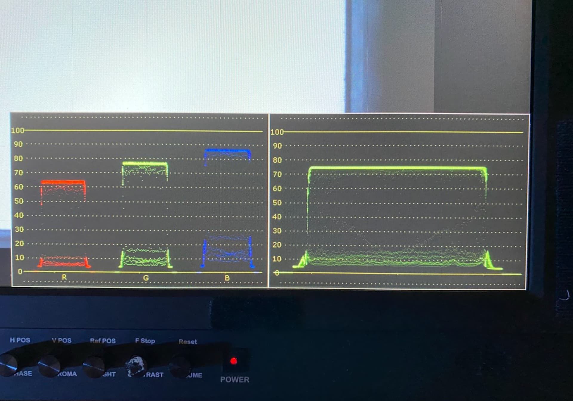
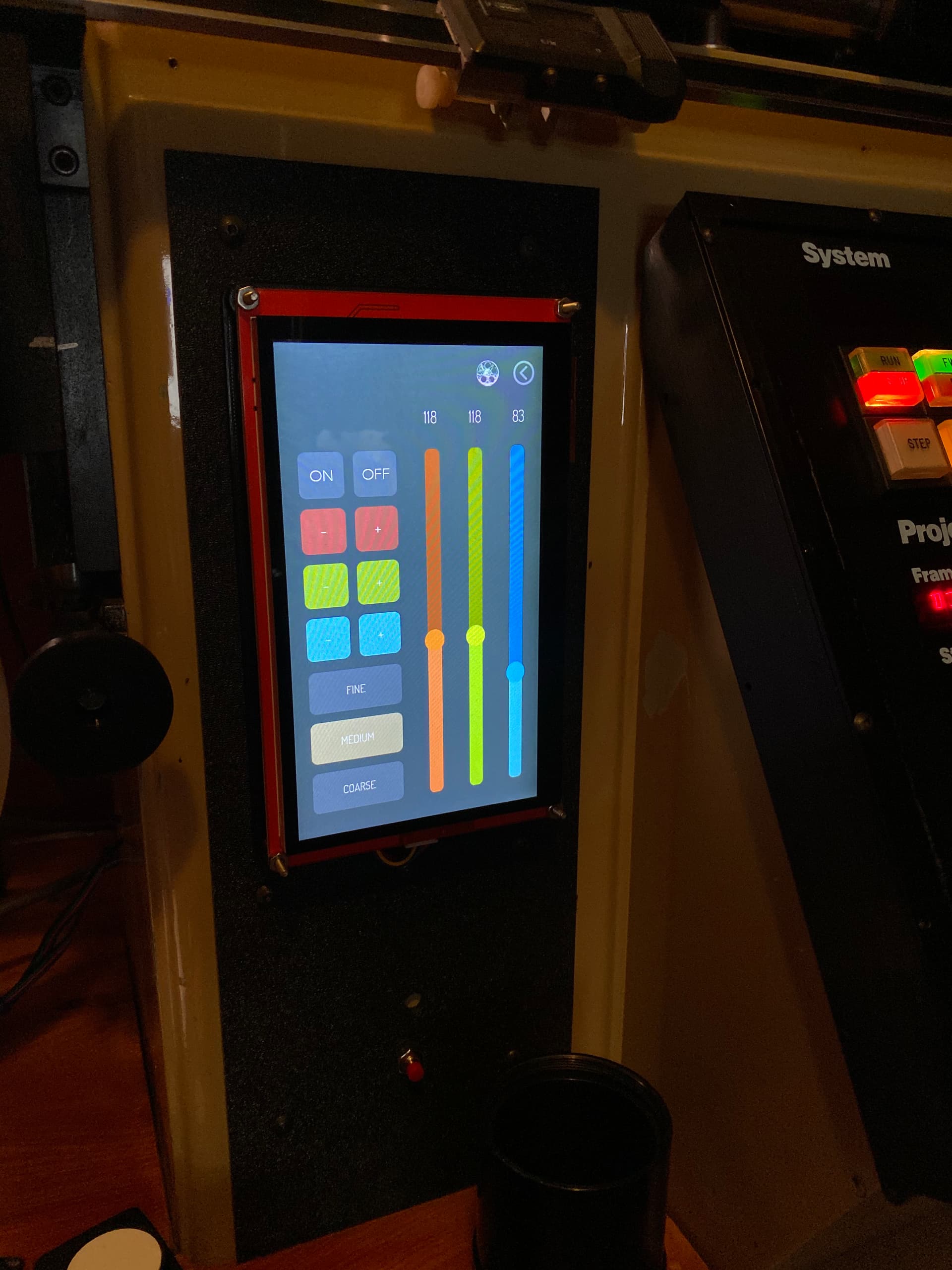
This is the light system I made for my optical printer scanners with touch screen RGB controls / 100W RGB chip.


I got the Keyence amp and sensor that @matthewepler recommended, I’ll be installing it this weekend.

For the camera, I’m planning on using the FLIR Oryx 10G / Model: ORX-10G-245S8C, let me know if that’s a good choice it will be my first machine vision system.

8 Likes

@robinojones,

Congratulations on the excellent work that I think is truly professional.

Pardon my ignorance. I would like to know what is the impressive machine that appears to the left of the last photograph.

Regards.

No problem! This is a bi-pack optical printer with custom controls for special effects work. I use it for scanning and also opticals.

1 Like

Cool design!

I can’t tell what your gate looks like, but the ones in the commercial machines have the window at the top of the gate not the bottom so that may be one thing to think about later on, the main thing is to get the film nice and flat and the light even. I assume you’re going to mount a laser for the sprockets, I’d be very interested to know how you advance the frame if you do as that could assist others.

The camera will need a fan dissipate heat, I’ve sent you a photo.

The current gate is a temporary one, I made it so I could work/test the film path & transport controls but now I have to design a better one with edge pressure plate and sensor mount. The window is at the top of the gate. Have to say even this temp gate appears to flatten the film very nice because of the curvature in it.

Yes I got the same system that was discussed somewhere on the forum I can’t remember. It’s the Keyence FS-N41P amp with the FU-20 sensor. Now the ebay seller I got it from sent me an older version of the amp (FS-V21RP) so I have to deal with that… It’s ok though I can still work this weekend and use this older model to set up since the FU 20 will not change.

The film is driven with the ODrive controller and brushless motors as outlined in the top post. The plan I’m thinking is connecting the sensor to Arduino for displaying frame count and triggering the camera but the Arduino might be too slow?? I have no idea, this is what I will experiment with this weekend.

Oh and if anyone is getting ODrive let me know I can share what I know and could also use some help with intricate / advanced coding…

2 Likes

I’ve used the keyence sensor output to an interrupt pin on the arduino. I just run a couple lines to update a count and set the camera trigger pin to high, it works well so far just with my basic testing :slight_smile:

I’ll be using the Teensy 4.1. It has pins that can be used as counters. Check out this post on the Teensy forums.

@Andyw in my testing the Arduino interrupts were too slow for speeds 12fps+ but I’m a space cadet amateur and that may not mean anything at all :slight_smile:

@robinojones I got my ODrive and I’ll be attempting to set it up this weekend. Let me know if you’re around for guidance!

I’m around, email me and we can arrange some time to go over everything.

Oh that’s good to know. I’m hopeless at programming so don’t worry. I didn’t get my motors running that fast to find that out. I better look into another solution!

Very keen to see how this ODrive system works out.

Small update -

  • Have a new scanner frame and top plates coming in soon, had to re-design it so I could lower the camera a bit and also accommodate for larger reels, right now my platters are limited to 1200’ but I want to be able to swap for larger ones.

  • Decided on the 5.5K FLIR camera, trying to talk to a sales engineer at Flir is very DIFFICULT.

  • Added a tiny LED screen and rotary encoder to display/select frame rates and scanning modes (4 perfs, 3, 2, 16mm etc)

  • While a wait for new frame and camera I designed the backlight and installed it on my main optical printer. It’s very powerful and super flat. See the scopes screenshot.


Using 100W RGB chip and my old control box with touchscreen, the coating is 10% Barium Sulfate + Titanium white flat liquid acrylic paint from Golden. Very happy with the result of my backlight, much much superior flatness compared to my older design that used condenser/focusing lenses.

3 Likes

The 5.3K Pregius S IMX530 is the best one (is that the one you mean, it’s what you mention in the OP). If you’re finding Flir difficult, this one will also work. I think it costs about $5K which isn’t that much more than Flir’s price.

I’m very interested to see results from your new rig it looks beautiful and very promising!

1 Like

Yes sorry I meant the 5.3K - typo, I will get the camera next week.

I did get a quote from emergent but it was a bit more expensive and also would need extra hardware (pci card and expensive cables ) but it’s 25GigE which is very fast. Wondering if the 10GigE interface is going to be fast enough to push 12bit full res at 24fps to a hard disk?

I was not able to ask a sales engineer about it - can’t get through them at all which has been frustrating. I got a reply from Graftek (a FLIR reseller I did not even asked for) and they were vague.

FLIR has a 30days return policy so I’ll use that if all is fails.

Are you using a mono camera and sequential RGB lighting, or are you using a bayer camera? If bayer, you could always capture the raw image, which should be pretty lightweight. 10G ethernet should be plenty of bandwidth.

Yes bayer / color camera

Thanks for the info - each frame will be 5320 x 4600, good to know 10Ge should be able to handle this in raw.

So I’m a little confused: Bayer mask cameras are always color. Sequential RGB setups would require a monochrome camera (not a bayer camera in mono mode). So it can only be both if you’re swapping cameras.

sorry for confusion - I understand the differences, been tired lately and wrote dumb dumb stuff by mistake.

1 Like

Post Xmas update - making scanners is hard!

The camera is installed, not final but with a cheap rail and 3D printed dovetail. Once everything is working I’ll splurge on a good rail and Y Stage.

Ran into issues with camera smearing, original plan was to keep the light on and don’t bother flashing, but this did not work with my camera - I have a feeling it’s not just my camera, I guess we’ll know when some of you guys start setting up your cameras. I had to synchronize the LED flashes with camera exposures. Purchased a 2 channel oscilloscope, without this tool, I would never have never been able to figure that out.

The pulse system is a retro-reflective sensor(Keyence) sending pulses to TTL line of camera, The camera then sends pulses back via GPIO opto line out to an Arduino Mega who then sends PWM signal to DAC board “DC2197A”

…who then sends analog voltage to Picobuck LED driver. The timing is done using in camera delays and counters (for 4 perfs capture), I also have control over the pulse length in the Arduino code.

With this solved it was time to scan something and I was having a hard time getting started with Spinnaker SDK. It’s not friendly at all, to me at least. And thanks to @matthewepler for helping with Python we almost got it to work.

Until I found this software called “StreamPix 8” from NorPix.

They make this machine vision image / video capture software that is compatible with a LOT of cameras and is packed with features. Some I was dreading having to figure out on my own. Things like video scopes (especially RGB Parade) which are essential when calibrating your LED lights before a scan.

It’s pricy, 1K for the software. I’m a 2 weeks trial and using it for capture and debayering. So far so good and honestly I might buy it to save me some headache and get a headstart on scanning. I really would like to get back to shooting and forget about making scanners for a bit…

Here’s a first scan (done last night) of random shots from an old S35mm negative test roll.

**

You can watch in 4K if you click the vimeo icon… i think in browser you can’t even go full screen…

**

https://vimeo.com/660515988

Also made a 16mm gate and platter risers (“a la Northlight”)

16mm scans are also going good.


NEXT STEPS ARE:

  1. MORE LIGHT. I need more light, pulsing really lowered the intensity so now have to figure out how to “overdrive” the LEDs. The pico buck is not going to cut it, it’s limited to 36V and 1A per channel. I had to replace 2 tiny resistors per channel to get to 1A per channel… they are TINY. I got 3 new drivers from TI.

Now the issue with these drivers is that I can’t turn them off! At 0 (LOW DUTY) the DAC outputs 002.5mV which I guess is enough for the LED DRIVER to turn on the LED, albeit at very low intensity… this was fine with Picobuck since the range is 25%-100% or something… but these drivers are full range. Need help with that.

  1. Need faster debayer. Streampix is nice but post debayering is around 1.5 ~2 fps when saving a sequence to DPX 10bit. It defeats the purpose of real-time scanning if you have to wait that much time to save a sequence. Will be talking to them to see if it can be faster.

  2. Perf stabilization. Right now I load DPXs in Resolve and do the stabilization there as well as the negative inversion and grading. (I also use Photoline for creating base inversion luts - the level tools are the best I found in image editing software)

So when points 1,2,3 are solved I will consider this a working machine and start design on final frame.

Right now it works, and pretty well for what it is, I really like the camera / resolution - with more light it will be so much better! I currently have to gain the camera to around 11db which I don’t like. Can’t wait to be able to blast those LED flashes at high intensity.

4 Likes

OpenCV has debayering built in and is likely as fast as you will find. It’s worth figuring out where your slowdown is though. I would be surprised if it’s in the debayer itself, and not in something else like I/O, especially if it’s high resolution. The actual act of debayering is not especially intensive, so it should be fast. If you can, build timers into your code at the beginning and before/after each individual operation. Then you can display the duration for each task and see where things are getting bogged down.

This would also be doable in OpenCV. One method is to create some template B/W images of just the perforations for each type of film you’re scanning, then have OpenCV use its pattern matching tools to locate the perfs in your image. Then you can determine where that perf is in the frame and simply move the whole image on the X,Y axes to align it to a predefined position. It should be very fast. We did some tests on 14k images a while back and the time it took to do the pattern match was measured in microseconds. One thing with OpenCV - you generally want to work on a copy of your full color image, that’s monochrome, so that processing is faster. then apply whatever transform you want to the full color image before outputting.

OpenCV has really good python integration, and most of the documentation and example videos you’ll find will include both C++ and Python code.

3 Likes

That’s great to know - I’m really new to Python and OpenCV and I can’t find much examples out there. OpenCV doesn’t read raw files natively, have to use Numpy or something. I got a snippet of code that read and saves an image but the image comes out all garbled. Will continue hammering at it. As far as IO i have a 24TB Pegasus 3 raid - it’s pretty fast.

When testing other solutions, I tried debayering with FFMPEG which was working but it was SUPER slow even on my MacPro NVME SSD, I think openCV will solve that.