SnailScanToo or 2

MID 2025 UPDATE

PICO Faster
In February the RP2040 and the PICO were certified to run at 200 MHz. I had been procrastinating on using the newer tool-chain for the PICO, and decided to do it an take advantage. When running at higher speeds, some things ran smoother, so I suspect that some of the real-time stepper related items had been near the limit (at 120 MHz).

Life got on the way and unfortunately did not progress as much as I would have hoped… but some small changes made real improvements.

New Rollers
In testing at higher speed, I noticed that occasionally the film edge would appear to bind to the roller edge, particularly in the larger diameter (~28mm) rollers that I had printed. The issue appeared to be a combination of the angle into the film groove, and possibly the increased angle creating support/drooping issues on the print (I do not have the best 3D printer). Additionally, I noticed that the film dynamic was different, compared to the transport with all-smaller-diameter rollers. The amount of larger diameter rollers, and the increased weight had a noticeable effect. To narrow the gap between the capstan and the roller, I also wish to make the larger diameter (32 mm), leaving a very narrow gap, and potentially more weight. The reason for the larger rollers is to reduce sharp curves to protect the film from breaking.

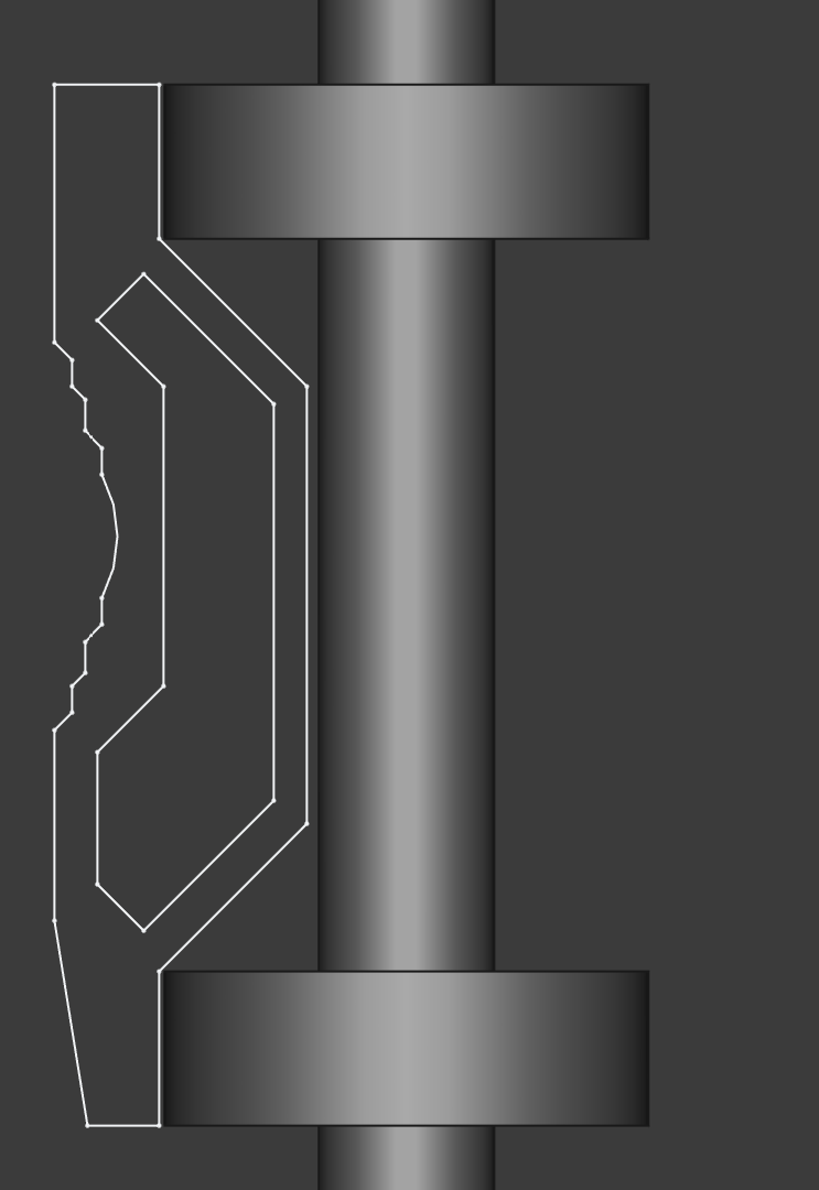
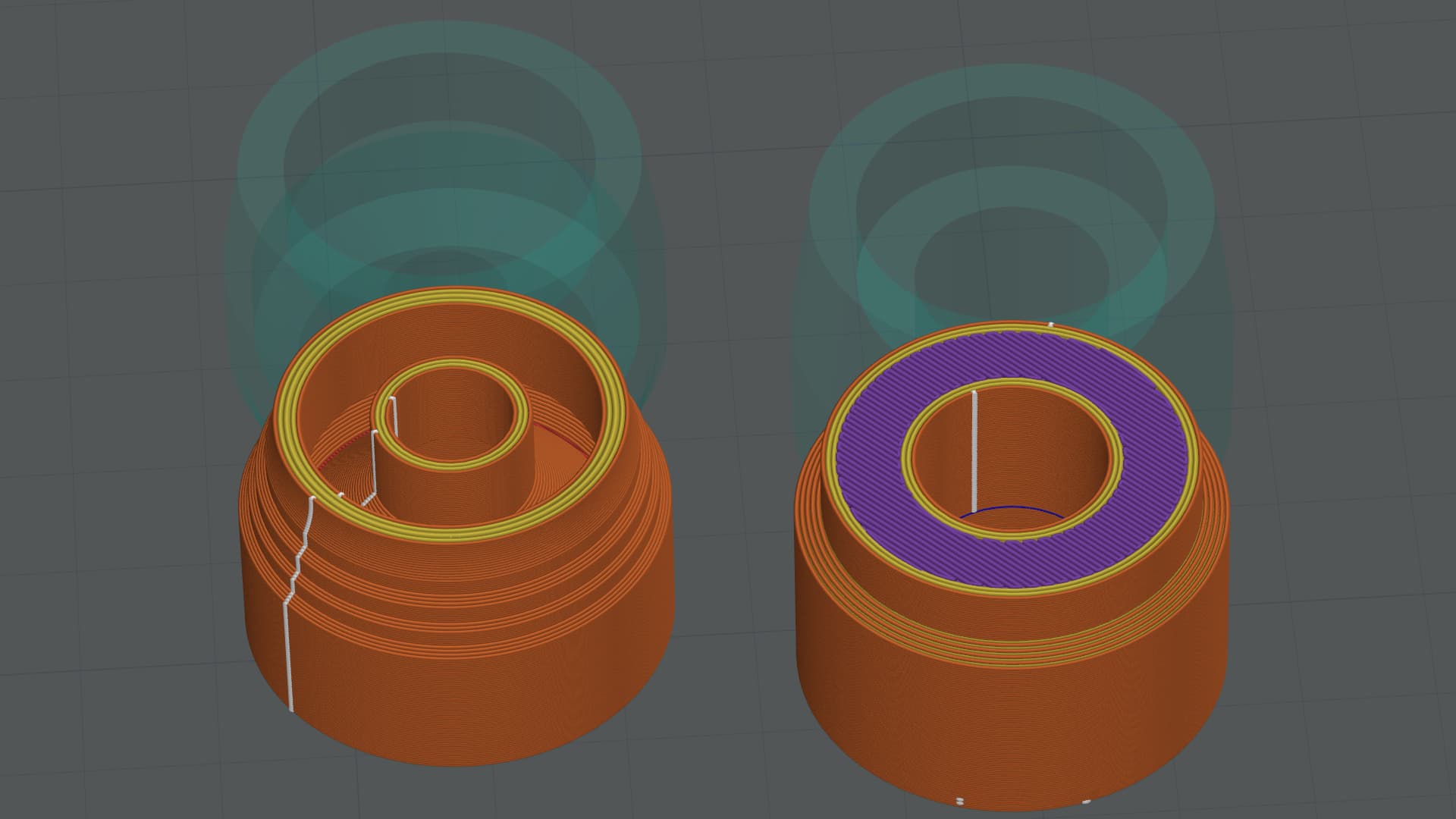
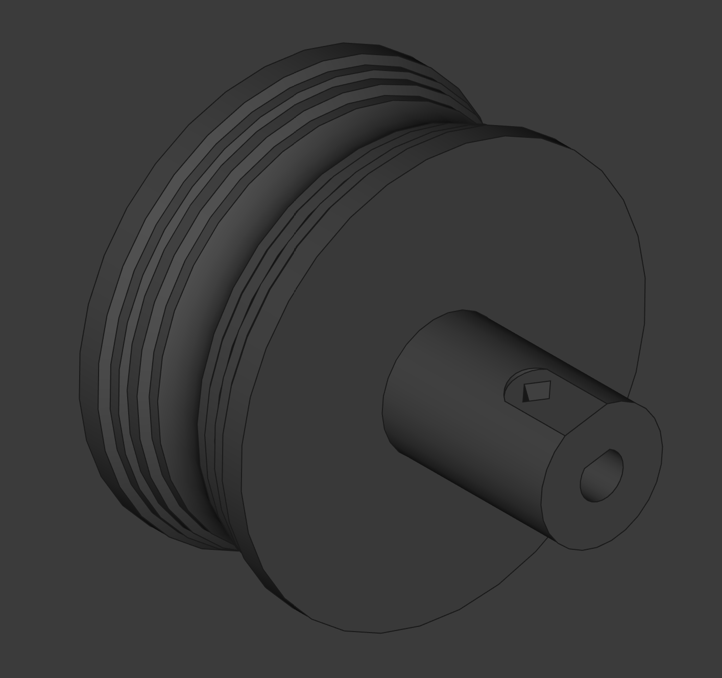
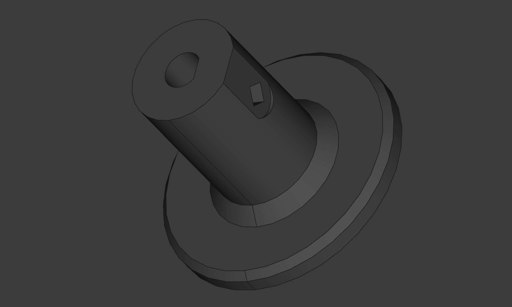
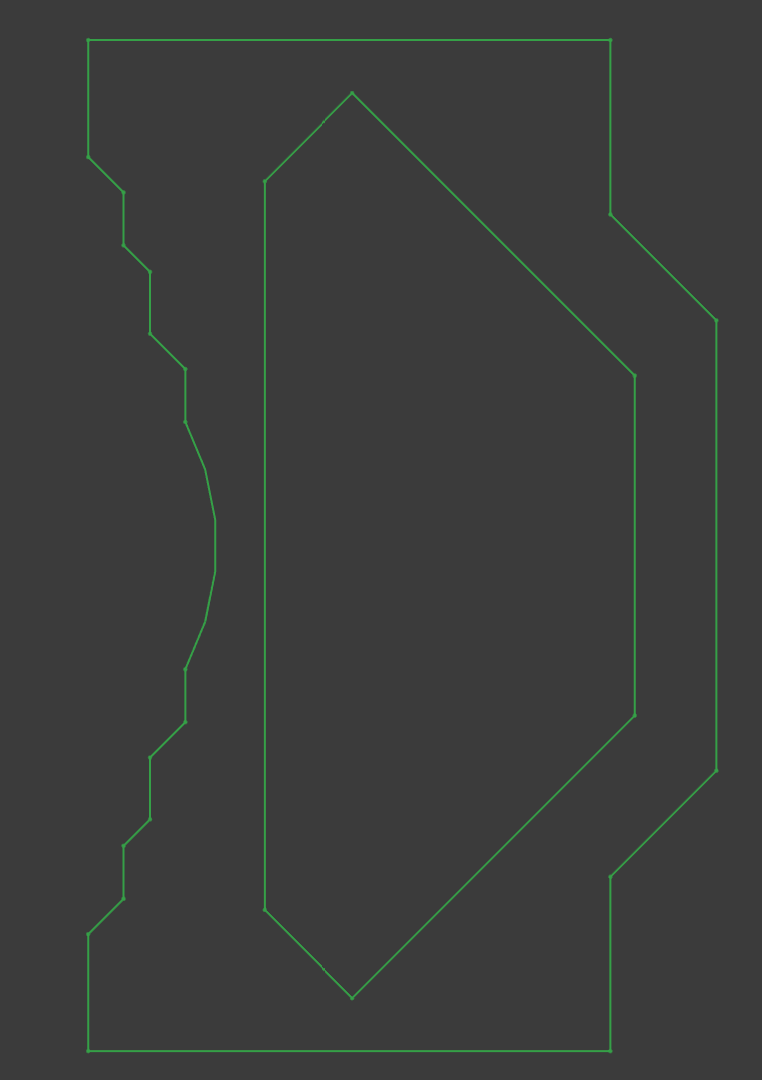
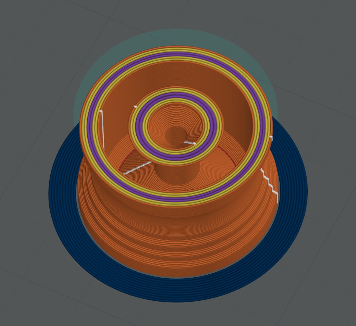
To address the above, it was time to redesign the rollers. This time the angles were constraint to 45 degrees on the film edges, and the inside of the large roller was hollowed. The V shape hole inside eliminates the issues with 3D printing support.

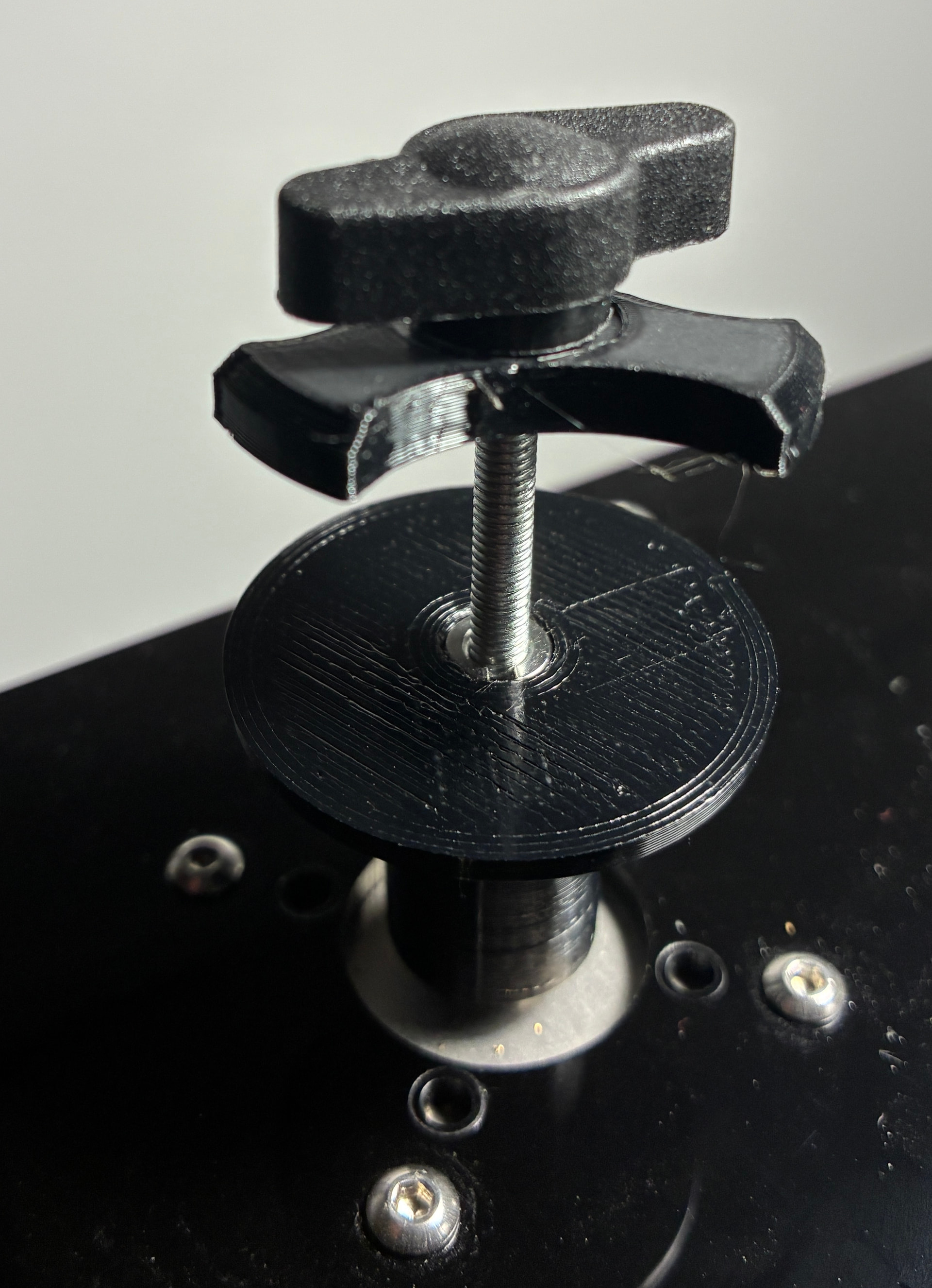
Here is the shape used to revolve the larger diameter guides (now 32mm diameter and slightly larger than previous). The idea dramatically reduced the weight of the guide, -according to the slicer- from 23.5 grams (with a 27.7mm diameter) to less than 10 grams (with a 32mm diameter), while keeping the same outer shape.


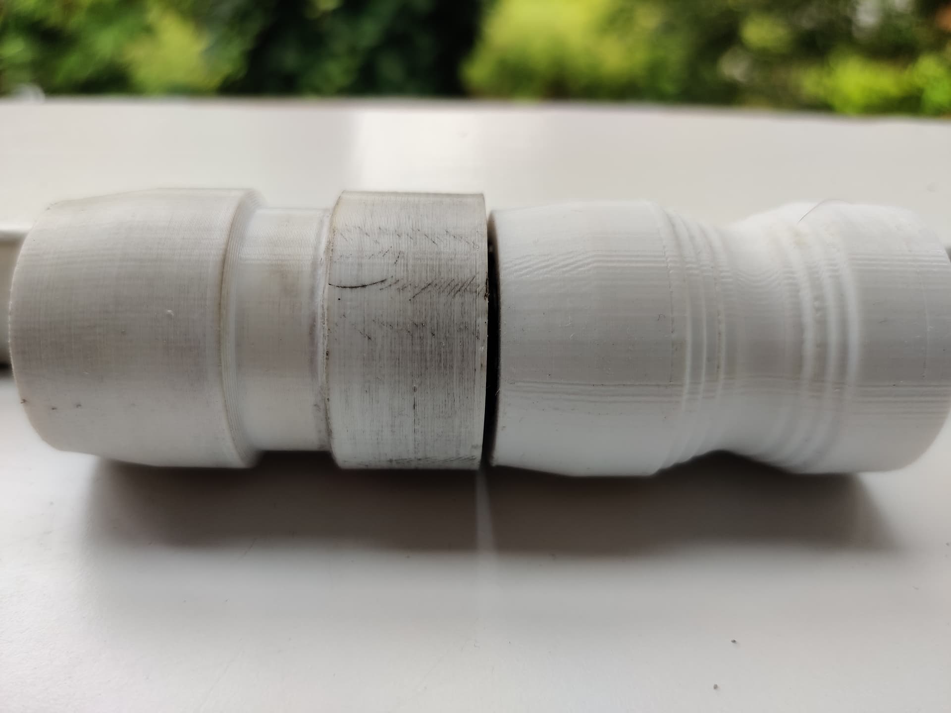
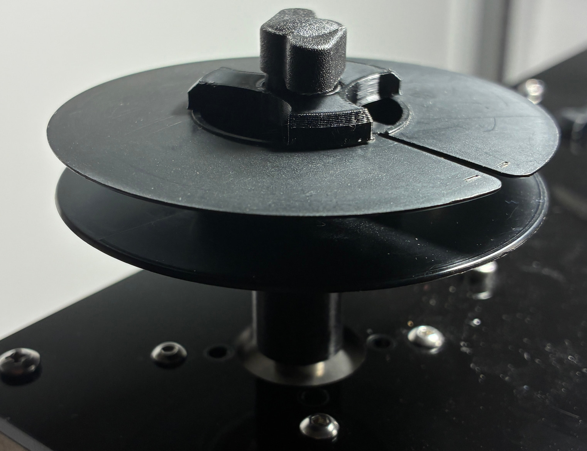
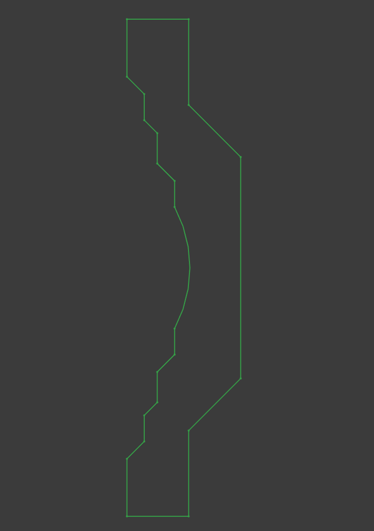
The smaller diameter guide rollers were also increased to a 14mm diameter, and reprinted to have the same material and groove shape. These were printed solid, since there is not much space to hollow them out, and these -according to the slicer- are just about 2 grams each.

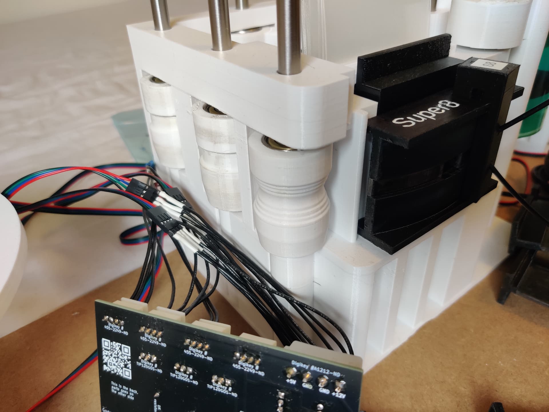
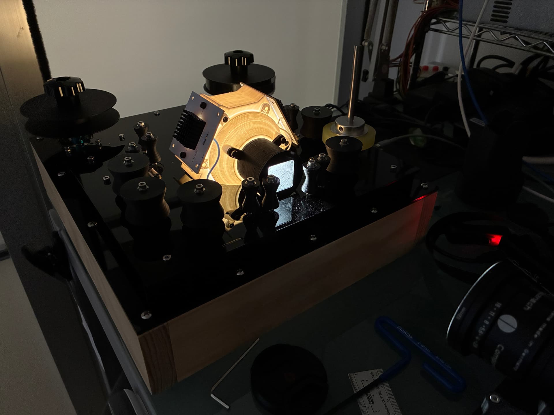
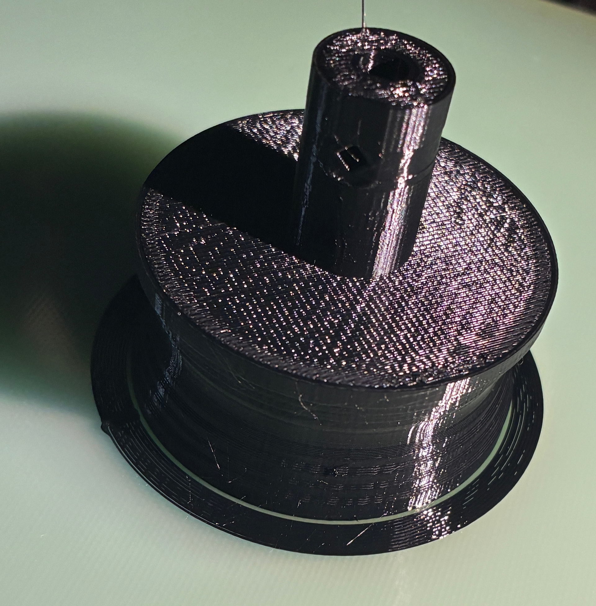
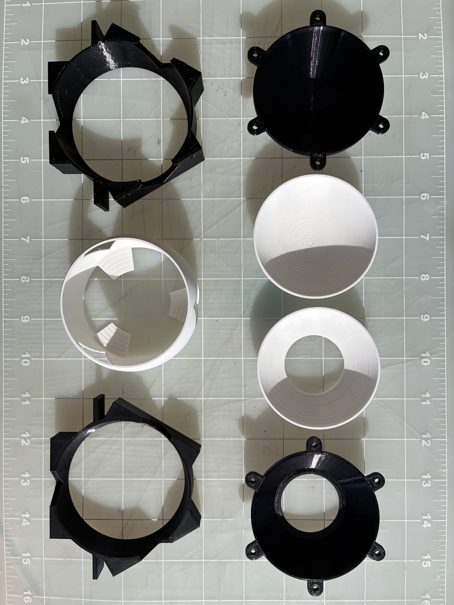
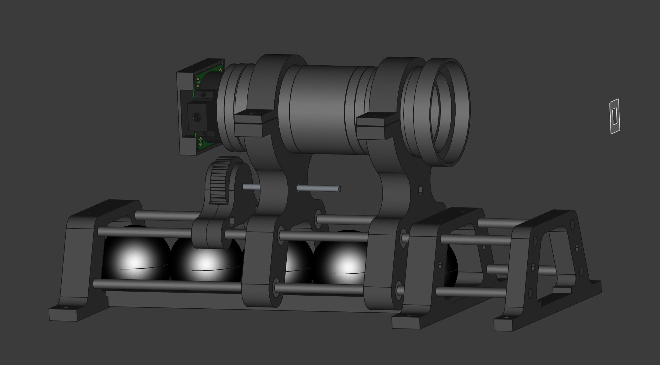
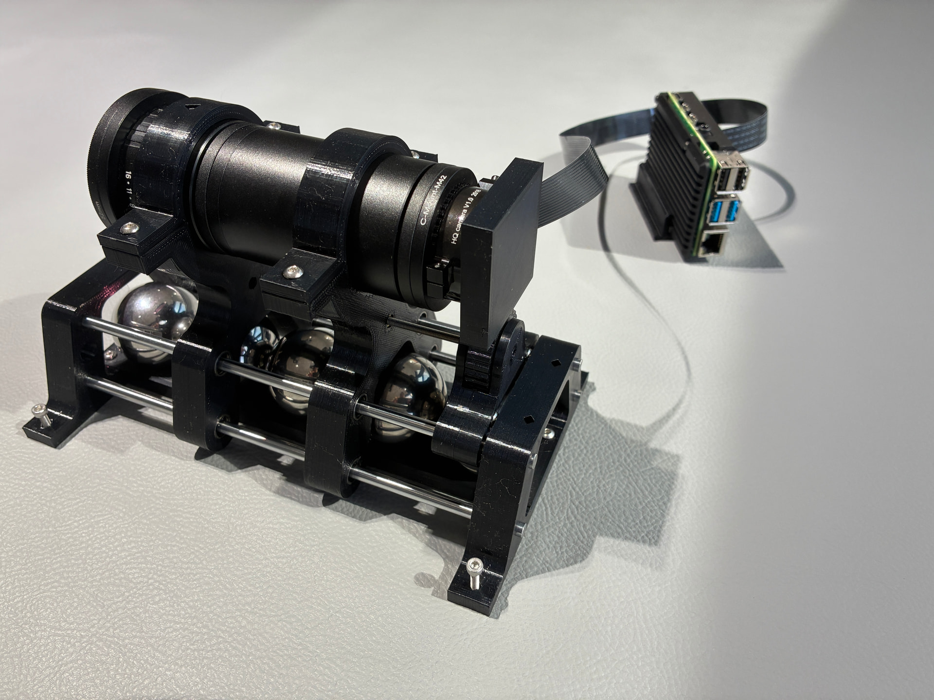
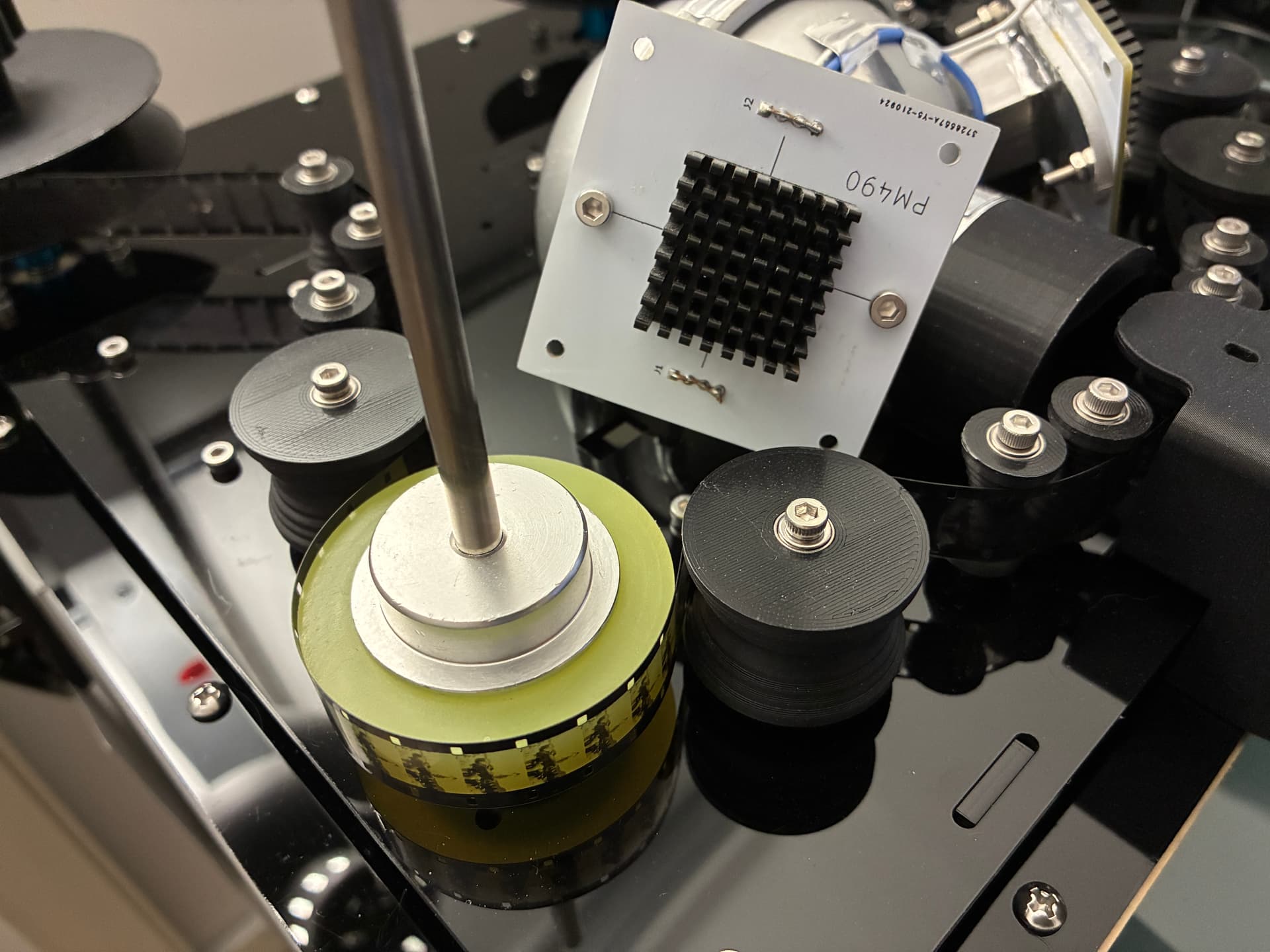
Picture of the new guide rollers (with 16mm film loaded).

New Stepper Curves
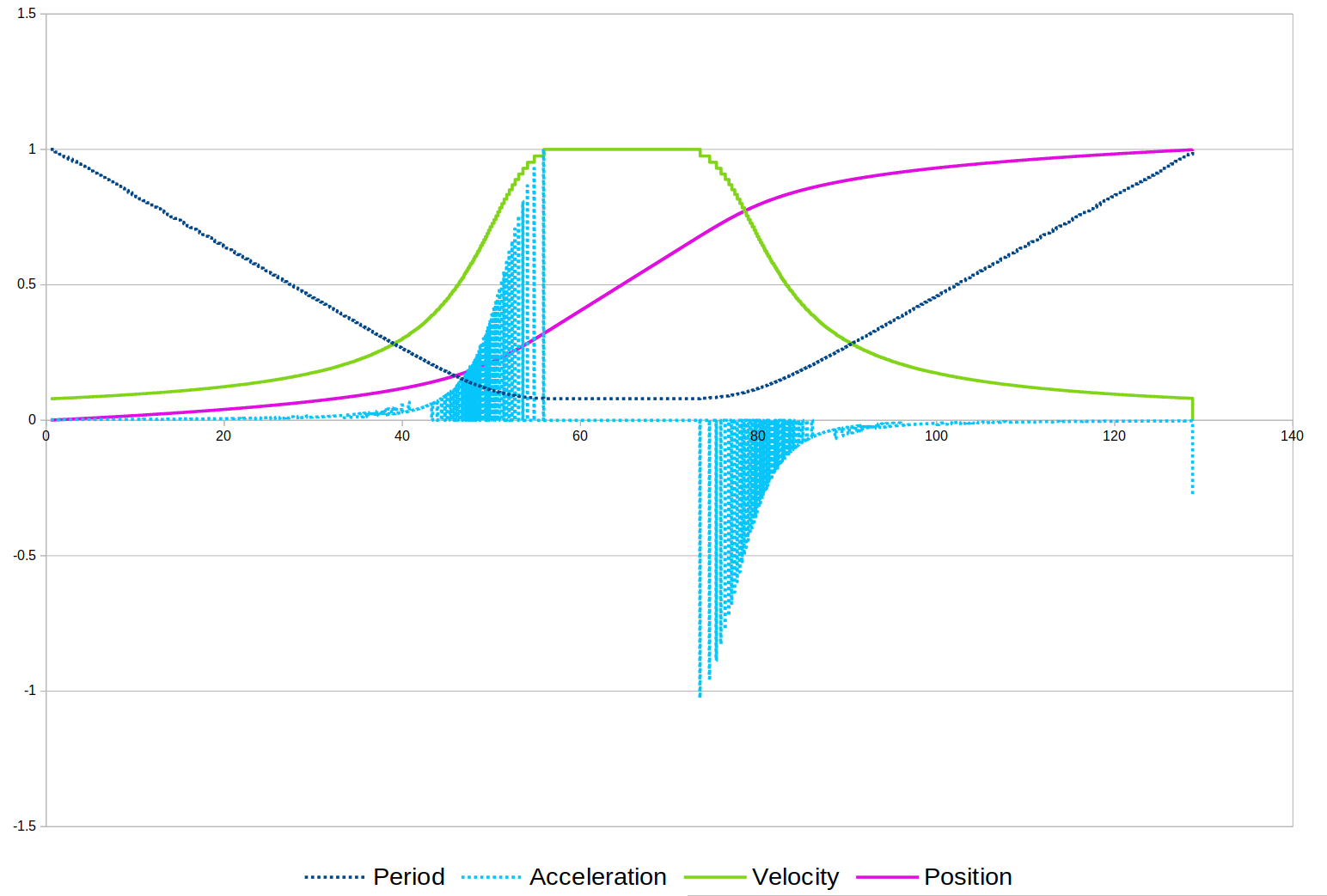
I had been using linear stepper speed control resulting in a trapezoid velocity profile for accelerating/decelerating the capstan stepper. In an effort to smooth the trapezoid, I tried using a velocity sigmoid shape, and the results were excellent, reducing the total time to move one frame by half, and slightly improving on the film movement. The sigmoid table is calculated for the number of steps required for 8mm. For 16mm the top is extended, using a single table for both.

F-Code (Film Code)
Finished coding the necessary commands for a minimum viable product in the PICO firmware. Still have a bit of cleanup to do on the code… but that is an endless task.

Next steps
It has been a long time to get the transport to this stage, but I am certainly pleased with the results. That is not to say that is perfect, far from it, but the cost/benefit is worth it.

From here…

  • RPi frame detection improvements.
  • A bit more PICO code cleaning and testing.
  • RPi user interface.
  • Testing special use captures (stacking and separating channel exposures).
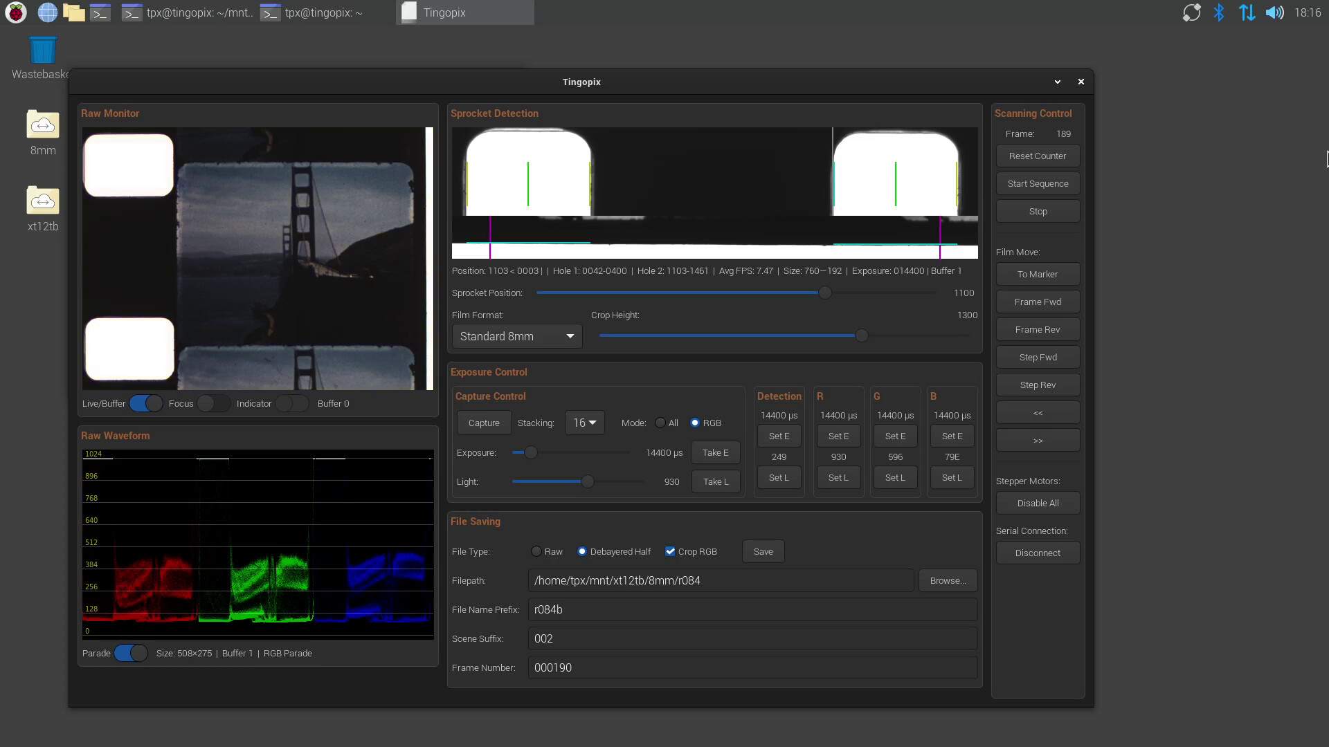
Tingopix
I will also begin to open-source-share parts of the scanner -time willing- and will do so in no particular order. It will be shared with the name Tingopix. Meaning: Tingo latin verb: to color, dye, tinge, or stain… pixels.
If anyone is interested in any section, please let me know and I will make an effort to prioritize it.

5 Likes

Thank you sharing the progress, and for offering to open source the parts.
I would very much like re-use your rollers, and therefore I would appreciate if you could share the model of the roller. Currently I’m building the Gugusse scanner, with some minor modifications to his models, but that scanner requires changing both rollers and gate for each format.

Thank you for the kind comments @ChrisCph

Gladdly. Here it is. The repository includes a pdf with an exploding view illustrating how the rollers are assembled.

3 Likes

Thank you Pablo. Really appreciate you sharing these.
When time becomes available, I’ll see if I can modify the large roller to fit my larger 608ZZ bearings.

You are welcome.

Are you building 35/16/8 or only 16/8? The rollers I shared are only 16/8

Edit: I looked at Denis Carl’s new the Gugusse compact, and see that coincidentally what the project references as flywheels are 32mm diameter, and uses the 8mm shaft. So I think what you are trying to do is make a flywheel for both 8 and 16. Not sure of the particulars of the rest of the design, and if there is an issue with having different diameters on the 8mm and 16mm path. But the part looks doable.

Bad news… the gugusse compact flywheels have a unique shape, and larger shaft. Modifying the one I posted may not be easy.

Good news… modifying the profile is not so hard. I made you one to match the form factor for the gugusse compact.


Now… what I know:

  • It should print well without supports
  • It will be lighter (with 100% infill, the standard flywheel requires close to 30grams, the hollowed 8/16 with 100% infill takes 19grams).
  • There should be no difference with 8mm film (The 8mm groove matches the diameter of the original compact flywheel).

What I do not know:
The 16mm new part -by design- has a slightly larger diameter, compared to the standard 16. I do not know if this will have any impact on the scanner inner workings or performance. I do not know enough about his design, did not see any red flags.

Here is the link (same as above), part number TPX-25-10002-A.
If/when you get your project running, and confirm the shape is good, please let me know to update the drawing removing the “experimental component for testing” warning.

Hope it works!

1 Like

Thank you Pablo. Again much appreciated.

The Gugusse scanner supports 8/16/35mm, but where the rollers have to be changed for each format (including the gate).
Currently my needs are only family 8, S8 and 16 mm films, so your roller design should cover that. I’ll see if I get the time in the weekend to print one, and I will post a comparison to the already printed rollers (can’t show it in action, as I’m still completing the camera control)

Best regards
Chris

1 Like

I managed to print your version for the Gugusse scanner, and it does the work splendidly.

Here’s a video of the roller: https://youtu.be/ZLNy0ob4Yh4
and some screenshots of it, side-by-side with the original gugusse roller (yours was printed with the 0.1mm layer height and for some reason caused my printer to detect a lot of crashes which can be seen as gaps in both the video og photo, whereas the gugusse was printed with 0.2 mm and has no gaps. This has nothing to do with your design, but rather my printer not being good at handling 0.1mm. Both are printed in PETG to avoid any shrinkage):

And in place in the scanner:


I assume you took the bearing measures from the Gugusse rollers, as it is a very loose fit for the bearings, which was true for the gugusse rollers as well, but a bit of hot glue solves that :slight_smile:

Once again, thank you so much for sharing your design. I will swap all the rollers in the scanner to your design!

I think you actually posted a link to the Gugusse somewhere here, which led me down that way, but maybe you would like to share your design in the Facebook group: Redirecting... for others to benefit from your hard work. I haven’t tested your roller with film or scanning yet, as I’m still modding the design a bit.

Best regards
Chris

1 Like

Hi Chris, thank you for sharing the results.

I also print at 0.2mm layers, that should work well if it is less problems for your printer. The ones I printed for my scanner were printed in PLA, and the material was not a problem. The printer I have is an old Ender 3 modified with direct struder (and other mods). I had better results with Orca Slicer than with other slicers.

Yes, kept the inner diameter for the bearings the same as the gugusse part (22.4 mm). I thought it was a bit loose to the specs, but without the part on hand, just used the same. By the way, there is a difference -as you probably noticed- in the bearing pit shape: gugusse part has a flat seat for the bearing, this one is at a 45 degree angle, to facilitate printing without supports. So it may be best to make it tighter.

I did a quick revision, changing the bearing hole outer (top/bottom) diameter to 22.2mm, and the inner to 22.12mm. That should make it tighter, without being too hard to slide in. Let me know if still loose.

Look for TPX2510002B_for_ denis_carl_gugusse_compact_8_16.3mf in the same repository.

Glad the part worked for you.

1 Like

I’ll try printing the new during the week, when I get the time, and will give you some feedback on the new bearing dimensions.
I wanted to try printing yours with 0.1mm layer height to get more precise dimensions, but the next print will be with 0.2mm to avoid the printer detecting crashes.

Thank you!

A bit of side tracking… this design iteration (Snailscan 2) started two years ago (top post) with building and testing an integrating sphere, made of aluminum baking pans (with some cutting for the ports), some short square aluminum tubes, some laser-cut flanges, and J&B weld. In the spirit of making the project easy to reproduce/assemble, this sphere design would not be a simple task. Incidentally, the LED PCBs used in the aluminum sphere were designed to sandwich an oversize ping-pong ball… and these are not the best form factor.

New 3D Printed Sphere Option
Before I make a new LED PCB, which I hope would also include other LEDs for testing, I figured it may be appropriate to design a 3D printed sphere. But not only is my know-how of 3D printing new and limited, but the printer I have access to (Elder Ender 3) has limited capabilities too. Unfortunately, printing something in the shape of a sphere directly would no doubt require many slicer supports for the primary shape, which leads to a rough surfaces.

After lots of considerations, the best alternative -that I could come up- was to split the sphere in 3. A center hub for the LED boards, with front and back covers. The inside of the covers is spherical, while the outside is a truncated cone at a 45 degree angle… so the Elder Ender would be happy to print these with slicing supports needed only for the D holes for the screws.

Ideally, the LED PCBs should be farther to the sphere surface to avoid any direct light from the LED to escape through the port (as it is on the aluminum sphere). But to make the light ports at the 90 degrees point, I had to limit the distance and incorporated some baffles to avoid the direct light. To make up for the truncated cone, the sphere is also 80mm (vs 100mm of the aluminum pans). Keep in mind that -for now- this is being fit on the same cutout as the previous sphere.

I intent to print on white mate PLA for testing (output port in black)… before the coat of barium sulphate, to make it better (and quantify the difference).

Work in progress, but it looks promising… and still using the same LED PCBs.

1 Like

Typically white filaments are slightly abrasive. Since you will be coating it anyway, I’m not sure there is an advantage. Also, consider the orientation in the slicer. If you orient it with the concave surface (inside of the sphere) facing up, all your supports will be on the outside, where it should not impact the interior surface. If you are going for a smooth surface, use Bondo, or other filler and fine sanding should get you to the surface finish you want.

1 Like

Aluminum Barium Sulphate Coated vs 3D Printed Matte PLA

Would like to share the results after testing the above model for 3D Printed. First a summary of the differences:
Aluminum Sphere

  • 100 mm surface diameter.
  • Coated with barium sulphate.
  • LED boards are slightly forward to the sphere with a narrow square tube for separation.
  • No baffles needed.

3D Model/Printed Sphere

  • 80 mm surface diameter.
  • Printed with white PLA mate (eSun ePLA white mate).
  • LED Boards are 90 degree to the output port, closer to the surface.
  • Baffles to avoid direct emission from the LEDs to the output port.

Capture Setup
Both spheres were tested with the same set of three LED PCBs. Each PCB uses 4 white LEDs, capture at approximate 50% power.
The HQ used has the IR/UV filter removed, and an external filter is used.
The software takes a raw capture (not a DNG), the result is binned into a 16-bit TIFF, “ExposureTime”:4800.
Both captures were done with the same Rpi HQ exposure settings, with a Schneider-Kreuznach f2.8 50mm lens at f11. Camera distance/focus were setup for 16mm full frame capture.

Results - Aluminum Sphere (Barium Sulphate Coated)


Results - 3D Printed (ePLA Mate at 0.2mm layers, unsanded/uncoated)


Summary
The surface plot and waveform output for both spheres is flat. The 3D printed sphere, while unsanded an uncoated, provides significantly more output light (higher channel levels). This is consistent with the larger ports, closer location to the sphere surface, and smaller sphere diameter.

This experiment demonstrates that the 3D design, printing material, and printing quality (even with an Elder Ender 3) provides equivalent results without the considerable time/effort of a coated surface sphere. Certainly, if the 3D printed design is improved by coating the print with barium sulphate, it may improve the sphere output. Keep in mind that a coated surface should provide a more even spectrum response.

3 Likes

I’ve been curious about the obvious glow of the 3D printed parts using white filament. Would there be any benefit (like additional light output) if the printed sphere were wrapped in aluminum foil? It would seem that this would reflect the “wasted” light back in and boost the output. Just a thought from the meanderings of my brain!

Thanks for the detailed analysis.

Thanks @junker, That is an interesting thought.

What I see (it can be seen in the picture) is that with this filament type (PLA matte) the light that bleads out is shifted to the yelow/redish. Assuming the aluminum does the work, the light reflected back would be filtered twice (on the way out, and on the way back in) and may shift the color light a bit.

Now with more translucid filaments like PETG, your suggestion may have better results. Haven’t done much with PETG, starting to use it to make some parts for the scanner.

The same way the light bleads out, if there is a light hitting the back of the sphere it would bleed in. With PLA matte, I can see it a small bias of the HQ black levels. To avoid it, I was considering printing a back cover in black, but haven’t done it. One has to actually point a lamp to it to make a difference, which is presently not a normal condition.

1 Like

Time for a new year progress update on SnailScan2 (AKA Tingopix).

The Goal: A low-cost, repeatable DIY scanner for 8mm and 16mm film, utilizing the Raspberry Pi HQ camera. No projector parts, just off-the-shelf components and 3D prints.
The Reality: High color quality, very low budget, but slower speeds.


Updated Parts: The All-Printed Path

With the newly updated parts, every film path component is now 3D printed. This simplifies the build significantly and uses fewer third-party parts.

Friction Capstan

The design has been using a friction capstan (no pinch roller). The silicone encoder previously used had significant runout (eccentricity) issues, which contributed to film position errors.

  • New Design: A new 3D printed version (PETG) that installs directly on the stepper axle was designed.
  • Benefit: Significant improvements on runout, and it eliminates the source for the parts (axle, coupler, and encoder).

Supply and Pickup Reel Mounts

The reel mounts previously used an 8mm threaded axle, with couplers to go from 8mm to the stepper axle.

  • New Design: A new 3D printed version was designed to simplify the reel mount. It uses a self-tapping thread insert (8mm to 4mm).
  • Benefit: This new setup is lighter, and the adapters for 8mm, Super 8, and 16mm reels provide a better fit.


Updated Parts: A covered Shere

  • Dark-mode Sphere To reduce glare from the translucid white PLA, the sphere was redesigned into an external shell (printed in black PETG) and an internal reflector with baffles (printed in white PLA Matte, same as the previous one). The center core is divided to keep the sphere to three sections.


PICO Controller & Film Code

I have completed the command-set to run the scanner, including full control of the micro-stepping settings for each stepper, and a command-set for separate control of each stepper if/when needed.

  • Sigmoid Advance: A single film advance command coordinates all three steppers. The capstan advances the commanded number of steps using a sigmoid curve (see previous update), while maintaining tension with the supply and pickup steppers.
  • LED Control: Intensity settings can be controlled as 16-bit linear (direct DAC value), 12-bit exponential value, or percentage.

Raspberry Pi Control GUI

This project had a long aspirational wish list accumulated over years. The list included:

  • Interface responsive enough to be workable via VNC.
  • Full resolution raw processing.
  • Real-time sprocket hole detection and capture preview.
  • Real-time waveform (from raw full-resolution capture values) with parade mode.
  • Easy selection between film format parameters from GUI.
  • Stacking (averaging multiple captures) for each channel separately or all channels simultaneously.
  • Capture image stabilization from sprocket hole edge and film edge.

GUI Toolkit: GTK4

The previous GUI framework was based on Tkinter, and chances of getting the wishlist done with an RPi4 were near zero. Also, Raspberry OS (Bookworm) updated the display server to Wayland.
The Solution: GIMP Tool Kit (GTK4). It provided the best combination of performance while staying open source.

Multicore Framework: “Everything Everywhere All At Once”

The RPi4 is a challenge for data-intensive apps, but it is an ideal test platform to optimize code performance. The new software was rewritten from scratch using a modular multiprocessor setup and shared memory manager.

The simplified processing pipeline:

  1. Libcamera Raw Capture → Area of Interest (blue only) debayering → Sprocket Detection
  2. In parallel: Debayer Preview (RGB from full res raw to 1/8 size) → Waveform
  3. In parallel: GUI
  4. In parallel: Controller → USB communication (Transport/Light)
  5. On Request: File Saver → Full Res Raw (Bayered) OR Half Res RGB (Binned)

“Out of the Blue”: Sprocket Detection

The system figures out where the film is by analyzing a 384×1520 pixel slice of the blue channel.

  • Vertical: The detector creates a vertical intensity profile. Sprocket holes show up as bright peaks. Once the peak is found, edge detection kicks in (85% brightness threshold) to nail down the exact top and bottom of the hole.
  • Horizontal: The same threshold-based approach is used horizontally to locate the film’s right edge. This is crucial for the Super-8 wobbling sprocket and electronically compensates for film shift without a physical gate.

File Formats & Capture Strategy

The Compromise (Speed/Space)

VNG debayering is great but computationally expensive.

  • Strategy: Save half-resolution debayered images (stride-2 binning down to 1520×2032, with black level correction and CCM applied). This delivers excellent color at reasonable file sizes for 8mm film, with options for stabilization and cropping applied.

The Raw “Trick” (Max Quality)

For full-resolution work, the system saves the Raw Bayer data (3040×4064) as a TIFF.

  • The Trick: Sprocket detection values (vertical/horizontal position, markers, crop height) are embedded into the last column of pixels in the raw file.
  • Benefit: This defers the heavy VNG debayering to post-processing while keeping the precise sprocket detection data that was captured during the scan.

Stacking and Multi-Channel Options

Two capture modes are offered to handle different film conditions:

  1. “All Channels” Mode: Captures all three color channels simultaneously. Simple and faster.
    GUI: All Channels - One Capture (16mm)
  2. “RGB” Mode: Captures each color channel separately and sequentially, using independent exposure and LED brightness. This allows compensation for fading while maintaining wide-band illumination.
    GUI: RGB Separately - 1 Capture = 12 bit depth (Super8)

Both modes support Frame Stacking (1 to 16 captures). Stacking 16 frames of 12-bit data delivers a full 16-bit image, reducing noise and extending dynamic range.
GUI: RGB separately - 16 captures = 16 bit depth (Standard 8mm)


Retrospective & Future

It is interesting how the landscape has changed. Just this year, Black Magic Design launched a separate Cintel dedicated to 8/16mm, and CUIMAGING is launching one as well. Somehow, a low-budget DIY scanner seems less out of sync today than a couple of years back.

In the trade-off of Quality-Speed-Budget, this scanner fits my priorities: high color quality images with a very low budget. An order of magnitude lower in cost… and higher in time.

Future Design Improvements:

  • Software: Optimize RGB camera/light changes to improve capture time; PICO code cleanup; Fine-tuning film movements.
  • Hardware: Replace laser-cut stepper mounts with 3D printed versions.

From October 2022 and the “time-of-flight” failure to today, the pending part of the goal is repeatability.

That is essentially: Tingopix.
Super 8 Test Capture (The tank actual color was teal)

4 Likes

16mm Test Capture

1 Like

Despite that the source material is far from optimal due to wear and some overexposure the scan is amazing! If I could build a scanner that could even come close to that I’d be very happy.

1 Like

Winter Sprint

Focus & Mount

The project has gone through a few mounts to support the HQ sensor, the Schneider, and the tube in-between. But a reliable mount and a good focus were missing… here the previous one.

It is no secret for anyone who has worked with 8mm film, that focus is critical, and sadly that became the weakest link in the workflow…

+ Motion Rods + Steel Balls

Steel balls used on the prior mount provided great results at improving stability, so the goal was to keep these, and add fine focus control.
This setup uses hardened steel rods and linear ball bearings mount the sensor-lens assembly. The focus knob was built using a 60mm M3 screw. The mount is illustrated with the length needed for 16mm. While the longer 250mm rods arrive, the shorter version is sufficient for 8mm distance.


The end profile bases transfer the weight of the steel balls, while keeping the sensor-lens light for smooth sliding/focusing.

Life Imitates CAD

All the components were printed in PETG, with tolerances tight enough to keep the rods and bearings in place.
The focus knob mount does not slide freely, only the lens-sensor support do. The know assembly is held by friction to the top-rods and may be manually displaced with slight pressure. The end bases have M3 Feet to trim the sensor-lens assembly elevation. The frame is aligned by rotating the sensor before tightening the top clamps.


Running on Trixie

Have been doing improvements to the Raspberry Pi GUI/Capture software, including some timing optimization on the stacking captures and color-channel light changes. Certainly, more can be done on another iteration. Also took the opportunity to move to Trixie, and fortunately there was only some minor CSS adjustments on GTK4.

Updated Picture & Screen

Here is a current picture of the project, with the black-sphere, the new sensor-lens mount, and using a printed pickup plate.


And screenshot of the RPi software on Trixie.

3 Likes

Scanning 16mm

Camera Longer Rods for 16mm

Full Sensor Resolution Scanning for 16mm

I purchased a 400ft reel, and it came with a bit of single perforation 16mm film (camera original). The content looks like a handheld test for film/development, so I used it to test the full 16mm processing.

Captured at 15bit (average of 8 images) and saved as TIFF 16bit with the embedded sprocket and film edge data. Post-scanning VNG debayering & stabilization cropping using the sprocket embedded info. Then crop the edges and resize to presentation format. The output is encoded to hevc 12bit depth and uploaded to Youtube.

Here the film, it repeats 3 times showing each step.

1 Like