Hi @PM490 - actually, your comment about optical mouse sensors prompted me to do a very basic test of this idea. I simply pulled a piece of scrap film back and forth under my computer mouse, like here:
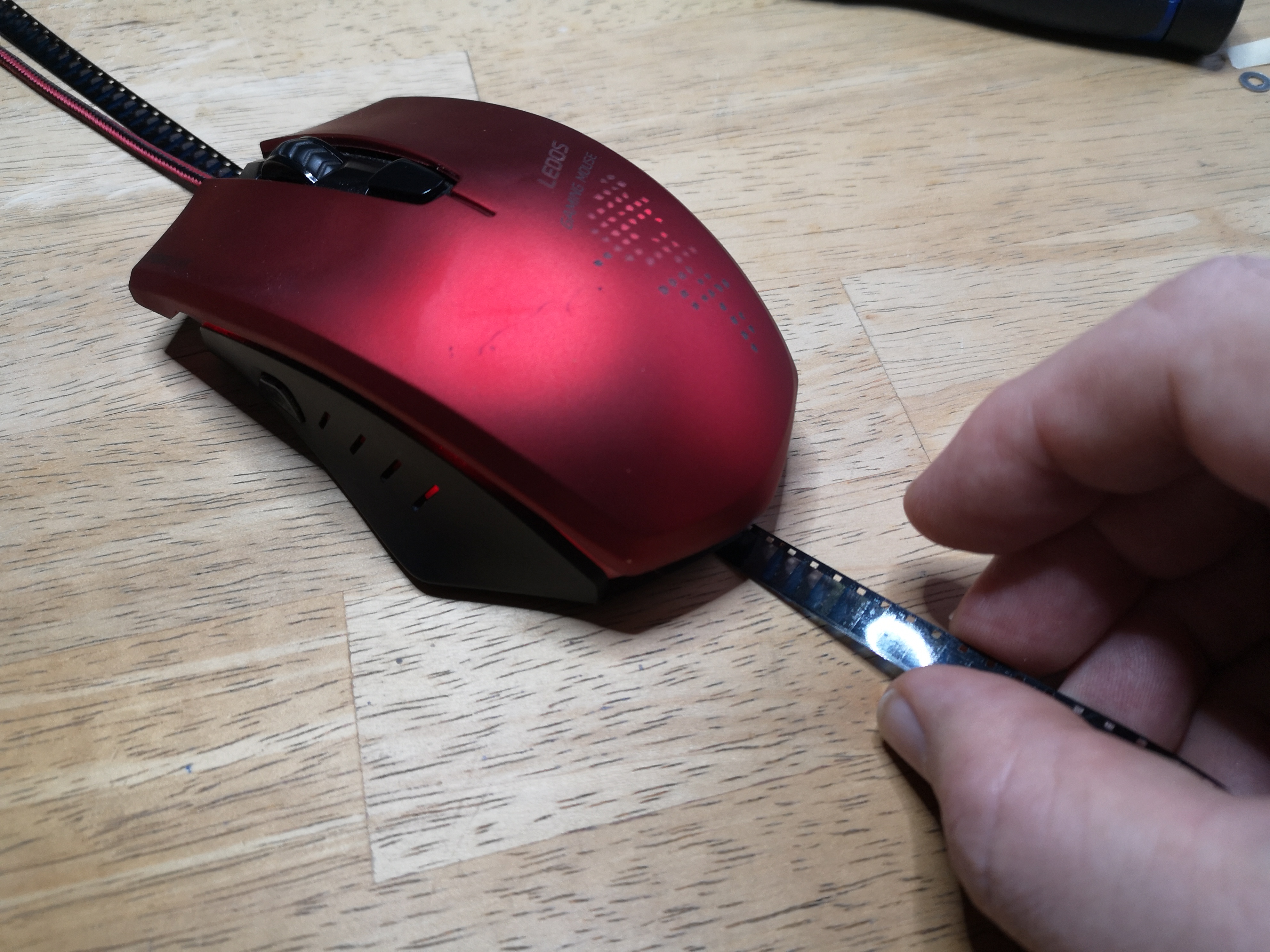
… and observed what happened to the cursor on the computer screen. Turns out that I see the mouse moving corresponding to the movements of the film. It seems that the sensor is less precise when it’s looking at the smooth surface of the film stock, compared with using the emulsion side.
Given that the actual mouse sensor hovers a few millimeters above the surface, and that there are interfaces available between old mouse sensors and the Arduino-family, one could imagine utilzing something like that as an optical flow sensor. At least there is plenty of headroom for the sensor (it would hover a few millimeters above the film surface), and it seems to generate a useful signal. The advantage of using an optical mouse sensor would also be that all the realtime computations and other design challenges are already taken care of by a mass-market product.
Actually, I think placing for illumination purposes a secondary LED opposite of the sensor-film-stack, in order to illuminate the film from below, could improve the tracking by the mouse sensor. The little camera in the sensor needs some structure to lock onto for tracking, and especially very clear or very dark film parts might be a challenge.
In your setup, where the frame position will be primarily defined by the gate/claw-combination, I think one should get a fine signal for a camera trigger out of such a setup. There will possibly be a limit on the fps with such a sensor, no idea how to estimate or test this…
Here are some additional thoughts with respect to a setup which does not use a claw to position the frame (continous film motion - not your current use case). In such a setup the camera needs to be triggered just at the right point in time to catch a frame.
Any optical flow computation can be expected to drift away from reality over time (that’s my experience from working extensively with optical flow algorithms some years ago, in another life… ![]() ). Also, if you are using optical flow algorithms, you are not tracking the sprockets, but just the film itself. So you need to somehow generate a secondary signal in sync with the sprockets in order to trigger the flash and the camera at the appropriate time.
). Also, if you are using optical flow algorithms, you are not tracking the sprockets, but just the film itself. So you need to somehow generate a secondary signal in sync with the sprockets in order to trigger the flash and the camera at the appropriate time.
One possibility to handle that challenge and still rely mainly on an optical flow sensor for tracking would be to use directly the frame+sprocket as seen by the camera and do a fast enough sprocket detection on the current frame. Once the sprocket position is detected, you can use the optical flow signal to predict the sprocket position in following frames. Then, after some time, the sprocket detection algorithm is run again on the current frame to resync the estimate of the sprocket prediction by the optical flow algorithm. In this way, the computational load stays limited.
Such a scheme is actually similar to the approach I am using in my own film scanner - which is a slow beast compared to your goal. I scan only about 18 frames per minute (doing stop motion and taking several exposures of each frame). Due to mechanical deficiencies, the sprocket position tends to drift over time. Actually, it is moving up and down quite a bit.
So after each frame is taken by the camera, the current frame is analyzed and the number of the steps moving the film forward is adjusted to keep the frame more or less centered in the camera view. For the sprocket detection, I am using the algorithm described here which is computationally fast enough for that purpose.
This gives me a coarsly registered sequence of frames which I correct for in later processing steps, basically using by the same algorithm in the post processing pipeline again.
I think something similar might be feasible to combine with a predictor for the sprocket position based on an optical flow algorithm which is once in a while resynced with the actual sprocket position