Test Patterns Development

And exchange at the 4K camera purchase for Kinograph v2 testing sprung the idea of creating a test pattern using a high resolution photoplotter for the purpose of testing camera/lens/combination using a target quality higher than what is available from the 8/S8 film.
The majority of file to film options available are limited to digital graphics resolutions (about 3000 DPI). Given 8mm frame is about 5mm wide, that is not enough for meaningful measurements. The alternative is using photoplotter/photo tooling service like Fineline Imaging which provide photoplotting services with up to 50K DPI capabilities.
I am researching the options and plan to generate a gerber native pattern, probably using KiCad, which would serve for the purpose of testing and focusing at an 8mm gate.
Found this SMPTE reference which includes dimensions for other film sizes too.

Would like to exchange ideas on what others are using for similar purpose in an effort and also determine what is best to include in this test pattern (black and white film).

PS.Thank you at @cpixip for pointing available smpte test and also other available glass targets.
Thank you @robinojones for the suggestion to start this thread.

1 Like

Summary of 8mm and Super 8 film dimensions


Also in pdf

@PM490 - I am reposting here my own take on the dimensions of the Super-8 format for reference:

_Super 8 Format with Sound 3.pdf (93.6 KB)

My dimensions are slightly different than yours - will take some time to align.

I am pretty sure about some of the dimensions in my drawing, but a few ones are only good guesses, as no real information was available on the internet.

From what I remember, there are actually two different Super-8 dimensions (called short and long pitch film stock) and they are related to original film and film which was used for dupping the original film “emulsion onto emulsion” by a stacking original and dub onto each other. I think we both have drawn the original film dimensions, not the dubbing stock.

I have included in my drawing the positions of the magnetic stripes used with sound material. Not exactly sure about the placement, but the dimensions should be as specified.

Also, I discovered while creating the drawing of the specs that there is a slight shift between the camera frame (blue in my drawing) and the projector frame (red) - I am not really sure whether this is the case. In fact, it makes no sense to me and is probably an indication I got a few numbers slightly wrong. It’s been years ago since I looked into this, but it was the best approximation I could come up with by using public available data.

In any case, real Super-8 camera frames mostly exceed the specs (so you get more image area) and real projector frames are usually a little bit smaller than advertized (at least the ones I looked into).

1 Like

@cpixip thank you for sharing. I’ll take a look to reconcile, I did everything in inches and then converted to mm. The source data is the the SMPTE test patterns, also from this post, and also an image found at this post

1 Like

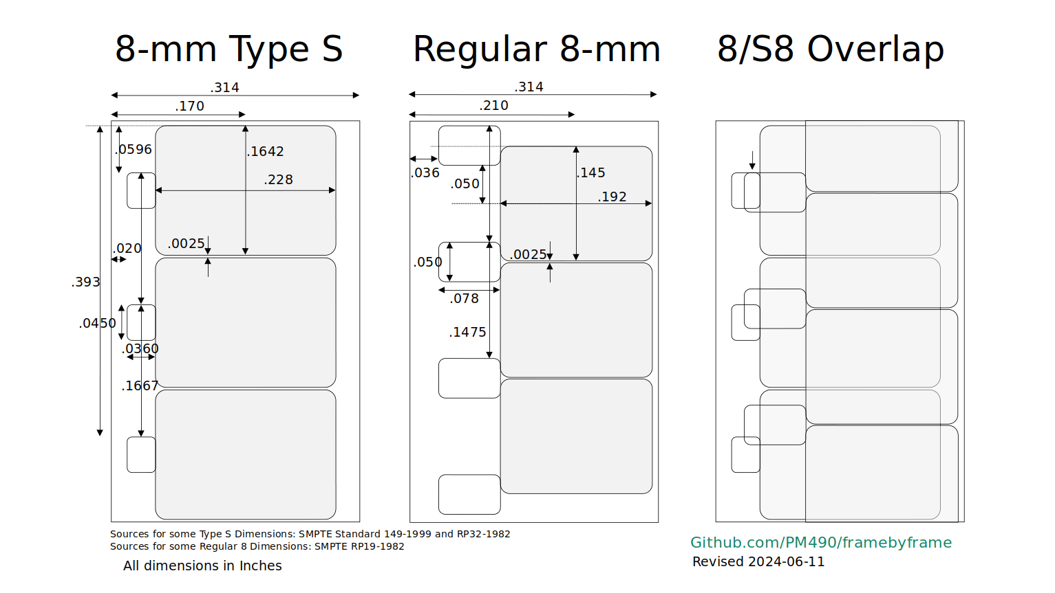
here’s an additional reference - with at least one typing error: the fillet sizes are 0.13 mm, not the 0.013 mm cited on that page. All other dimensions seem to be ok.

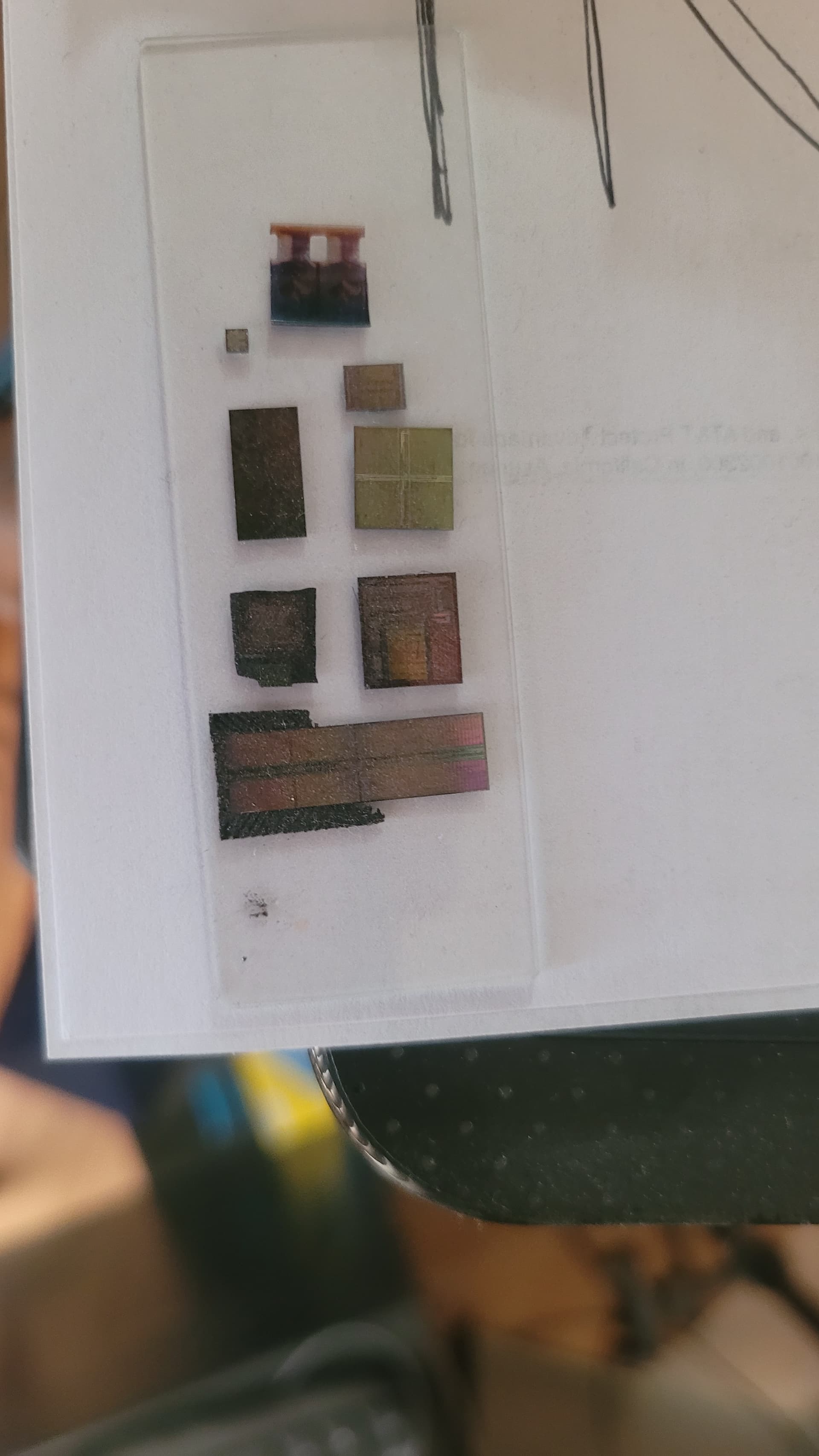
UPDATE: Actually, I was able to “sort of” reconstruct the way I arrived at the dimensions posted above in the drawing.

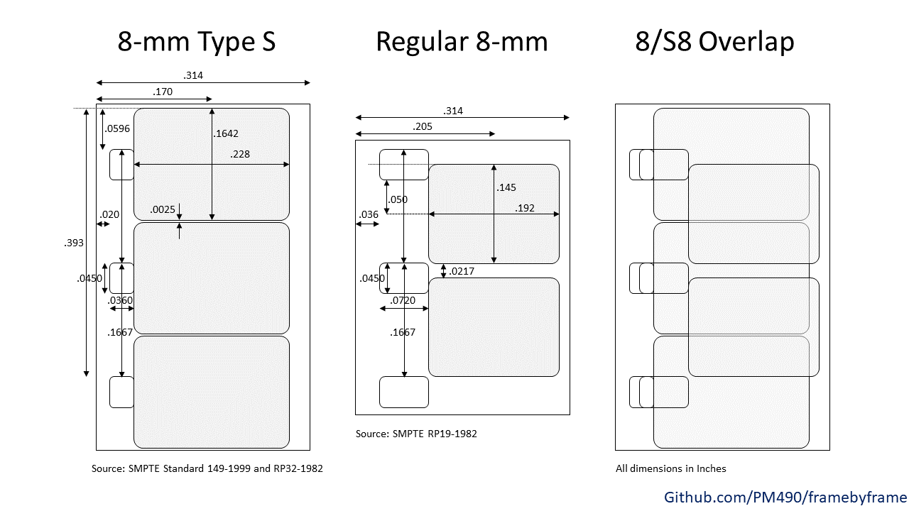
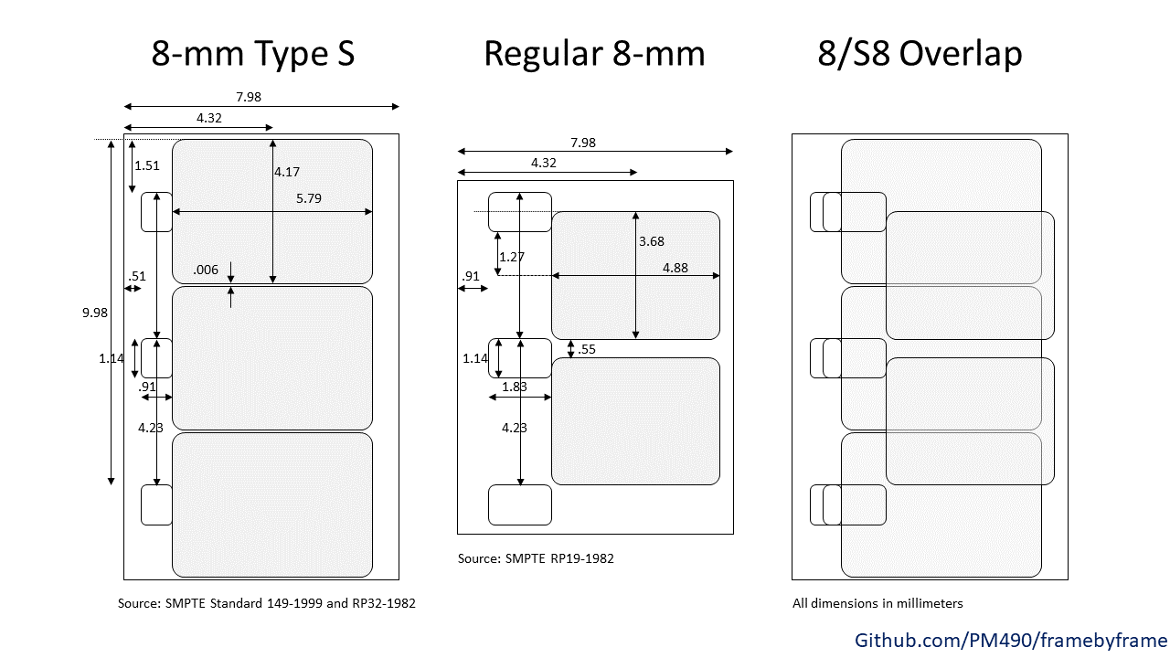
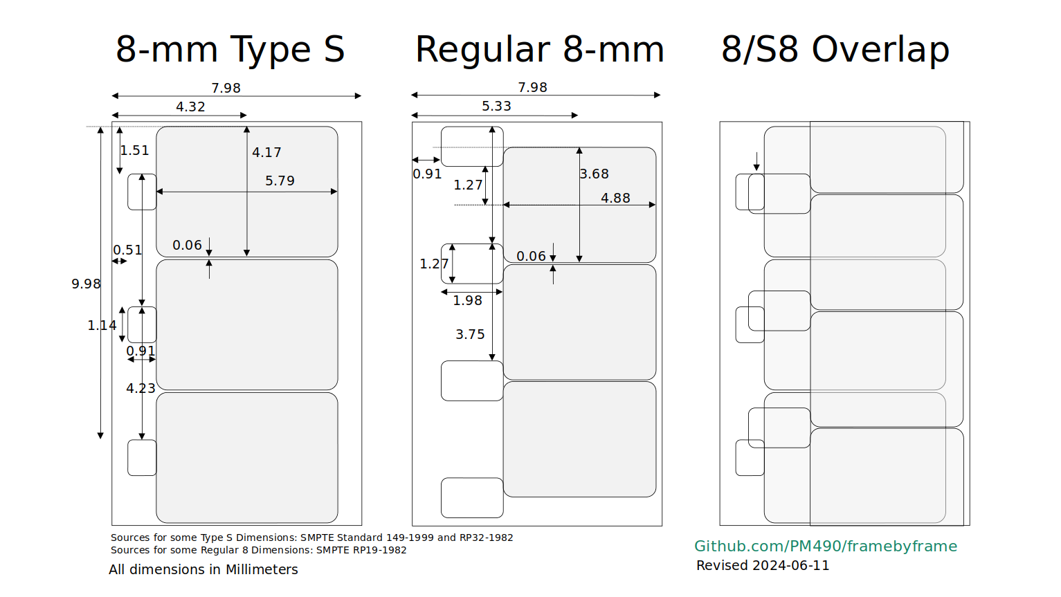
Basically, I searched the internet for information about the dimensions of the Super-8 format, but initially only found conflicting information. I than scanned a small slice of Super-8 footage and compared the information found on the internet with my scan. Only to discover that probably most drawings/dimensions I had found so far were at most good guesses. But: the reference in the first paragraph of this post stood out as perfectly matching the scan of my own footage. Also, it was in familiar SMPTE parlance. So I decided to use these dimensions as basis for my drawing.

With two exceptions: one dimension which I think is wrong is the fillet size, which is certainly closer to 0.13 mm in all of my film stock than to the one cited in the reference.

The other dimension which I think is probably only partially correct is the width of sound strip (balancing track) on sprocket holes’ side. The sound movies I measured (both commercial ones and my own ones, which were normal Super-8 footage coated in the early '80s with magnetic stripes after editing) had a width of at least 0.3 mm, not the 0.13 mm cited in the above linked reference.

I think the reason for this is the following: the balancing track was originally only thought to counteract the additional thickness of the real sound track on the other side of the film stock. Because companies used the same magnetic material for both the actual sound track and the balancing track, it was however possible to record onto that balancing track additional sound. Which soon some people did. “Duo”-Sound projectors appeared which were able to record and play back on both tracks. I think that was the time were the balancing track was specified to have a width of 0.13 mm. Realizing that the two audio channels might also be used as a stereo sound media, later in history “Stereo”-sound projectors appeared. I think this was the time the width of the balance track was increased to used nearly all the available width between the edge of the film and the sprocket holes. In this way, the sound quality of the channel, specifically the noise level, could be improved.

In fact, my own “Stereo”-sound projector delivered quite satisfying sound from both channels - there was barely a difference noticable (certainly not by the unexpecting audience).

So in summary, I think that my dimensioning of the Super-8 format gets quite close to the truth of the subject. Not 100% sure about the width and placement of the balance sound strip, but I think that varied anyway between different suppliers. Also, as already noted, basically no camera manufacturer kept the camera window to the specs. I even have seen cameras which exposed partially the area between the sprockets with image data. The same goes for most projection windows. They are typically a little bit smaller than what the specs state.

1 Like


This is what I use. A bunch of old silicon & a single frame of 8mm. The chips almost always have registration marks. I can compare with the original masks. Error checking is then far beyond optics. Then I switch over to peice of film.
I just wish I had a peice of old film showing a color chart.

2 Likes

Thanks for sharing the process.

@cpixip The fillet radius coincides in this and the regular 8/S8 comparison as .13 mm, which I did not specify (only specified the hole size).

Any discrepancies on the drawings I posted? I tried to stay with SMPTE since they actually produced the test film standards, which for the purpose of the Test Pattern Development is the safe bet.

well, so I was measuring/estimating the fillet size sort of correctly.

The basic difference between your drawing/dimensions and mine are the frame dimensions. Following this page, I arrived at two different window sizes for camera and projector, while you are only working with a single window size. Let’s compare (normal: your window dimensions/bold: my camera window/italics:my projector window):

  • Width: 5.79 mm / 5.690 mm / 5.460 mm
  • Height: 4.17 mm / 4.220 mm / 4.010 mm
  • Frame Separation: 0.006 mm / 0.014 mm / 0.224 mm

As manufacturers did borrow some creative freedom in the design of cameras and projectors, the differences probably do not matter.

Another unimportant difference between our drawings is that you worked with three digits precision, while I was using 4 digits. For example, the total width of a Super-8 film is given in your drawing as “7.98 mm”, whereas I used “7.976 mm”.

Other than that, I think the dimensions in our drawings agree with each other. From a practial point of view, they are identical.

1 Like

The frame dimensions I used are the camera aperture image in the SMPTE pattern specs. As you mentioned, cameras vary widely, so these are minimum frame size. The projected image is also available, but did not see the need to complicate.

All dimensions were taken from inches (mil) and then converted to mm rounding to two decimal digits.
Thanks for reviewing and comparing, we have a good starting point for the purpose of developing the test pattern.