Well, here are the details. As I already noted, what I am going to present are just preliminary results, and I have not yet thoroughly checked my approach for feasibility or correctness. Nevertheless, here’s a graph showing the color fidelity one can expect from a Raspberry Pi HQ camera with IMX477 sensor, viewing a standard color checker illuminated with light of varying correlated color temperature (cct):
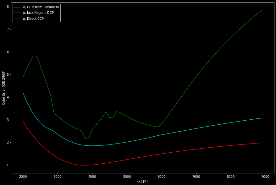
As you can see, the color error has a minima with all three curves (I will later explain these curves in detail) around 4000 K and goes up for warmer (lower cct) or cooler color temperatures (higher cct, less worse). A color error larger than one in the above diagram would be just barely noticeable in direct comparison.
These curves were not obtained by direct measurements, but by simulating actually a virtual light source shining on a virtual color checker and seen by a virtual camera sensor. The simulation is based on the spectral distribution of tungsten-type light sources, the spectral distributions of classical color checker patches as well as filter responses of the IMX477 sensor and the IR-blockfilter in the camera. It’s quite a complex piece of software and I haven’t tested it thoroughly (or even the feasibility of such an approach). So take the following discussion with a few grains of salt.
The green curve displays how close libcamera would actually come with it’s own processing pipeline. This processing is governed by the data in the tuning file, and I did not fully include all processing stages. Specifically, I did not include the ALSC (automatic lens shading correction) and gamma curve (rpi.contrast) modules in the simulation - both would make libcamera perform worse than the green curve in the above diagram.
The jaggedness of the green curve is actually due to the set of compromise color matrices (ccm) in the tuning file. It seems that very different light sources were used in obtaining the set of calibration images the ccms in the tuning file are calculated from, possibly mixing fluorescent and not so perfect LED-based sources with Tungsten or other lamps. Well, just a guess. But the sequence of ccms in the tuning file does not vary smoothly with cct, and it shows up in the color error as well.
Note that if you would base your raw processing on the camera matrix embedded in the .DNG-file, you would end up with results similar to the green line in the above diagram. Otherwise, the JPG-images/preview-images are produced that way.
The cyan line in the above diagram displays the result when using the simplest DCP-input profile for the IMX477 sensor, created by Jack Hogan. The color error is less than the libcamera reference, and it varies much smoother with cct. If you look closely, there are still two tiny bumps in the curve - that’s were the two reference matrices of the DCP input profile are located, slightly below 3000 K for illuminant stdA and around 6000 K for illuminant D_65. In any case, according to the above diagram, you should get better results if you use Jack Hogan’s DCPs instead of the “camera matrix” in a raw converter.
In a film scanning application were the light source (and it’s cct) stays fixed (that excludes color-mixing LED setups with dedicated groups of LEDs for the primaries), it is possible to actually calculate an optimal ccm for the fixed situation (in terms of illumination). The result in terms of color error with such a direct, fixed matrix is displayed as the red curve above. Note that the optimization of the direct ccm is currently not optimized, I am still working on this part.
All the simulations used in the above diagram were obtained by using a tungsten-like illumination source (specifically, a “black-body radiator”). I am still in the process of enlarging my simulation to include arbitrary light sources (for example with the spectrum you displayed in your post). And of course, these simulations need to be verified whether they relate to reality, by actually taking calibration images with a real IMX477 sensor. So there is still work to do.
I must confess that these things are probably not really that important, as different film stock and even different reels of the same film stock show much stronger variations in color rendition than the color errors we are discussing here. To show you what we are talking about, here’s the actual color chart rendering of the simulations above, at a cct of 4800 K:
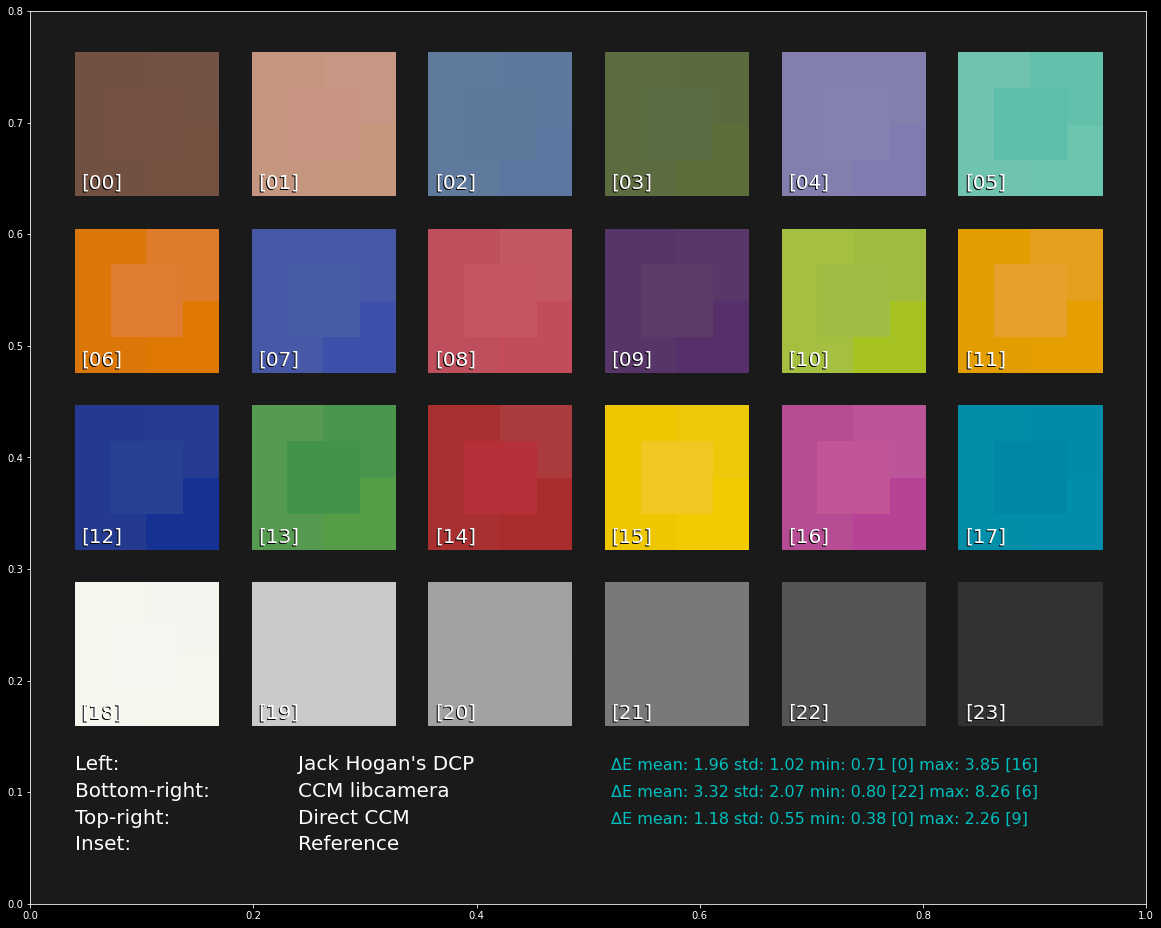
If you look closely, every patch features a central patch - that is actually the color each patch should have. Around each central patch, various other segments show the result obtained with the different processing options discussed. On the left side, Jack Hogan’s input DCPs were used, bottom-right the result of libcamera’s ccms are displayed and top-right the CCM calculated directly for the cct (“Direct”) is displayed.
Again - these color variations would not be noticeable if not viewed side-by-side, and they are definitely smaller than the color variations I see in different reels of color-reversal stock. So all of the above discussion is probably slightly academic…