The “Color Science Basics For Filmmakers” YouTube video just posted by @PM490 is EXCELLENT! I recommend it to anyone who is attempting to understand this thread and failing (me)…
Also, thanks to the titanic contributors here for the healthy debate on the true essence and constituents of what is being scanned vs our use and perception of that material.
2 Likes
Just for the record: that is not really an analogy, as audio is (and stays during filtering) a temporal signal, so it is and stays intrinsically multidimensional (lots of audio samples spaced at evenly distributed points in time). The reduction from a multichannel spectrum into a single number is different from that.
Well, somewhat corresponding, there have been similar developments in RGBW camera sensors, actually quite early (the link is from 2012). While some people see advantages in such an approach, I think one has not really seen a market breakthrough for these type of sensors. It might be an interesting thing to try out in terms of film scanning anyway. Especially since your idea, while based on similar filtering, uses a monochrome camera, so I expect the challenges/results to be somewhat different.
Thank you @cpixip, but I did not follow what you meant.
Granted light are particles also, but both are waves. Moreover, a single pixel sensor is sampling at evenly distributed points in time.
Thank you for the references to RGBW sensors.
Another considerations on the WBR or WGBR for the film scanning application is that using a monochrome sensor reduces the hardware cost dramatically, it is not subject to the bayer filters. It is however, more time and processing intensive.
Again, thanks for taking the time to exchange perspectives. At this moment I do not have the components to test, maybe after I get the W-Color sensor scanner working, will find some funds to get a monochrome sensor and do the WRB experiments.
1 Like
Found that there are some sensors using a similar approach to what I described above as a combination of WRB illuminant and a monochrome sensor. The color filter array for those is abbreviated as RCCB (or RCCB sensors).
This TI paper explains the use of Image Pipe for alternate formats as RCCB. (C = clear)
– just in case anybody is interested in more color science:
Follow the links in this list into the rabbit hole. ![]()
… and, adding another link here, a .pdf about “Cinematic Color”.
While we’re at it: here’s the first “SMPTE Essential Technology Concepts” webcast, by David Long, about color, contrast, and motion in cinema.

Very interesting discussion about what for me is the hardest part to pin down: the backlight. I have yet to find a good white LED with a reasonable flat spectrum. How flat is “flat enough” for you other guys?
I had the same thought as @dawsmart on the backlight, as using a car incandescent light as lightsource. Since we’re chasing a light source that is close to the spectrum of a projection bulb, it seems the simplest way to go. The obvious downside would be the heat production, but maybe it can be managed? Has anyone done any serious tests with spectral analysis, temperature and lumen production on small bulbs?
Also, how many lm does your setups have to make a good image in general?
I came across this sensor, it was mentioned in an Adafruit video, and it is an interesting tool for measurements of light quality.
Thought it would be of interest to you.
1 Like
![]()
![]() absolutely! In fact, I have one AS7341 sitting on my desk right now - the AS7341 features three sensor channels less than the sensor mentioned in Adafruit’s blog, but it is currently available as affordable break-out bord. Up to my knowledge, the new sensor’s breakout board is only available via ams.
absolutely! In fact, I have one AS7341 sitting on my desk right now - the AS7341 features three sensor channels less than the sensor mentioned in Adafruit’s blog, but it is currently available as affordable break-out bord. Up to my knowledge, the new sensor’s breakout board is only available via ams.
Both sensors need proper calibration in order to be used as a measuring device, very similar to the color calibration of cameras and sensors - therefore, I am currently refreshing my memory on color science. It’s been 20 years since I last worked in that field…
1 Like
Color Science, Cameras and the Backlight
I want to make a certain point about the backlight of a film scanner I think is important.
Diving again, after more than 20 years, into many things related to the way humans visually perceive their world, I am pretty sure now that there is one thing you should not use in the backlight of a film scanner: a mixture of narrow-band LEDs.
Rather, use the best white-light LED you can get. At least if you are scanning color reversal stock.
Why? Only a camera mimicing closely the way our human visual system works will “see” the colors of a color-reversal film similar to a human observer. In technical terms: the camera should mimic the “CIE 1931 2° standard observer”. As the name indicates, this standard observer was introduced in 1931 (on the basis of initially 17 observers) and has seen additions (like the 10° observer) and modifications over time - but the model and its associated color values (X, Y and Z) are still in use today.
A perfect camera (= one that sees the world as humans do) should produce for any given color patch values of X, Y and Z identical to the values the standard observer would “see”. Well, high-end cameras come close to this, but due to various technical reasons, they are not perfect and probably never will.
Now comes the important point: the filter response curves of humans which are somewhat hidden in the standard observer are broad and overlapping. And so do the filter curves of any high-end camera on the market.
The filters need to be broad and somewhat overlapping, because otherwise, the cameras would see occationally color differences where a human observer would not, for example. An extrem example in this regard are hyperspectral cameras, which see much more of a scene compared to any human being. Typically, these cameras use a set of very narrow filters across the full spectral range (or some other, equivalent construction).
However, to recap this again - if you want to record with a camera colors as similar as possible to the human visual system, you need three broadly tuned filters that you can transform to the X, Y and Z values of the standard observer. This transformation is actually happening in any software processing raw image files, as well as in any camera spitting out directly jpgs or the like.
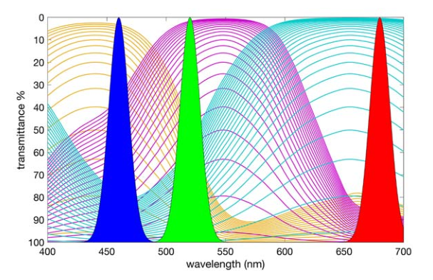
To illustrate how broad the filter curves are, here are the filter curves of the IMX477 sensor used in the Raspberry Pi HQ camera:
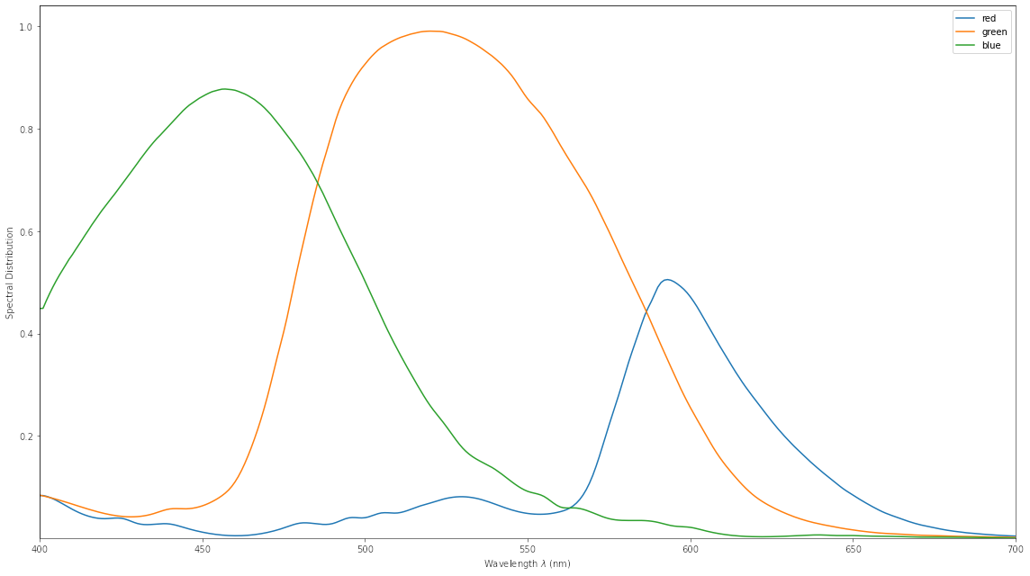
They show exactly what I was describing before: the filter curves of the sensor are broad and overlapping. In fact, any other camera shows similar curves - they need to.
Now, if we use as illumination source a combination of different narrow-band LEDs, we actually kill the performance of any camera! Why? Have a look at the following plot, which shows the spectral distribution of daylight around noon (D65), a light used in projectors (Kinoton 75p) and my current backlight setup utilizing three narrow-band LEDs operating at wavelengths 465 nm, 512 nm and 634 nm. All three light sources would produce the impression of being a “white” light when shining for example onto a gray card.
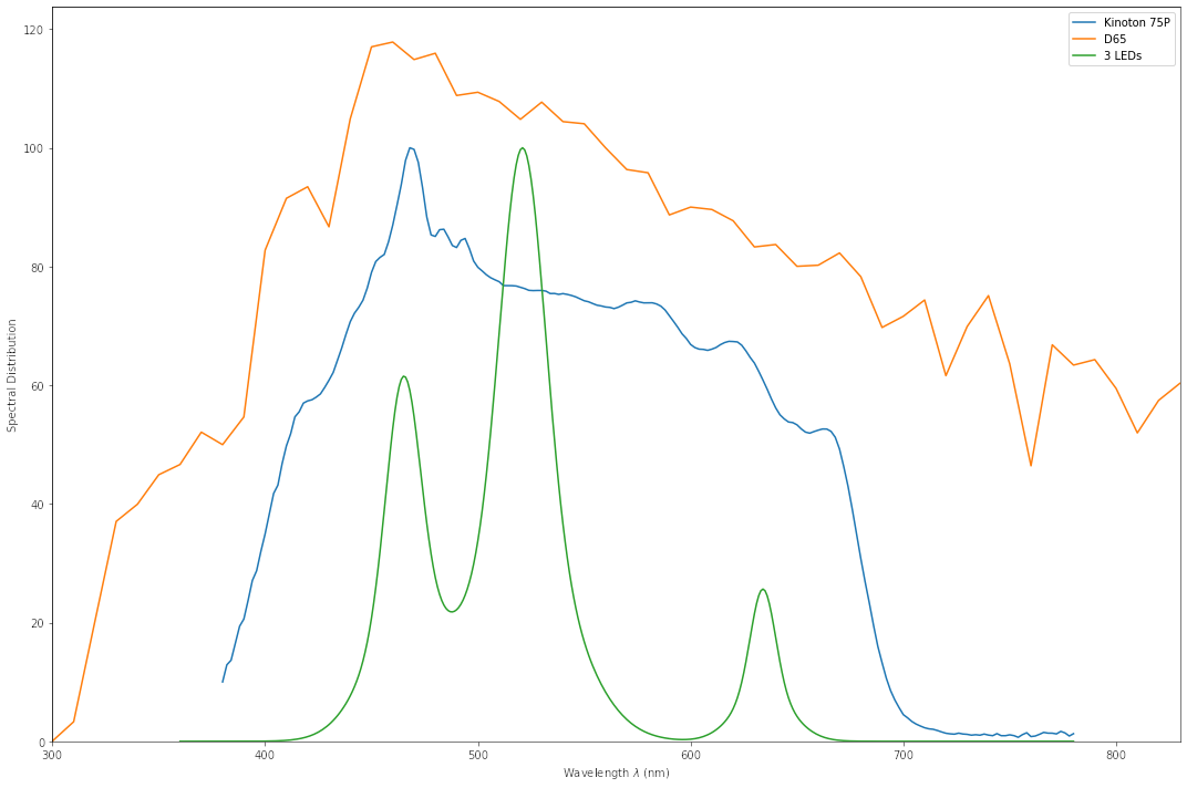
Now imagine for a moment having a film frame with a slight color variation in the dyes of the film, around 600 nm. When using daylight illumination or the projector light, this color variation will be noticable by any camera as well as human observers.
But: nothing will be noticed in the case of my narrow-band LED setup! This is because there is simply no light available at that specific wavelength to sample the variation. No camera, no human being will notice this color variation with my LED-source.
Note that the same issue also applies to scanners employing narrow-band filters in front of the camera. While these things are good at picking up detailed spectral information in a narrow band, they fail miserably when it comes to good color reproduction. And as there is no way whatsoever to recover the missing color information as there is no way out of this trap.
So, for a good color reproduction, you will need a light source with a broad spectrum, ideally very close to average daylight illumination.
In conclusion, do not use backlight produced by a set of narrow-band LEDs for scanning color reversal film - there is no chance of getting your film’s color right.
5 Likes
Negatives aren’t projected, they’re printed to positives which are then projected.
Exactly right. The tinting will cognitively disappear in a darkened cinema. You’ll only notice it if it’s sandwiched between scenes tinted normally (or differently) in which case the colour timing looks messy.
Absolutely true. That’s why I restricted my post to color-reversal film. I probably didn’t make that point very clear. Good that you pointed that out.
Having learned a little bit more about color science, I would actually drop my comment “stay close to an illumination spectrum similar to projection lamps”. From what I am seeing, it seems that the performance of camera sensors in terms of color fidelity drops with warmer light sources like a Tungsten 3200K. I still need to do some more research on this matter.
1 Like
True, for color negatives, and as mentioned by @cpixip his comments (and all charts I posted to illustrate) are for color reversal film. Although B&W negatives are also not projected, there is probably not an issue for those.
@filmkeeper, you bring up an interesting topic.
Given the findings for color reversal, what is the best approach to negatives?
If the offsetting of the light is done by adding a blue narrow band LED (a spike in the illuminant spectrum) which is the result of a white LED + Blue LED… that create similar issues for the sensor to what is being discussed.
I don’t have broad experience with negative for moving images, but from the experience with color photo negatives.
Negative to sensor challenges of dynamic range and signal to noise of the resulting inverted/corrected image are another subject. Although the blue LED improves the signal to noise for the blue channel in the sensor, it does so only on the narrow band of the LED. Blue rendition is improved, but only on the narrow band that the LED provides.
Intuitively, I would think it is better to use filter a notch filter to attenuate only the orange color band of the negative orange, instead of the practice of adding blue light.
Another intuitive alternative, but only applicable to stop-motion scanners, is to do three captures:
- One for the best exposure to the red channel only.
- Another for the best exposure of green, and another for the best exposure of blue.
- Then use only the best exposure channel into a merged RGB result.
This alternative would provide better results for Blue specially, and improvements for Green, when compared to adding blue light. Although the challenges for red dynamic range remain.
The method above is also applicable for faded reversal films, where color dyes fading may result in a very dim channel at the sensor, and consequently a lower signal to noise for that channel, when all channels sensor channels are exposed the same.
Important to caveat that when I refer to signal-to-noise I am referring to the electronic noise, the noise of the sensor, and not the source image “noise”, the grain, which would not be improved for faded dye.
I believe this is an approach that would be better than to skew the illuminant with narrow band LED to compensate for the fading, given the premise that the improvement would only be on a narrow band improvement.
An approach that may also be combined with other multi exposure techniques (mertens) for a better representation of the dynamic range of the film.
When looking at LEDs, how large of a blue spike is acceptable for you people out there? I haven’t yet found an LED that I’m happy with the spectrum. I found a lamp that had a pretty flat spectrum but of course a rather large blue spike. Since I’m a novice when it comes to colour science, I’m having a hard time interpret how big of a difference a spike like this does. Does anyone have any tips?
That sounds interesting. In what way have you noticed a worse performance on 3200K compared to the 6500K one?
Well, here are the details. As I already noted, what I am going to present are just preliminary results, and I have not yet thoroughly checked my approach for feasibility or correctness. Nevertheless, here’s a graph showing the color fidelity one can expect from a Raspberry Pi HQ camera with IMX477 sensor, viewing a standard color checker illuminated with light of varying correlated color temperature (cct):
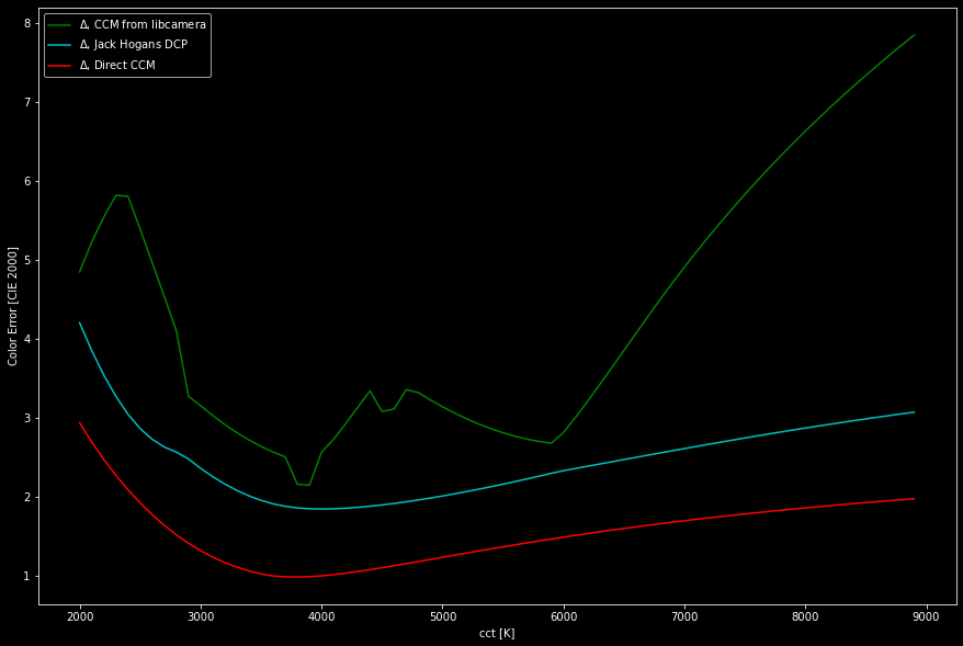
As you can see, the color error has a minima with all three curves (I will later explain these curves in detail) around 4000 K and goes up for warmer (lower cct) or cooler color temperatures (higher cct, less worse). A color error larger than one in the above diagram would be just barely noticeable in direct comparison.
These curves were not obtained by direct measurements, but by simulating actually a virtual light source shining on a virtual color checker and seen by a virtual camera sensor. The simulation is based on the spectral distribution of tungsten-type light sources, the spectral distributions of classical color checker patches as well as filter responses of the IMX477 sensor and the IR-blockfilter in the camera. It’s quite a complex piece of software and I haven’t tested it thoroughly (or even the feasibility of such an approach). So take the following discussion with a few grains of salt.
The green curve displays how close libcamera would actually come with it’s own processing pipeline. This processing is governed by the data in the tuning file, and I did not fully include all processing stages. Specifically, I did not include the ALSC (automatic lens shading correction) and gamma curve (rpi.contrast) modules in the simulation - both would make libcamera perform worse than the green curve in the above diagram.
The jaggedness of the green curve is actually due to the set of compromise color matrices (ccm) in the tuning file. It seems that very different light sources were used in obtaining the set of calibration images the ccms in the tuning file are calculated from, possibly mixing fluorescent and not so perfect LED-based sources with Tungsten or other lamps. Well, just a guess. But the sequence of ccms in the tuning file does not vary smoothly with cct, and it shows up in the color error as well.
Note that if you would base your raw processing on the camera matrix embedded in the .DNG-file, you would end up with results similar to the green line in the above diagram. Otherwise, the JPG-images/preview-images are produced that way.
The cyan line in the above diagram displays the result when using the simplest DCP-input profile for the IMX477 sensor, created by Jack Hogan. The color error is less than the libcamera reference, and it varies much smoother with cct. If you look closely, there are still two tiny bumps in the curve - that’s were the two reference matrices of the DCP input profile are located, slightly below 3000 K for illuminant stdA and around 6000 K for illuminant D_65. In any case, according to the above diagram, you should get better results if you use Jack Hogan’s DCPs instead of the “camera matrix” in a raw converter.
In a film scanning application were the light source (and it’s cct) stays fixed (that excludes color-mixing LED setups with dedicated groups of LEDs for the primaries), it is possible to actually calculate an optimal ccm for the fixed situation (in terms of illumination). The result in terms of color error with such a direct, fixed matrix is displayed as the red curve above. Note that the optimization of the direct ccm is currently not optimized, I am still working on this part.
All the simulations used in the above diagram were obtained by using a tungsten-like illumination source (specifically, a “black-body radiator”). I am still in the process of enlarging my simulation to include arbitrary light sources (for example with the spectrum you displayed in your post). And of course, these simulations need to be verified whether they relate to reality, by actually taking calibration images with a real IMX477 sensor. So there is still work to do.
I must confess that these things are probably not really that important, as different film stock and even different reels of the same film stock show much stronger variations in color rendition than the color errors we are discussing here. To show you what we are talking about, here’s the actual color chart rendering of the simulations above, at a cct of 4800 K:
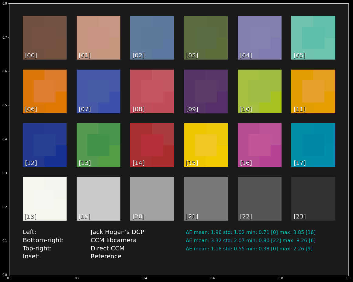
If you look closely, every patch features a central patch - that is actually the color each patch should have. Around each central patch, various other segments show the result obtained with the different processing options discussed. On the left side, Jack Hogan’s input DCPs were used, bottom-right the result of libcamera’s ccms are displayed and top-right the CCM calculated directly for the cct (“Direct”) is displayed.
Again - these color variations would not be noticeable if not viewed side-by-side, and they are definitely smaller than the color variations I see in different reels of color-reversal stock. So all of the above discussion is probably slightly academic…
1 Like
I’ve been lurking here for something like 8 years now, taking notes, and saving links and ideas for later… but I think 2023 is the year that I throw my hat in the ring and try to make one of these things, too.
With that in mind, I’ve been reading this particular topic with great interest for a couple hours today. There is an incredible wealth of experience and resources gathered on this single page.
Back in 2015 I’d been planning to use a monochrome sensor + wide-spectrum RGB light source taking separate exposures for each color channel (if only so I could buy a lower-resolution sensor since I wouldn’t be losing resolution to the Bayer filter). Then I bumped into the Diastor/Flueckiger paper a few years later. Until today I hadn’t heard there were so many serious problems with it, but I’m less interested in the commercial scanner comparisons than I am with that Heidi color restoration comparison on page 15. It had me convinced that narrow-band light sources (critically, with hand-picked wavelengths) were the way to recover maximal signal in the case of uneven dye fading.
So I was especially surprised when I read this:
So far, I’ve only been building my film scanner in my head, so I am ready to defer to the mountains of practical, real-world experience you guys have been accumulating, but I had a question about something I didn’t understand in your example in the same post, above:
For capturing a “real life”, multi-spectral subject, this example makes perfect sense to me. But in the case of a known film stock with published dye absorption spectra, I believe (and maybe this is the source of my misunderstanding?) that whatever is happening at 600nm to the cyan dye should also be happening at 634nm within some linear factor. With the same thing being true for magenta and yellow. At least, that’s what the spectral-dye-density curve chart you posted back in May seems to indicate.
By the time we get to positive film, we’re already down to a linear combination of three colors. So our job is just to pull those back out with as much separation as possible, isn’t it? Figure 7 on page 14 of the Diastor paper shows a set of LED wavelengths that would be good at preventing crosstalk between the dye color “channels”.
Each color LED isn’t picked to maximize the dye response for that channel, but rather to minimize the impact of the other two colors that you want to avoid.
So you end up with a pretty far out there “deep red” LED in the 680’s, but that’s where the magenta and yellow absorption fall off a cliff. So any amount of cyan that is blocked will much more readily pull the original (now-faded) red signal out of the noise. Compare that to white illumination with a standard Bayer filter whose red channel is still very sensitive all the way down to 600nm. In that case the magenta dye is eating a lot of your “red” light and you can’t recover the original reds that are represented by the deteriorating cyan dye.
I suppose if your bolded claim of what to avoid was in the context of a sensor with, say, the IMX477 filter curve you posted above, I would have a much easier time agreeing with it. Those are sensitive at exactly the wavelengths to maximize cross-talk. But in the no-filter, monochrome case where you get to hand-pick each illumination channel’s wavelength, it seems like you couldn’t go wrong and you’ll always get more of the original signal back (in the linear algebra sense of being able to recover something closer to the original vector basis).
Sure, there is going to be a little more color correction necessary than if you were using the standard illuminants, but that’s already something we need to deal with because we’re assuming non-uniform dye fading.
I am sure I missed some important detail that will change my mind again. Please let me know what it was. ![]() Thanks!
Thanks!
That was my initial thinking as well (triggered by reading a Swiss paper), and my scanner operated just with three narrow-band LEDs to maximize the color separation between the channels. But look more closely to the diagram posted above. First, the color dyes have rather broad overlapping spectra. So any color a viewer will perceive created by a combination of broad dye spectra, driven by (normally in those old days) a tungsten lamp. Secondly, less obvious, the curves are differently spaced (compare the magenta spacing at 600 nm with the one at 650 nm) - this is anything than linear. So an arbitrary color will be a mixture of all three colors, in a non-linear fashion. If you want to recreate the viewer’s experience when watching the movie in a scan, you probably have a little bit more to do than simply scanning three narrow-band signals. However, that is still stuff I am researching about, with no final answer.
There is certain a use case where a narrow scan has its advantages: strongly faded film stock. In this case, the subtle color variations the original dyes were capable of are gone anyway. But you probably want to increase the signal-to-noise ratio as best as you can, which can be done with a narrow-band scan.
My very first film scanner actually used narrow-band LEDs with wavelengths chosen in order to minimize the crosstalk between the color channels. It did not work. The results were less than satisfactory. I could improve performance by replacing the red LED operating in the far red with one closer to the green one. In the end, I now do use white-light LEDs in my scanner, and have an improved color output.
1 Like
I’m afraid I didn’t do a very clear job of explaining the method I had in mind, sorry.
The linear combinations I meant were per-wavelength. Taking 1nm steps for simplicity and using the six curves in the chart, you’d end up with 300 pairs of equations of the form:
light = R(λ) + G(λ) + B(λ)
absorption = x1 * C(λ) + x2 * M(λ) + x3 * Y(λ)
The functions are in the range [0…1], taken from the curves above and the final spectral output would be something like light * (1 - absorption) (This is a little hand-wavy. I dug up a couple color science books and noticed after a few hours of study that a timely response here precluded a full understanding and vice versus.) ![]()
We’re in control of the light, so we don’t need coefficients there and the R, G, and B functions for a given wavelength are simply constants that we get from the manufacturer of our LED’s datasheet.
Then, with that many equations you could do a regression or PCA or whatever fancy linear algebra you prefer to best solve for the three coefficients, which would tell you the current, faded concentrations of the dyes in the film.
Finally, you can “correct” these estimated dye levels, run it back through a virtual model using the above graph as-is (coefficients of 1.0), passing through the whole visual-perception model (gamma correction, CIE 1931 to get tristimulus values, etc.) and finally retrieve something closest to the original colors.
The difference between this and trying to do color correction by simply scaling the usual RGB channels in our video editing software is that we would have found the original vector basis for the colors for that particular film stock. Scaling one of those coefficients moves along the film’s “real” color axis instead of an arbitrary one. Moving those sliders around would be like using a time machine to restore the original dye colors and would presumably make color correction easier and more accurate.
Now, that whole process can be done regardless of how you collect your color channels.
My hypothesis has been that using the hand-picked, narrow spectrum values would result in a more accurate solution for those coefficients (and hence, a better reproduction) than are achievable with full-spectrum white alone. Although, @PM490’s idea to add a monochrome sensor + white light exposure and then use channel combinations like Y-B, Y-R, (and even Y-G) to glean even more information about the spectral response that you couldn’t “see” with just your narrow band LEDs is a suggestion I like that I haven’t seen anywhere else.
I suppose the more exposures at different spectral responses you add, assuming you stir the pile of data the right way, the closer the dye coefficients and color axes would get to reality.
This is the kind of thing I was worried about hearing. All of my scheme above sounds very nice in theory and on paper, but if it just doesn’t work out in practice for whatever reason or if my film isn’t all that faded to begin with… this becomes a whole color science research project diversion that prevents me from actually building the machine and getting on with it.
Hearing that you tried it and it didn’t work might have just been a good time-saver for my project. Kicking off my build, my goal for February was to design, build, and test a PCB for a (current controlled, non-PWM) multi-spectral light source that can be used in both a diffuse/integrating sphere situation and a distant, collimated beam configuration (really, just by making sure there are enough fastening points for attaching it to either 3D printed apparatus) for the hopeful/eventual wet-gate.
Reading color science books isn’t getting me any closer to achieving that goal.
To get back on track, I’m going to try and tuck a few high-CRI white LEDs into the already limited space to leave my options open to all three schemes (mono+narrow, Bayer+white, or PM490’s mono+narrow+white). At that point I can try the other methods if I find time, but can fall back to something I know is going to work without any loss of progress or redesigning of parts.
Thanks (for the third time now in as many days? ![]() ) for sharing your hard-earned experience with the rest of us.
) for sharing your hard-earned experience with the rest of us.
@npiegdon - I must confess that you got me thinking again about this again. Well, I must confess that from a physic’s perspective, the whole thing is linear. You have a projection lamp with a specific spectrum shining through the frame, three dyes (yellow, magenta and cyan) modulating the lamp’s spectrum, depending on the image content, and this is what the viewer perceives. So it should indeed be possible to sample this spectrum on three narrow positions and reconstruct the color. I have to think a little bit more about this.
With respect to results obtained with narrow-band LED illumination, this here might be an interesting scan result. As far as I can remember, I used as red LED an Osram type with a center at 660 nm or even 730 nm. The camera at that time was a Raspberry Pi v1 camera, and the film stock in question was AGFA Moviechrome. My “color science” consisted at that time in manual tuning the colors to taste, and clearly my taste was a little bit into the intense color schemes…
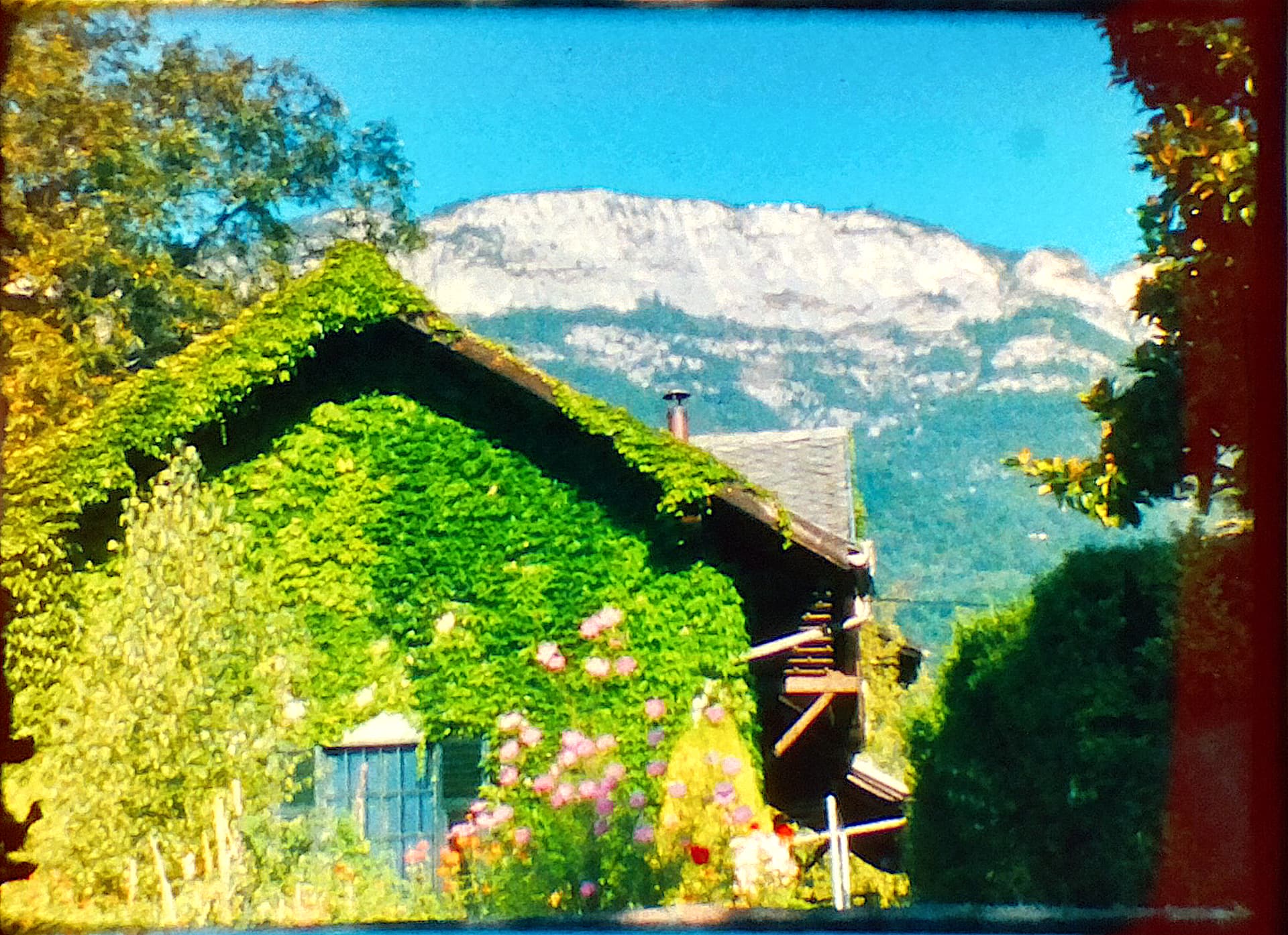
Anyway, one prominent feature of this frame is the redish area to the right of the frame. Were does it come from? It was not visible for my eyes, but the scanner did pick it up.
Most probably this specific camera did not have a daylight filter which covered the whole film frame - while most of the frame did get the daylight filter treatment, a tiny section on the right frame border was not covered by the mostly blueish daylight filter, resulting in this old scan in the redish patch. This was one reason to switch to another wavelength for the red LED, namely to 623 nm.
For people remembering the good old v1 Raspberry Pi camera - this camera had a microlens array which was matched to short focal lengths. This in turn created color shifts when the original lens was replaced by another lens with larger focal length. You can see this effect in the above scan as well - the leaves on the left side of the scan are in the original frame as green as the leaves in the center.
I think, this is something that we all agree on. ![]() And reading books about film is not getting me any closer either, although this one was a good one.
And reading books about film is not getting me any closer either, although this one was a good one.
When you have a hammer, everything looks like a nail. And with my electronic training and limited knowledge of light physics through film components- I then tend to think/analyze this problem as electromagnetic spectrum. And that’s only part of the light behavior, and color science problem.
What is the kind of modulation takes place in the above model? I think is amplitude modulation only.
The film is a filter (absorption), modulating in amplitude the light at every film location (x,y). Three filters actually, which are combined, by human perception.
In the perfect film, finding the wavelength peak absorption for each filter would provide the best choice of illuminant for capturing the RGB components which exposed the original film. The difficulty is that every film make/type may have a slightly different peak. Add to that aging. And let’s not get into the rabit hole of early color films.
Perhaps stating, as I have, that it is best to use white is an oversimplification. What I mean is: If the limitations of availability of LED wavelength, and film make/type/aging, make impractical the wavelength tuning of a tri-band illuminant… what is the best practical alternative? broad(er) spectrum illuminant(s).
Given the constrain of a low-cost RGB sensor, what I thought, is that it would be the best is to maximize the output of the sensor with a good quality white led.
What is best from the sensor perspective?. A higher level of a narrow band color or lower level of a broader band color? either way it would be filtered by the bayer, and integrated into a resulting value. Is it the same? from the perspective of the sensor, no difference. As long as the broad is within the bayer filter.
The white LED approach eliminates the unknowns of mismatching peak dye absorption and the led wavelength. From my perspective, it is a practical method to create an accurate representation of the image that the aged filter is presently rendering.
Which one is it best?: digitally capture the RGB numbers that exposed the film as closely as one can or the RGB numbers that best render the image rendered by the current aged film?
I tend to believe that digital processing, specially future techniques -some that I cannot even imagine- would allow future-post-capture-processing to go from the current aged film rendered image, to as close (or better) estimation/representation of the original image.
The POC VECOSCAN is an interesting approach to illuminant wavelength tuning.The filter technique would be a way to tune the wavelength of the illuminant, to match the peak absorption points of specific film make/type/dye. From what I gather, is not used in that way, instead it is capturing additional wavelength for the purpose of multiple, yet discrete spectral representation.
Yet something that is possible, and best, may not necessarily be practical, and efficient.
On the other hand, we can keep future options open by the choices we make at scanning (particularly led wavelength). Some of these choices are in fact digitally irreversible (like resolution, or the narrow LEDs).
@cpixip did you use a mono Raspberry Pi v1 camera for that experiment? Because otherwise the bayer filter could have been interfering?
@PM490 Do you know what that POC VECOSCAN is using as a light source? Is it an Halogen bulb that passes through an adjustable filter? Does anybody know how this filter works, it seems to be a two stage thing.