@Bill - this was an unmodified v1 camera. So yes, the Bayer-filter was in this game, sort of. The thing is that the camera’s Bayer-filter becomes nearly irrelevant when working with narrow-band LEDs. The narrow-band LEDs sample the broad filter response only on in a narrow range. Of course, the LED light will be reduced by a certain factor, depending on the amplitude of the filter response curve in that narrow LED range of wavelengths. In my setup (at that time) these modulations by the filter response curves was taken care of by adjusting the LED intensities in such a way that the light shining through the sprocket hole (not shown in the above image) was neutral. To summarize: yes, the Bayer-filter in front of the sensor was interfering, but that was taken care of by adjusting the LED intensities to counteract this.
This presentation describes the project, check minute 8:00 where they describe the scanner particulars. It is described as “broad band light source with a linear variable bandpass filter”.
Interestingly the scanner also has a selectable diffuser filter to capture with our without the diffuser (around minute 12).
The presentation also makes an interesting illustration of the sensor spectral bands vs narrow RGB LED (minute 13:30), summarizing some differences between RBG and broadband illuminant.
Well that linear variable filter is not something I am going to use any time soon, it seems too expensive compared cheaper to multiple interchangable LED modules. I don’t know if anybody has tried with dichroic RGB filters in front of a mono sensor?
Did you @cpixip use a tri-band light source at each exposure, or is this a serial method (what I assumed). I was planning to use a mono sensor and serially exposure the film with RGB + IR (scratch/dust reduction attempt), the idea being more dynamic range, resolution etc. However the selection of a good affordable mono camera is not so easy.
@Bill - no, I used three separate LEDs with different center wavelengths. Their light was mixed via an integrating sphere. Camera-wise, I started with a Raspberry Pi v1 camera, switched later to a Raspberry Pi v2, only to learn that these sensors have micro lens arrays designed to work with short focal lengths. In my setup with a Schneider Componon-S 50, they were producing color casts which can not really be corrected. This triggered a switch to a see3cam cu135, a USB3-camera, also with a Bayer-filter. I finally ended up with the Raspberry Pi HQ camera which is the camera I am currently using.
For the narrow-band LED light sources, I tried quite a collection (451 nm “deep blue/royal blue”, 470 nm “blue”, 521 nm “true green”, 623 nm “red”, 660 nm “hyper red”, 730 nm “far red”, among others). The final combination I used with three different color light sources were 470 nm “blue”, 521 nm “true green” and 623 nm “red”. I abandoned the three separate LEDs because of the difficulties of the color science involved with such a narrow-band illumination. I am still doing research in this directiob, but I use now the Osram Oslon SSL80 CRI95 neutral white as only lightsource; I need to use LEDs mounted on a 10x10 mm PCB with my integrating sphere and I had these LEDs in my part box.
I am operating the HQ camera at a resolution of 4056 x 3040 px which is more than enough for my grainy Super-8 material. The dynamic range challenge is handled by taking 4 different exposures of each frame - a highlight frame, a prime scan plus two shadow scans. These images are normal 8 bit/channel output images from libcamera, no raw files. The 4 exposures are normally sufficient to capture all necessary image detail; for some film stock and extreme situations, actually a third shadow scan would be necessary. But I do not really bother with this, as scanning speed is more important for me than to capture the extreme film grain of image areas which will be close to black anyway in the final product.
I have run tests with capturing raw images instead of jpgs, but I do not really like the development step you need to do when working with raw files. I want most of the scanning process to be more or less automatic. Well, I am still doing experiments here as well…
That’s interesting. I’ve seen some film with those sorts of discolorations on the sprocket side, but never on the farther side. Those differences were visible to my eye and in any color light though, so maybe it was a different phenomenon?
That’s a great find! I’d found most of the topics discussed in there, but all piecemeal, scattered across forums, etc. and without so many lovely illustrations. Thanks for sharing that.
I was prototyping something like this a few years ago and ran into a couple snags that might be helpful to hear about ahead of time:
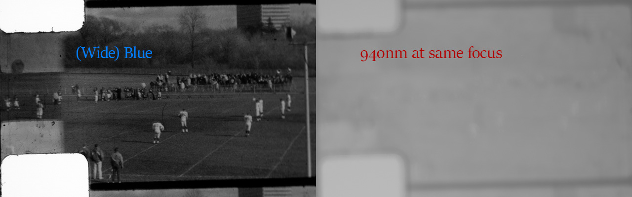
Here is the same frame using the same camera focus (nothing moved between these exposures) between wide-spectrum blue and a 940nm IR LED.
It actually took me a while to realize this was happening. (I thought I was going crazy and just kept accidentally bumping something in my test setup. ![]() ) It wasn’t until I also tried out a 1050nm IR LED and the out-of-focus effect was ~2x worse that I realized it wasn’t my fault.
) It wasn’t until I also tried out a 1050nm IR LED and the out-of-focus effect was ~2x worse that I realized it wasn’t my fault.
What was going on was longitudinal chromatic aberration. If the lens isn’t optimized for IR (and I’ve been told not many are), you may need to change your focus position between exposures.
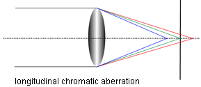
(At the time I had been using a lens way outside of its design range so even my color channels had slightly different focal planes, so I’d just included the “refocus after each exposure” into my design requirements. I think the better answer now is to just get a lens that doesn’t need to do that. hehe.)
I hit the other snag once I got the 940nm IR channel in focus:
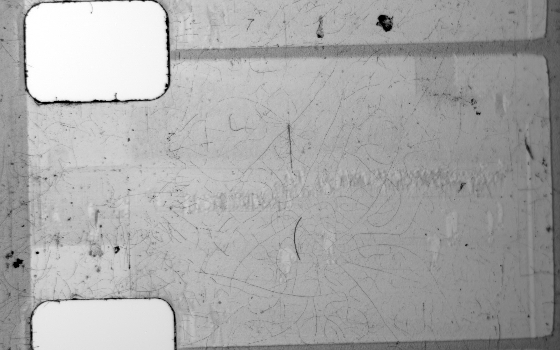
You can still see some of the scene and not just the dust/scratches! Again, I thought I was doing something wrong. Maybe I wasn’t far enough out into the IR range? So, I bought that 1050nm LED. It showed similar results.
This remained a mystery to me for another four years until just a couple days ago. I noticed a section in the Wikipedia entry for Digital ICE that I’d never seen before: Kodachrome in particular uses IR-sensitive dyes, so IR cleaning is much harder with that specific type of film.
It sounds like some scanners have made an attempt at finding a workaround. I haven’t been able to find much information about what they’ve changed.
There are some dark-field illumination (shining a light in from the side) patents linked on the same page that discuss gathering a dust/scratches channel by using the scattered reflections that make it to the camera from the side-illumination. Since 100% of the film I need to scan is Kodachrome, now I’m investigating that direction instead.
So, if they can help at all, here were my lessons learned:
- Unless your lens was designed for it (like these?), you may need to refocus for each IR exposure.
- If you’re scanning Kodachrome, this may be even trickier.
EDIT: Ha! I just noticed that four year old Reddit reply I linked above (“been told”) also mentioned the second snag but I don’t think I knew anything about the film stocks at the time, so I ignored that part! That could have saved me a lot of wondering in the meantime. ![]()
Hi Gents have been following all the post in the various forums as about to embark on my own build based on details gleaned from all the contibutors here. I found the original ref to the way HP overcame the issue of getting higher quality back in the day made for very interesting reading you can download the design excerpt from here - https://web.archive.org/web/20110607100019/http://www.hpl.hp.com/hpjournal/pdfs/IssuePDFs/1993-08.pdf
Go to pages 52 to 57.
I actually bought on of these back in the day and still have it as i thought originall i might be able to use it to scan the Super8mm rolls i have - there was a post about doing that back in the day and then seperating out all the frames and then stitching them back together to make one harmonious file.
Anyway thought you might be interested to see how HP did their scanning optics very ingenious back in the day…
@npiegdon Thanks for that information, I already knew (probably also your posts somewhere) that Kodachrome was a bad candidate for ICE. However when I look at your sample it looks better than I had hoped. The scratches dust are clearly visible, I think I can filter them out of the image ( I’ll attempt it in Photoshop/GIMP). As an alternative I was thinking of doing something like wet scanning, although I don’t know how dangerous that is to use with kodachrome film stock. My scanning process will be slow enough for the film to dry though.
BTW, What kind of sensor and lens did you use?
I’m also (very) interested in trying to build a wet-gate for my film scanner. In terms of safety (to the film), the old standard was to use Perchloroethylene (or just “perc”), but that stuff was so horribly toxic that its use has all but been banned today.
The key to a good wet-gate fluid (besides not destroying the film) is that its index of refraction has to match the film base. Then, you get that cool disappearing beaker effect where the scratches simply disappear during projection. And that way you can use collimated light (instead of diffuse) which boosts the contrast ratio back up to where it would have originally been during normal projection.
In 2003, when the world was starting to crack down on the use of perc, Kodak released this article which includes a section on an alternative. The name of the stuff is isobutylbenzene (IBB) and it matches the film base’s index of refraction just as closely as perc, but instead of being highly toxic, as best as I can tell from all the MSDS sheets, it’s about as safe as handling isopropyl alcohol. I’ve been trying to get my hands on some for a couple years, but chemical supply places require a lab or commercial address or they can’t ship it. It’s been frustrating.
While exploring alternatives, I discovered the list of things it’s apparently “safe” to dip your film in on this conservation treatment page. About half-way down there is a table that shows a list of chemicals that can clean film. Isobutylbenzene happens to be on that list, too, as a good cleaner.
The table on that page seems to be from a more complete list I also stumbled upon a few years back on Kodak’s own site. I couldn’t dredge up the Wayback Machine link for it just now, but I saved a PDF of the page back then. Here is the more complete table:
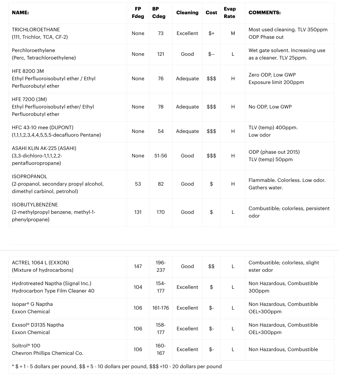
Searching for the exact words in there, you can find a few forums here-and-there where someone copy-pasted the contents of the table (losing all formatting in the process) but Kodak seems to have taken the original page down.
Anyway, I’ve meticulously gone through the list to try and uncover the index of refraction of each of those as a possible alternative to IBB. The naptha-based ones near the bottom are close, but not quite as close as IBB. But since they’re much easier to get your hands on (I found some Isopar G listed on Amazon ![]() ), I was going to try them first and see how close it gets to making the scratches disappear. If it cleans the film a little while I’m at it, all the better.
), I was going to try them first and see how close it gets to making the scratches disappear. If it cleans the film a little while I’m at it, all the better.
Re: the lens and sensor, it was a Gen1 Sony Pregius IMX249 sensor (from a FLIR industrial camera). I had it attached to a Canon EF 100mm f/2.8 Macro USM through a long chain of adapters. I had the lens much farther from the sensor than it normally is on a Canon camera body, so things were already behaving a little strangely, and then IR performance is probably the last thing they worry about when making those.
The “enlarging lens” setup that most people seem to have settled on here seems like a better answer. Coincidentally, my 50mm f/2.8 Componon-S just arrived from eBay today. ![]()
From my experience scanning still photographic negatives I believe this is correct. The key to understanding the reproduction of color in film is realizing that the actual colors of the dyes in the films somewhat arbitrary, and that what actually matters is the density of the dyes in each layer. You are not trying to take a photo of an object ( the film negative) but rather to map the density of each dye layer to a color channel. While it is possible to do this with a white light, preferably one with a high CRI, correcting the colors via this method involved applying a gamma correction per-channel, (because you end up getting channel crosstalk in areas where the dye response to light is non-linear), which is difficult and time consuming. By use narrow wavelength RGB LEDs, optical filters or some other method of splitting the light into narrow bands of red green and blue you can avoid this. I believe RGB LEDs are generally sufficient. If you crack open pretty much any old commercial film scanner you will find that they contain an array of RGB LEDs, though the key here is that the wavelengths are important. I’ve found that something around 640nm, 535nm and 660nm works well for most color negative stills, and I’m guessing the same is true for color negative motion picture film.
hi,
I’m currently in the phase of collecting parts for my normal8 scanner, so far (and from previous photo flatbet scanning projects) I have the raspi4, raspiHQ cam, a componon S 50mm, an old bellows and steppers with an Arduino Adafruit Stepper board.
The lighting is the missing part and I really want to do bracketing when scanning by adjusting he lighting as @cpixip does, but this part is completely new to me.
Now my questions:
- I’d go with a good white led ( Cree CXA1304 COB-LED, 366lm, 4000K, CRI 95) - what’s the recommended way to control this (arduino, raspi?)
- is there code for this controll already available
- what would be the simplest hardware setup?
- will three white leds work with the integrating sphere STL of @cpixip ?
lots of info to process, but its a tempting rabbit hole ![]()
greets
simon
@d_fens: let me try to answer your questions as good as I can:
-
Good white led: that’s what I actually ended up after starting with separate LEDs for the red, green and blue color channels. The reason is that I (currently) believe that the color science is better when using white light LEDs instead of narrow bandwidth colored LEDs.
-
code for control: have a look around the forums, there are various systems described for controlling LEDs. In my opinion, try to stay away from anything which uses PCM or the like, i.e., where the amount of current through the LEDs is controlled in an off/on-way. While cheaper to implement, your camera might pick up the on/off-pattern during the exposure of a frame. My own implementation used an Arduino to control DACs which would specify the current level for each LED. Nowadays, the Arduino controls only the stepper motors, and the DACs are driven by the Raspberry Pi which also grabs the scan.
-
simplest hardware setup: for illumination purposes, you could actually get by with suitable chosen resistors and a regulated power supply. You will not need to change the level of illumination that much if your system is tuned in. Or you could use a DAC-driven current source as I do. This as well as some other designs have been described here on the forum. Feel free to ask questions!
-
will three white leds work…: certainly. That is my current setup. Be sure to check the integrating sphere approaches other people have posted here in the forum. Some feature larger spheres which will allow you to work with brighter LEDs or more LEDs. My setup is not really that bright. I am using Osram SSL80 LEDs, they have only 90 lm. But they were the only white light LEDs I could find in the small 10x10-footprint I designed the integrating sphere for…
With respect to exposure fusion (Mertens) - that is a very easy to use process and it comes free with the opencv library. In my opinion, it outperforms in terms of result and usability alternative approaches like calculating a real HDR (Debevec/Mailk) followed by the necssary tone-mapping step too much algorithms available for my taste) to get the data into a classical video format. Yet another approach (which I am currently investigating) is to capture raw images and pipe them directly into DaVinci Resolve.
@cpixip thanks a lot for your reply!
earlier today i just uploaded your sphere and gate stl to a 3D printing service and i’m looking forward how the delivery will look like once it’s here, i’ll keep you updated how that turned out.
I found this 10x10mm PCB with versions for different LEDs, now its a bit of research to filter through the mouser list of compatible LEDs and their characteristics and settle on one just to get things started and then improve from there.
If i did my research right, then a Mean Well LDD-H-Series driver would be a easy way to control brightness of the three leds via PWM either from the arduino or raspi, but i’m not there yet.
Regarding the hdr generation i also prefer the automated way and another thing i want to try out then is to use this pytorch model to colorize some of the old monochrome movies, but thats for another day
that’s an interesting find!
This is one of the drivers which use PWM (pulse width modulation), basically varying the duty cycle between on and off to simulate a certain current through the LED. The LED will follow this on-off pattern, and if the PWM-frequency is not high enough, it will affect your image capture. There might be some sort of funny pattern visible in your capture.
From the data sheet, it’s not clear what the actually PWM-frequency is. “100 ~ 1KHz” can mean 100 Hz to 1.000 Hz (which would be rather low), or 100.000 to 1.000 Hz (= 100 kHz tp 1kHz). If the max frequency is 1 kHz, I would suggest to do a test with these units. Drive them with 1kHz PWM and illuminate an evenly lit piece of white paper. Choose for the HQ camera the exposure time you probably will work with and adjust the f-stop of your lens in such a way that the average pixel value is around 128 (the center of the 8-bit range). Now capture a few frames and look for stripes and other intensity variations. If there are non, your fine. Otherwise, chose a PWM module which supports a higher PWM frequency.
Adding to @cpixip comments to provide nuance in regard to PWM controlled drivers. In an oversimplification, I would group these in three types.
First ones, including the Mean Well, switch on/off the led based directly on the PWM control input, the current accross the LEDs will be close to a squarewave.
The second group, are switching current regulators, also with PWM control input. On these, the current across the LED is typically in the form of a sawtooth wave. The Fentobuck is a good example of this configuration, here the datasheet for the IC, see IL representations in Page 10.
Lastly, there may be some designs, that use a PWM control input for simplicity, but are providing a constant current. The drawback of this design is that to achieve constant current the PWM input is converted (low pass filtered) to a DC, which decreases the speed of control. My first driver design is based on this configuration, and this video shows the controlling input (PWM) and the resulting DC output which controls the LED current. The convenience of a single wire for 16bit control is at the expense of a very slow response (low pass filter).
The practical testing suggested by @cpixip is spot on.
thanks guys for the quality replies!
its great to have a simple overview over the types of LED drivers, i’ll test the behavior once the hardware arrives.
on a sidenote @cpixip
i feel newer COB often have a 13,35x13,35mm plate, i tried to fiddle with the STL of your sphere in blender and FreeCAD by scaling everything but the gate and screw channels by 1.35 but failed, do you think this is easily doable?
Well, hard to tell. This is an old design, and as far as I remember, the geometry of the LED-holding plate was carefully chosen to not allow direct light into the film frame. Also, some dimensions were adapted to the specific tolerances my 3D-printer was using at this time. Simple rescaling might work, but I would need to have a look at these old data files for a more detailed answer.
One of the reasons why I suggested to you to look at newer designs is that these newer sphere designs support better mounting options for newer LEDs.
If you want to stick to my old design anyway, please note as well that I needed to add active ventilation to the design - otherwise, my LEDs were running to hot for the plastic…
@cpixip got the prints and they do look good, now i’m rebuilding the sphere in freeCAD and try to make it fully parametric, so it can be adapted easily for different led PCB types and sphere sizes - i will post the cad file once done .. recursive rabbit hole alert ![]()
@cpixip would like to brainstorm an idea and get your feedback.
I was looking into an alternative design, to reduce the space needed for the sphere, and to also increase the area available for led placement,. Came across these dome lights used for machine vision. Below an example.
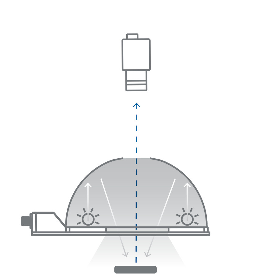
These are used to iluminate a target object, at the bottom of the illustration. I thought the target object could be a nice white-flat-reflective material, and the film would be between the top of the dome, and the camera.
With these, one can build a PCB board in the shape of a ring, providing plenty of surface for more LEDs (quantity and type of LEDs), removing the constraint of the typical sphere port.
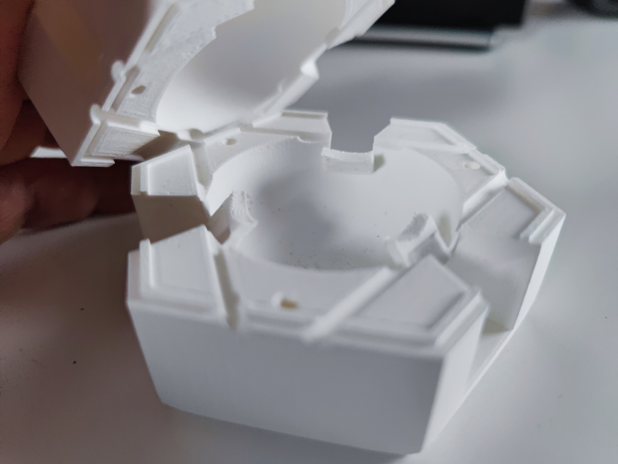
I purchased these aluminum half domes, with the intention to assemble an integrating sphere. I chose the 90mm diameter (100mm rim to rim) looking for a size big enough to do 16mm film.
But I am thinking these would be perfect to experiment with the dome-light configuration.
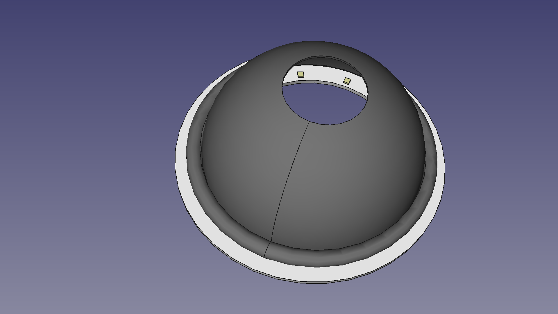
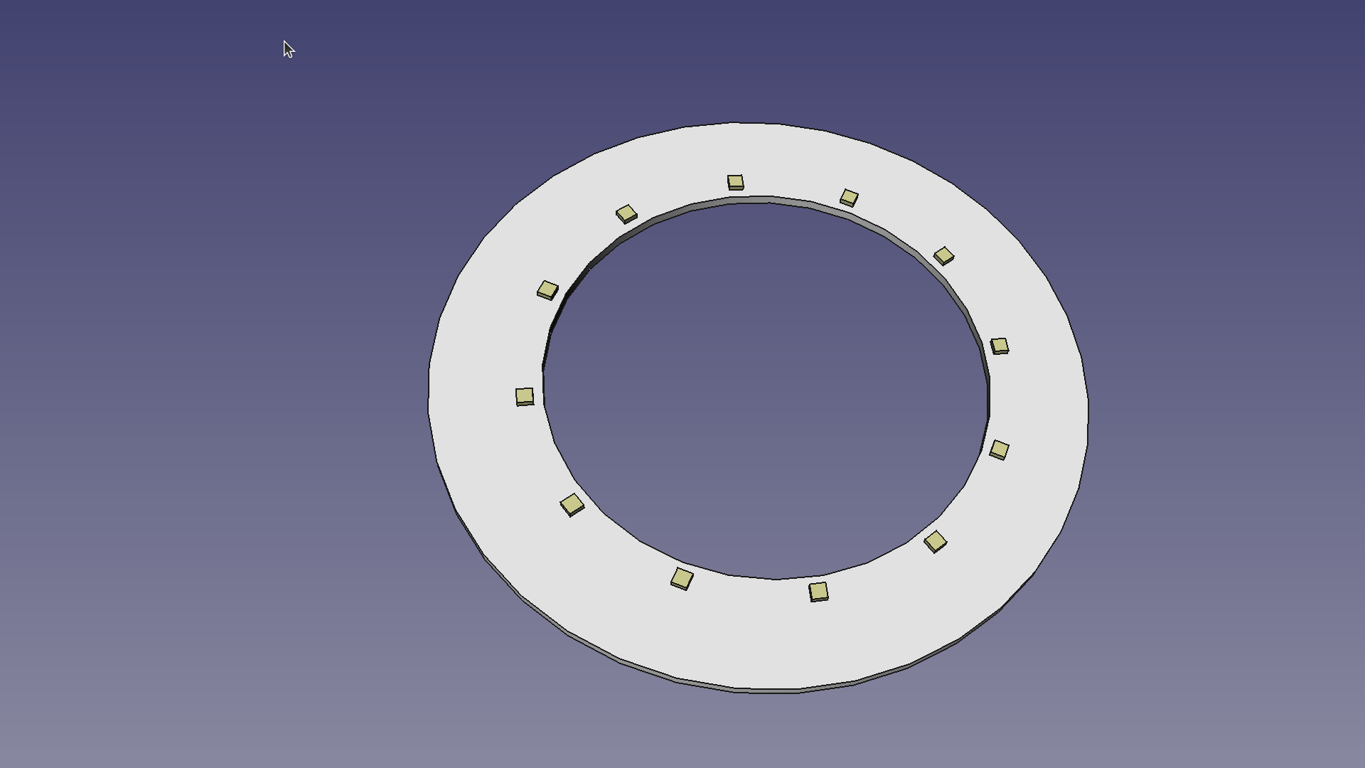
(Angle chosen to show the LEDs for Illustration, which would not be seen by the sensor)
Before chasing this rabbit hole, would like to brainstorm it a bit and get some feedback from the forum, perhaps someone has tried something similar already.
PS. @cpixip an interesting possibility of this configuration is that it may be possible to tune the target to create a band of interest, that it is not as narrow as a color LED. This may not be practical, but it opens some crazy experimental possibilities.
Hi Pablo,
I think it would be worth a trail to simply put the camera below the dome. That is: drop the idea of illuminating a white-flat-reflective material with the dome, use the light from the exit pupil directly.
The thing is: while an integrating sphere is technically/theoretically the optimal solution for a homogenious illumination of a small exit pupil. To prove this, one assumes a coating inside the sphere which is lambertian (that is, light is scattered back with a cosine law) and the entry pupils for light as well as the exit pupil are very small compared to the total surface of the sphere.
In a real design, neither of these assumptions are satisfied, mainly for cost/space reasons. In fact, even really coarse approximations of the integrating sphere idea will work - depending on your requirements. As an example, in my photolab I used a 6x6 color enlarger; the light of the enlarger lamp was filtered by adjustable filters in three different light paths and than mixed in an approximation of an integrating sphere: a simple hollow box coated with white plastic, about 8x8x16 cm in size. The filtered light entered on the top of the box through a hole in the side, got mixed and finally exited the light box through the bottom 8x8 square. The entry pupil was therefore perpendicular to the exit pupil. I can assure you that this setup works perfectly for print enlargements of medium format color negatives.
So what is important? First, you need a large enough mixing volume. It it’s a sphere - fine. But other geometries work as well. Second: you need to make sure that any light has been reflected several times in a random way before exiting through the exit pupil. That is: you want a highly reflective, but very diffuse coating inside your mixing volume. What is often overlooked at this point: you need to use appropriately based baffles to avoid any direct light path between the entry pupils and the exit pupil.
So: closing the top hole in your setup above (where the camera looks through) and adding a very small circular ring to prevent a direct LED-light path (alternatively: move the LEDs slightly lower than the exit pupil) to the exit pupil should give you not to bad illumination setup if the half sphere is large enough.
Thank you for the insight and feedback.
Exactly, in our case the exit port is quite large.
I did some photography at early age, and know exactly what you mean.
Perfect design recipe!, thanks. In the integrating sphere, the setback of the LEDs in relation to the sphere surface, at the input port provide the baffling. In the oversized-ping-pong sphere, I did not have any setback, in other words the LEDs are at the surface of the sphere, and while there is direct light path between the LED and the output port, it is at an angle that -luckily- is above/below the film path. So I know exactly what the problem is.
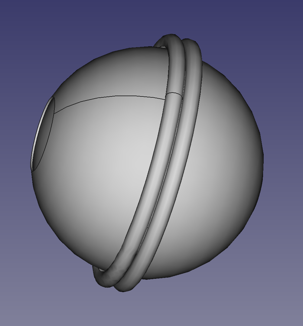
If I understood correctly above, your suggestion would look like this.
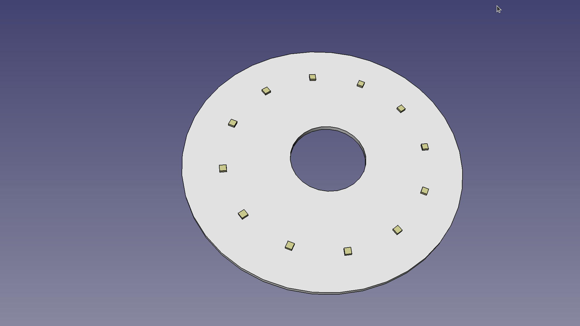
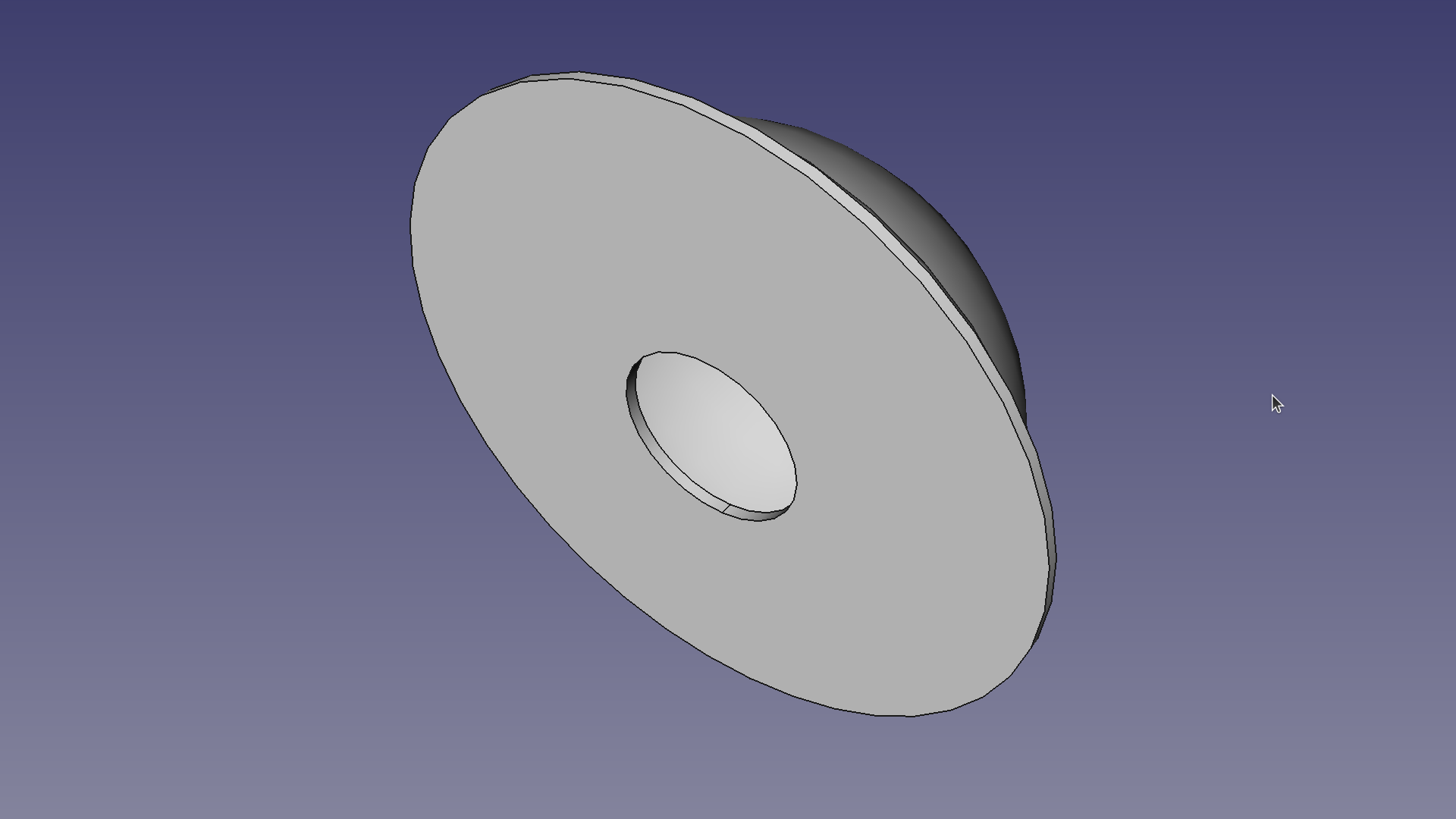
For reference, the sphere edge-to-edge diameter is 100mm and the port is 30mm. This will provide plenty of area for LED combinations.
I also think the enlarger configuration is also worth looking at, since it has the potential of an even smaller illuminant footprint. I can probably assemble a mockup with my current PCBs (2 x 4W).
Thanks for the feedback Rolf.