The Backlight

Interesting. So you basically think I’d do better with a white light LED source providing I managed to find one with a flattish spectrum (not like the ones I had which look a lot like your graph), as compared to narrow band R/G/B sources? I guess the response of the filters on the camera image sensor must come into it as well.

It’s a lot easier with white light sources - no problems with casts across the image from poorly mixed R/B/G sources.

I see you said you used an integrating sphere to even out the light source. I wondered about that when I did it - something like some old enlargers used to have. Couldn’t think of an easy way of making one at the time so used opaque diffusers. Worked OK, but the diffusers do soak up most of the light output. I suppose these days one might be able to 3D print something.

There is an excellent spectrometer app called Colour Grab for Android devices. It can be calibrated using a white card in natural daylight. The result is as accurate as necessary in my opinion (1%).

Well, yes. Whether this is something worthwhile to consider is a different issue. What a scanner’s camera sees in its three color channels depends on how much energy the light source is supplying at a specific wavelength, multiplied by the camera’s filter response at the same wavelength. The actual output of each camera color channel is than this combined value integrated over the whole spectrum of wavelengths.

Now consider hypothetically a narrow dip in the curve of a dye of the film stock. Further assuming that by chance your narrow red LED just happen to sample in this dip, you will get wrong color values. With a broader spectrum (white light) the risk of such alignment is less, if not non-existent.

Well, that’s certainly a heavily constructed example, and a highly unlikely situation given the spectral curves in place. But averaging over a broader range of wavelengths will reduce the risk of such a thing happening.

On the other hand, with strategically chosen LED wavelengths, you should be able to increase color separation for a specific film stock.

When I started to design my light source, I actually tried to get hold of the camera’s sensor curves (which I achieved) and the spectra data of the LEDs used (same). What I did not achieve at that time was any good information about the spectra of normal film stock. Nevertheless, I created a little program to choose the “optimal” wavelengths for my red, green and blue LEDs. The result was ok, but not “sparkling”. I ended up “tweaking” my setup simply by trying out different LEDs. The color definition of highly saturated red tones was still not satisfactory - I solved this by exchanging the stock IR-filter of my camera (which is a Raspberry Pi HQ camera) with a more expensive block filter.

Given all the possibilities we nowadays have with respect to color grading, I actually do not think that all these consideration do have a big influence with respect to scan results.

Well, while this is a nice app, it is only locating colors in RGB-space. This will be of not much help in the context of the spectral curves we are discussing in this thread. What you really want to use is something which can measure the energy present at a specific wavelength. These units are called spectrometers; basically, these are units with a diffraction pattern which is projected onto a camera’s sensor surface. Here’s is a link to one based on a Raspberry Pi camera

and here’s another one based on a smartphone/webcamera

The little attachment connected to the smartphone contains actually the little diffraction pattern you need for spreading out the light spectrum onto the camera’s sensor. Here’s

as a 3D-printed version of this tube, and here’s

an example of the software which is needed to calculate a spectrum out of the camera image. There are example spectra on this website as well.

A few of points of information for context, from what I have seen.

  • Color film density curves are typically based on 3200K.
  • Sensor sensitivity curves are typically based on 3200K.
  • Film structure is not additive (dies are Yellow Magenta Cyan), so one starts as white light, and the film substracts.

If one is setting the illuminant to a color (R G or B) the capture would be the resulting product of the LED and the sensor sensitivity for the particular wavelength. And the goal is to capture what the film density did not substract.

For illustration, below is the sensitivity chart for the Sony IMX477 (sensor used by the Raspberry HQ) overlapped to the density chart of Kodachrome.

As pointed by @cpixip using a narrow led band would then make the capture very dependent of the wavelength chosen. Selecting the LED basically selects what one is scanning, but more importantly what is not.

Another alternative, White + RGB. That’s the path that @matthewepler chose for this iteration of Kinograph selecting an RGBW LED, and constant current to control each channel as needed.

All of the above is in the context of a color sensor. But I think illustrates that when selecting the monochrome camera + RGB LEDs it shows how critical it is to select the right LEDs, which in turn decides what is not scanned.

2 Likes

I thought it would be interesting to combine all this information in one chart, combining Light (LED), Film (Kodachrome), and Sensor (IMX477/Raspberry Pi HQ minus filter).

For the purpose of illustrating the substracting nature of the negative, the Diffuse Spectral Density was plotted upside-down to what the datasheet presents.
In short… It all starts with what the light source can provide, in this case the White LED, then…

  • Cyan let that portion pass (blocks Red), then captured by the Blue+Green pixels.
  • Yellow let that portion pass (blocks Blue), then captured by the Green+Red pixels.
  • Magenta let that portion pass (blocks Green), then captured by the Blue+Red pixels.
3 Likes

Fantastic! Looking specifically at the red part of the spectrum, it seems that one might encounter issues here. First, the input from the magenta dyes will end up in the green channel as well, because the green filter is not at 0%, but somewhere above the 10% mark. Second, both the white-light LED as well as the Sony IMX477 feature a fall-off, starting at 600 nm for the sensor and at about 640 nm for the LED. That is about the same wavelength were the magenta dye is starting to become relevant (with diffuse spectral density going over 90%).

Indeed, I encountered some time ago issues with the color definition of intense reds using the HQ camera - albeit with a discreet RGB-LED setup (not a white-LED). Now, replacing the stock IR-Filter with a better one resulted in improved color definition.

The blueish stock IR-Filter is responsible for the linear fall-off in the red channel of the Sony IMX477 starting at 600 nm. Here’s the plot of the IR-filter of the Raspberry Pi HQ camera measured by myself (the Raspberry Pi foundation published a very similar filter curve some time ago, but I can not find their data on their website any longer):

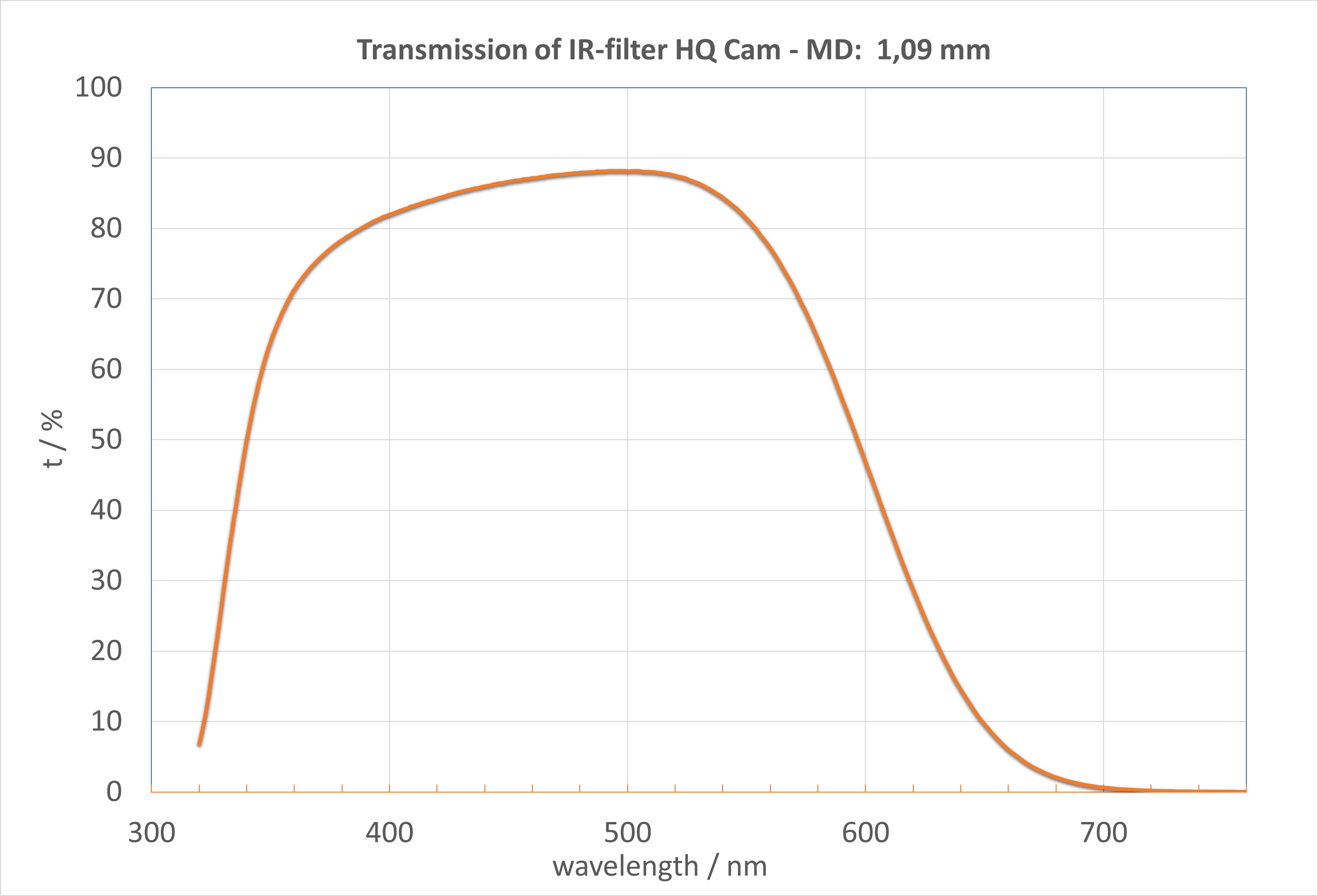
One can clearly see how strong the filter blocks light in the red color parts. Just for fun, I replaced the stock IR-fitler with this one,

image

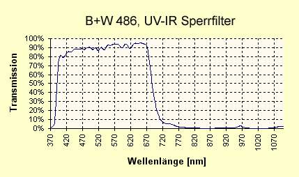
which resulted in a better color definition in the red part of the spectrum (at least in my setup).

1 Like

Glad you like it. Thought it was an interesting representation of the issues with light.

Can you elaborate on the setup to do this measurement?

I was watching at this youtube Pi Spectrometer and was considering putting one together for doing a bit more light measurements, rather than relying on manufacturer specs.

On the IR HQ filter note, I recently got the camera, but haven’t had the time to play with it, and was thinking about removing the filter and leaving the sensor exposed.

Well, the machine which was used for this measurement is a professional spectrophotometer which is able to measure transmission values from the UV to the near IR (specifically, from 185 nm to 900 nm).

Basically, it uses different lamps, a cascade of different diffraction patterns and variable slits to single out a specific wavelength. This light is than passed over two separate paths to a photomultiplier. One of the path has the filter to be measured inserted, the other is empty and is used as 100% transmission reference. The photomultiplier is switched optically between the two measurement channels. It’s a quite complicated machine.

Be careful - the RGB-filters used in the sensor are not functioning in the near IR range. They are all basically transparent here. That’s the reason for the IR-blockfilter. Without an IR-blockfilter, you will get a dramatic color spill ruining your colors. Check some example images taken with the Raspberry Pi foundations “NoIR” camera to get an idea how the removal of the IR-filter affects the colors. You will absolutely need to put another IR-filter in place when you remove the stock filter. Also, of course the color balance will be shifted if you have replaced the original filter. So the original color matrices which are used in the Broadcom image stack are strictly speaking no longer valid. Of course, potentially you could try to handle that within the context of the new libcamera-stack - for my taste, this new “option” is however still something I will avoid; I do not consider the existing implementation to be production-ready.

that is actually the spectrometer I linked above. Seems to be a decent development. Certainly usable for checking LED curves. However, for various reasons I do not think that transmission measurements with such a setup would be very meaningful (in short: non-linear camera sensitivity, noise floor, constancy of the light source during measurements, etc. ). You would need to measure (as described above) first the pure light source (to get the 100% transmission line) and than measure the filter in question. Transmission would be measurement 2 divided by measurement 1.

Thank you @cpixip.

That’s what I thought, but worth checking.

Good points. I was thinking about experimenting with IR sensing, some scanners use it to detect dust. But you are right, would have to consider the light source or a filter as part of the lens.
I do see as problematic the factory filter response for red. The filter you suggested is great, thank you.

Understood.
Primary use I was thinking would be to have a real life measurement of the LED, mostly for qualitative comparison of light sources rather than for quantitative measurements.
Great exchange, thank you for the information.

You can read about the YUJILEDS here and here. They have peaks in the spectrum, but I think it’s more about the spectral coverage than whether there are peaks or not (I’m not a lighting expert). The white LED lights of the past were not capable of this so they were missing a lot of the spectrum and then even if you pair a light like that with a really good top-of-the-line camera it doesn’t matter it will me missing a lot of detail and unable to reproduce the colours.

Thanks, very interesting.

These LEDs employ the same technique as classical “white”-LEDs: pair a single LED with a dye converting part of the LED’s light into other wavelenghts. It’s “just” an optimization to obtain a desired spectrum. In the extrem case, you take an UV-Led and create the whole visible spectrum purely through the appropriately designed flourescent dye.

I’ve found some other relatively high CRI (97) white LEDs that I’m going to try - they were quite cheap, so it’s worth the experiment before looking at anything more expensive, I think.

The benefit is I can easily fit these LEDs into the current mechanical and electronic design. However, unless it works absolutely brilliantly, I’ll probably then experiment with a 5x5 matrix of R/G/B LEDs driven by three constant current sources for comparison.

From what I’ve read above which is most ‘illuminating’, I’d expect the R/G/B approach to give better colour separation than high CRI white LEDs, ie saturation, but possibly with worse colour accuracy. In the end though, it’s completely subjective, because I am just converting old family home movies so all that really matters is the family’s opinion.

An added problem is that the films (mainly 1960s) have not been well looked after, and in some cases there is fading. Not only that, in a lot of cases the original exposure was atrocious, and transparency film like Kodachrome or Ektachrome has a really narrow tolerance of under/over exposure, but there’s not much one can do about that.

As a point of interest I do have a 35mm film scanner I still use occasionally for slide scanning. It gives phenomenally good results (on well exposed slides). Must look into what light source that uses.

The White LEDs I selected have a Vf of 9V for 100mA. I would speculate that these use more than one LED junction under the die, perhaps of different wavelengths to achieve the better response. I have no information to support this speculation but it is consistent with the high Vf.

Possibly, though I have seen LEDs that are simply two or three identical LEDs in series - higher light output at higher forward voltage. Could be either, I guess.

Update on new light source:

Have now fitted the new white LEDs. These are BRIDGELUX BXEN-40S-11M-3C-00-0-3 COB LED (Neutral White, 150 mA, 97 CRI, 116 °, 56 lm, 0.5 W, 4000 K, 3.1V, Rectangular). Five in series, run at 125mA (total drop 15.03V) arranged in an ‘X’ formation with two diffusers. They were pretty cheap, no doubt the YUJILEDS might be better but at 100x the price I thought I’d try these first.

Wasn’t sure what colour temperature to go for. The original film is designed to be illuminated by tungsten lamps at around 3000K viewed with the human eye, but on the other hand the camera was designed for daylight (5600K). Indecisively compromised on 4000K, seems OK.

Results are slightly better than the original LEDs that were Lumileds from 10-12 years ago (estimated at 75-80 CRI with a big hole in the spectrum), but not massively. Greens were better (green/blue is where the big hole in the original LED spectrum was), and generally colour separation was slightly improved. Sufficiently better that I may not proceed with the R/G/B experiment, don’t know yet.

Do not really need that much light, current could be reduced, maybe by 30-50%, but don’t know if that would alter the spectrum. They are dissipating just under 2W, not getting that hot.

Trying to hand solder 3mm SMD LEDs to pads originally laid out for 5mm thru’ hole LEDs is an overrated pastime.

Reducing the current would probably not change the spectrum. I did that test for another Bridgelux (5000K) and it performed well. The entire posting is here

Here is the last test.

That is useful to know. I wasn’t sure of the coating output would be linear.

Light output is exponential to current. The controller uses the POW function -Arduino in this case- to convert from a 12 bit control input (pwm which is linear) to a 16 bit output (pwmexp which is exponential) that determines the current.

pwmexp = pow( (double) pwm,1.33337);

I have a stupid question. If you’re going for the highest CRI, widest-spectrum-possible approach, has anyone tried a regular ol’ incandescent bulbs instead of LED’s? The small automotive 12V ones seem like a good fit. Obvious disadvantages are you’d have to make sure your heat is managed, and lose the ability to quickly dim it like in @cpixip’s HDR setup.