The Backlight

Martin, it will be interesting to see what results you get but I would recomend using three seperate leds rather than high CRI, broad spectrum LEDs.

I have explained why on the LED light source thread here.

Anyway, as you have bought the leds already, best of luck.

-Steve

Apologies for not posting any diagrams or photographs of my LED unit. I will do it soon. It cost me 20$.

Steve, I agree (at least) 100%. This is for testing an alternative workflow with a Bayer-patterned sensor; where the primary goal is speed. For quality/color I would and will go the monochrome sensor, individual lightsource route.

Noob here. Iā€™ve seen this before, stumbled across it again, had something useful to share.
Just wanted to mention biaslighting.com / medialight. They make bias lighting for direct view monitors, color timing, etc. They have a high quality LED that is a D65. A group buy might do, as you have to buy them as a ā€œkitā€ of several feet (the spacing of the LEDā€™s is about 1 LED every 33.33mm or 1+5/16"). I use them for diverse things from their intended purpose (back lighting of direct view screens), to illuminating a Conductorā€™s podium.

Hi all. Back again with a little update (bigger one coming soon). I was able to install a first prototype for the lighting system for version 2.0. Definitely still in the rough stages.

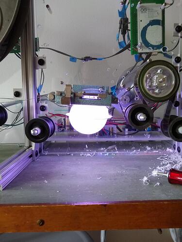
The white planet looking thing is a two-part dome. I made it by vacuum forming a half dome twice and then gluing them together. I cut a square out and attached a tin-foil tunnel (3D printed part to come) to the LED, which is mounted on the other side of the acrylic plate. Then I cut off the top to match the aperture of the gate (35mm).

Hereā€™sa link to the LED unit I bought and assembled. Would love to get some feedback on that unit. Do you think itā€™s what we need for quality results?

My next steps will be to get the camera mounted and do some tests:

  • flicker
  • maximum shutter speed
  • other? Tell me what you want me to test and Iā€™ll post the results!

CC @Greg @Andreas @quintile @Udayarangi who have been of great help in this channel

My only comment is that I would shy away from using PWM due to possible interference with a CCD camera. You might get beat frequencies. IMO analog control of the RGB channels is best. If you do resort to PWM, I would at least consider a first order filter on the output.
https://www.youtube.com/watch?v=LQDS6z-90sE
Just my 2 cents.

@matthewepler That is a really cool integrating sphere - I would love to see/know more about the vacuforming process you used. Iā€™m also curious about what the edge-to-edge falloff looks like with it (if itā€™s even detectable!).

Iā€™d echo @Gregā€™s concern about interference, depending on the imager and integration time, but there are a lot of variables. I didnā€™t see it on the LEDā€™s site, but itā€™d be cool to know what the response looks like when itā€™s ā€œtunedā€ to common targets like 3200K, 5500K and 6500K. It might have a sweet spot for color.

Thanks, Greg. I totally messed up and bought the wrong one, then. For some reason I had it in my head if there was constant current to the LED then we would avoid flicker. Back to the drawing board.

Can you point me in the right direction? What specs should I be looking for?

@johnarthurkelly what LED did you buy? I remember it not being RGB, but maybe it has a sibling?

Also - if anyone can explain to me like Iā€™m 5 what qualities make a good light in this situation and why, Iā€™d be very grateful. My knowledge of how PWM and power affect light quality is limited. Thanks so much!

My buddy has one of these: https://www.mayku.me/. I bought an acrylic half-dome from Canal Plastics and used that. It was really easy!

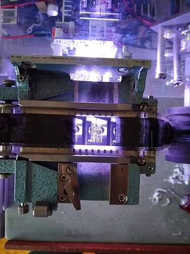
I bought the Yuji Led VTC Series High CRI COB LED - 135L 3200K model, the published curves for it looked pretty close to the original illuminant that would have been in the projector that the films in my collection would have been viewed with - that and Iā€™m pretty sure I like the response from the sensor in my build with a white balance around 3200K.

Like all machines that are involved in making, storing, manipulating and viewing pictures, the ones weā€™re building can be thought of like a system or an equation - each part/variable/factor (or illuminant, lens, medium or sensor) changes what comes out on the other side of the equals sign. To keep things as faithful or neutral as possible, Iā€™m trying to pick imaging parts that are compatible, so as to reduce conflict or disagreement in components that may manifest as image artifacts. The light is just as critical a component as the lens, camera, etc.

When all this film was designed, the lighting was assumed to be incandescent (or discharge even) from the use on set to the lab to the projector. This the lighting was pretty much all homogenous. Now, since weā€™re working with aged material in certain cases, we have to be much more careful - those old hot lights can damage or increase the rate of damage to the film. However, the sacrifice made is that in figuring out how to eliminate the heat issue, weā€™re using lights that donā€™t produce light across the spectrum in the same way as the old ones.

LEDā€™s typically are either on or off - they do not dim quite like older incandescent lights, but like older incandescents, their quality of light changes as they are dimmed. Thus there is an ā€œoptimalā€ condition in which to operate them to get the desired quality of light. If dimming is required (say you want to adjust relative brightness of a Red, Green and Blue LED separately), the most common way to go about doing that is with PWM. PWM is less desirable in our application because of the possibility of interference with the shutter on the camera - you may see banding or flickering due to the timing of the PWM and the timing of the shutter. Thatā€™s not to say it canā€™t be done - it just requires a great deal of effort to implement correctly.

Ideally (aside from dimming the light source) youā€™ll want to consider how well the light matches the film and how well it matches your sensor. Some films prints were designed to be viewed/projected with light of a particular color temperature and color sensors are designed to have a color response that is best at a particular color temperature. N.B. - Iā€™m using color temperature as an umbrella term for a lot of concepts about how the energy of the light is distributed throughout the spectrum, but 6500K or ā€œdaylightā€ etc. are familiar terms that are understandable in a broad context.

For my build in particular, I picked a light source that at full brightness wouldnā€™t meet a damage threshold for my film during a likely exposure time in the gate and then decided to set my exposure with the shutter and aperture on my lens. Since I had a light that matched the film and sensor well, very minor white balance adjustment was able to be done ā€œon-chipā€ in the camera. (Thereā€™s a wonderful set of papers that I donā€™t have the link to right now on how color records fade in many film stocks based on temperature, humidity and exposure to light.)
Matt, you might still be OK with PWM and a filter as I mentioned previously. Hereā€™s a nice little article on the topic. This is where a scope would definitely be helpful.

Matt, I think you should be ok with the path chosen for the LED driver. I think what Greg is referring to is using PWM directly to control the LEDs. Not sure about the module you are using. I couldnā€™t see the spec for the three ICs in the module, but I presume they use PWM input to control constant current output. Which is exactly what you want to avoid flicker. In essence a digital input to control analog output.

Iā€™m impressed with your design for the integrating sphere. After my first attempts with a regular diffuser Iā€™m now using an integrating sphere (of sorts) to achieve better diffusion. 3D printing didnā€™t seem like a good way to get the smooth surface required. So my current implementation is very crude: I took an old broken LED light bulb and figured the bulb was close enough to the required shape. The former base is the output opening and at a bit of an angle also the input opening. And to make it reflective instead of translucent I spray painted the whole bulb with silver rattle can paint I had lying around. Not great, but I wanted to see results first before going further down this avenue.

I think it would depend upon whether or not there is any sort of filtering on the chip itself because you would expect that controlling a constant current driver via PWM would pass that ripple on to the current driver output as well. It would be hard to know for sure without a scope or maybe just try it out and see if thereā€™s a problem.

Agreed Greg. It all depends on how the driver is turning PWM into a constant current and how constant that current really is. The IC datasheet might tell, but as you already said a scope definitely will!

John, thank you for your generous reply which I found extremely useful. I believe others will too! This kind of sharing of knowledge is exactly what these forums were built for. Thank you for sharing your knowledge and experience with us!!

What sources did you use to determine the color temperature for your kind of film/scanner?

Also, would you potentially be available for paid consulting to research options for Kinograph 2.0?

I like the hackiness of your solve! It could definitely help someone down the road in need of an emergency Kinograph repair. Keep the hacks coming!

Of course, Iā€™m happy to contribute in any way, these forums are fascinating to read and Iā€™m devouring any other resources I can find on the topics at hand. I know part of our goal here is to synthesize a huge body of R&D from a wide range of areas in engineering and film and imaging science and learning from the areas of expertise with which others approach the project is quite informative!

For my setup, I knew that the film was originally viewed with a projector that had a light source somewhere around ~3200k (itā€™s hard to say when the bulb is 50+ years old, burnt out and there are no spec sheets available) based on the design and similar projectors from the time. Some were equipped with dichroic glass to protect the film from excess heat which might ā€œcoolā€ the appearance of the light, but itā€™d still be pretty ā€œwarmā€ looking.

So I used a viewer that was around 3000K, tungsten to view the film while checking it and it looked good, it seemed to represent all the color records naturally. The sensor I chose for the scanner (best dynamic range, spatial resolution/$, shutter, frame rate considerations) had a native sweet spot at 3200K. The light source I chose also was designed for emission similar to a 3200K black body target (minus all that pesky IR).

Film of this age was kind of a mystery as far as the fading of color, I hoped it would all be okay and for the most part it has been, but I got lucky as far as storage conditions. So since 3200K was a good target for viewing from my tests and research of previous viewing conditions, I stuck with it, making sure to use components in the system that were in agreement with that choice.

As always, whiteness of light is highly subjective and the human eye is very good at adapting, so just getting it close in this case counts. Iā€™m not exactly scanning the Apollo 11 films or the latest Wally Pfister project. I also knew that there would likely be some white balance adjustment to my particular diffuser done on-chip in the camera and then further subjective color adjustment done with color-correction in post, so to speak.

Iā€™d like to correct myself. After a certain amount of cognitive dissonance, I began questioning what I wrote. I donā€™t think itā€™s a good idea to filter PWM thatā€™s intending to control a current driven device such as an LED. For brightness control of a LED, you generally must not filter the PWM, because you are using persistence of vision to obtain the relative brightness. And remember, LEDs are controlled by current, not voltage. OTOH, if you need to turn PWM into a signal that looks like a pure DAC, then filtering makes sense.

I like this approach. I think we could get 90% of what people really need out of a low-cost ā€œgood enoughā€ device whose focus is access (not preservation!) by going with a single color temperature similar to what you have in your setup.

I bought a cheap oscilloscope and will test the signal coming out of the LED I have now as was suggested in the thread. Iā€™ll also hook up the camera and see if the light source is bright enough to give us the shutter speed we want. If either of those fail, Iā€™ll be back in the market for a new lighting setup.

That was my initial goal - see whatā€™s on the film as easily (and affordably) as reasonably possible with a pretty good ā€œwhiteā€ light source. I was pleasantly surprised at how good it actually looked for my purposes, but I can see how having a tunable light source would be desirable for many folks.

If we can spec out some monochromatic LEDā€™s with desirable colors, itā€™s possible to adjust their output without PWM. Here is a good discussion on stack exchange on luminous intensity and forward current - bottom line is that with individually adjusted power supplies and some color analysis, itā€™s doable but would require a great deal more experimentation and testing. As always, these choices donā€™t happen in a vacuum and the optics and sensor choice also make a tremendous difference in the response observed in the image off the machine.

Side note: on my build I powered the Yuji LED with a current-limiting power supply that I set to the ideal forward current based on the published output and chromaticity shift curves for the LED. The process could be basically the same for an array of LEDā€™s. Also, if going a similar route to my build, these Yuji COB LEDā€™s are pretty small and could easily be combined to increase output into a diffuser. (This is likely the route Iā€™ll go when I upgrade my gate.)