I’ve made a C-mount (Raspberry Pi HQ camera) to M39 (Componon-S f2.8/50mm) extension tube for 3D printing, which some of you may find useful. Below is the link to the STL and Fusion 360 files:
For now you will have to modify the Fusion 360 file (Fusion 360 Personal is free for personal use) to get the correct length of the extension tube, or if someone can give me the full length they use for 8mm and 16mm I will update the files.
I’ve done numerous test prints until all threads worked with both the camera, the lens, and the tube itself, but you may also have to make changes to the model if you can’t get the test-print files to work.
A 3D printed tube? It’s possible but these are parts that are easily found in stores !
I have two comments:
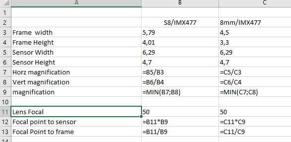
The length of your tube seems small to me. As a first approximation the size of the 8mm frame and the camera sensor are approximately equal. In this case the objective/sensor and objective/frame distances are approximately twice the focal length, 100mm in your case for the Componon.
A helicoidal ring is very useful for finely adjusting the enlargement ratio. Opinions differ but I prefer to precisely adjust the frame to the sensor without borders or perforations and therefore without the need for a subsequent crop.
Best regards,
Dominique
Thank you for replying, I followed you from Joe Herman’s and over to your own project, and eagerly read all the information posted on your google group, and much appreciate you taking the time to reply here.
I like the fact that people can just take this and 3D print, and not have to worry about buying cheap or expensive extensions.
The size is intentionally kept small, as I have no idea of how long it needs to be, and that is why I’m asking for help here. And the good thing is that I included the Fusion 360 model on Thingiverse, so anyone can open it in Fusion 360 and change the extrusion length to get the right length. I’m far from ready to take pictures, and therefore can’t determine the correct length, but if someone can tell me the length from the HQ camera’s C-mount and until the fully screwed in Componon-S lens, then I can simply adjust the model myself and update everything all uploaded files.
I can easily adjust it to your suggestion of 100mm, but does this include the length of the mount on the HQ camera and until the front of the lens, or is it from the lens’ M39 thread-stop and until the C-mount exit on the HQ camera?
John Arthur Kelly once posted this link, but I’m not sure how to use the calculator, or if it can be used to calculate the distance from the C-mount exit and until the M39 entry: Lens Calculator | Focal Length | Working Distance | Field of View
I could definitely make another version where the extension tube itself is split in in half and threaded, allowing you to adjust the length by unscrewing the two halves, but it may introduce a small wiggle/play in the threading (probably not). I could also make 2-3 version of both an 8mm and 16mm version, which I assume would be enough to cover folks who want with or without perforation/sound. But again, someone would have to give me the lengths, or wait for me to get to the point where I can grab photos myself, and adjust.
I share @dgalland 's opinion. Extension tubes and other lens-camera coupling elements are easily and cheaply found in online stores.
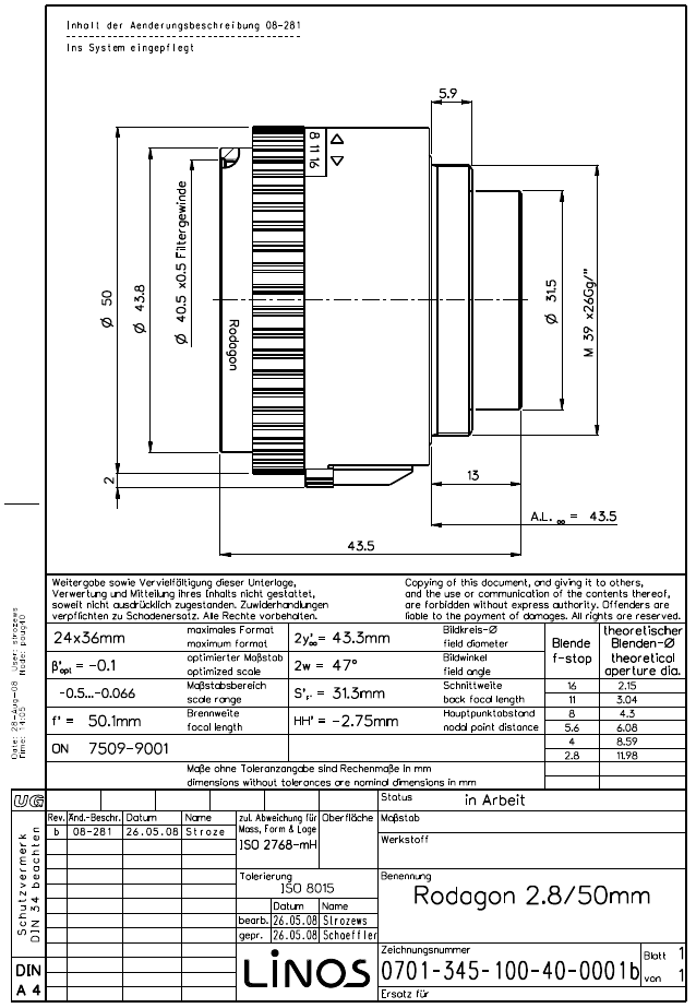
On my device I am using a Rodenstock Rodagon 50mm f 1:2.8 lens. Optically it is very similar to the Componon S.
On my device, the distance between the back of the lens (with the tube fully screwed in) and the front of the HQ camera C-mount (without the 5mm ring) is 80mm.
The distance between the Super8 film and the back of the lens: 109mm.
I would have liked to get the lens closer to the film, but with my projector it is physically impossible.
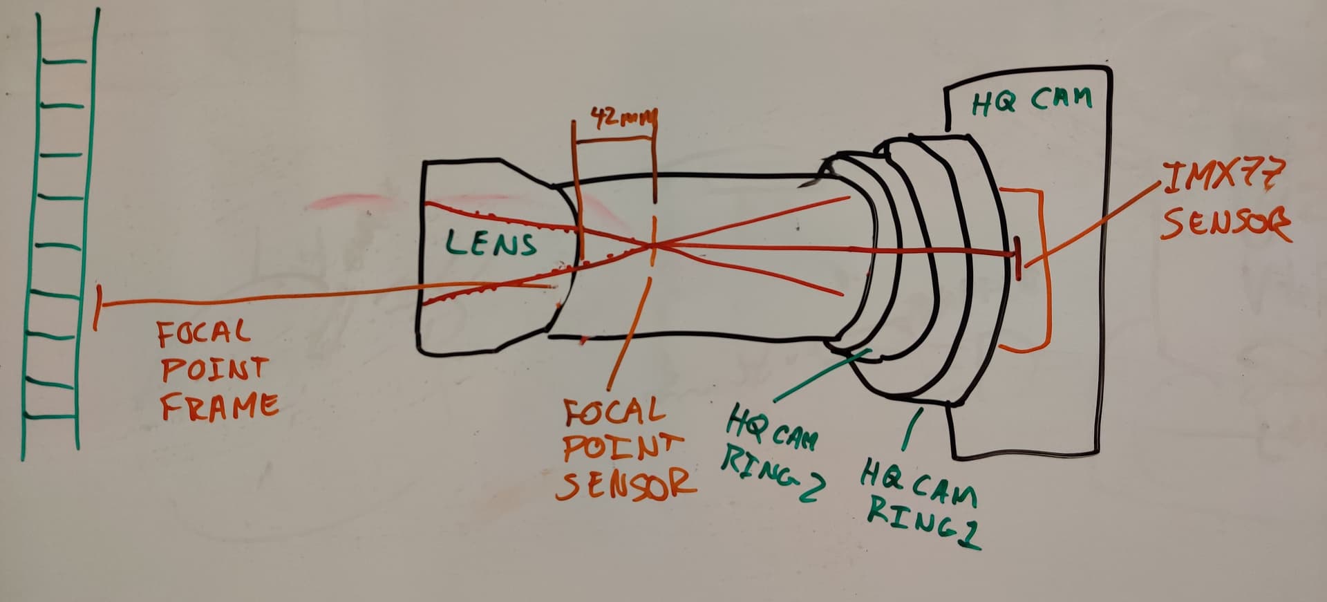
Here you can see my optical system:
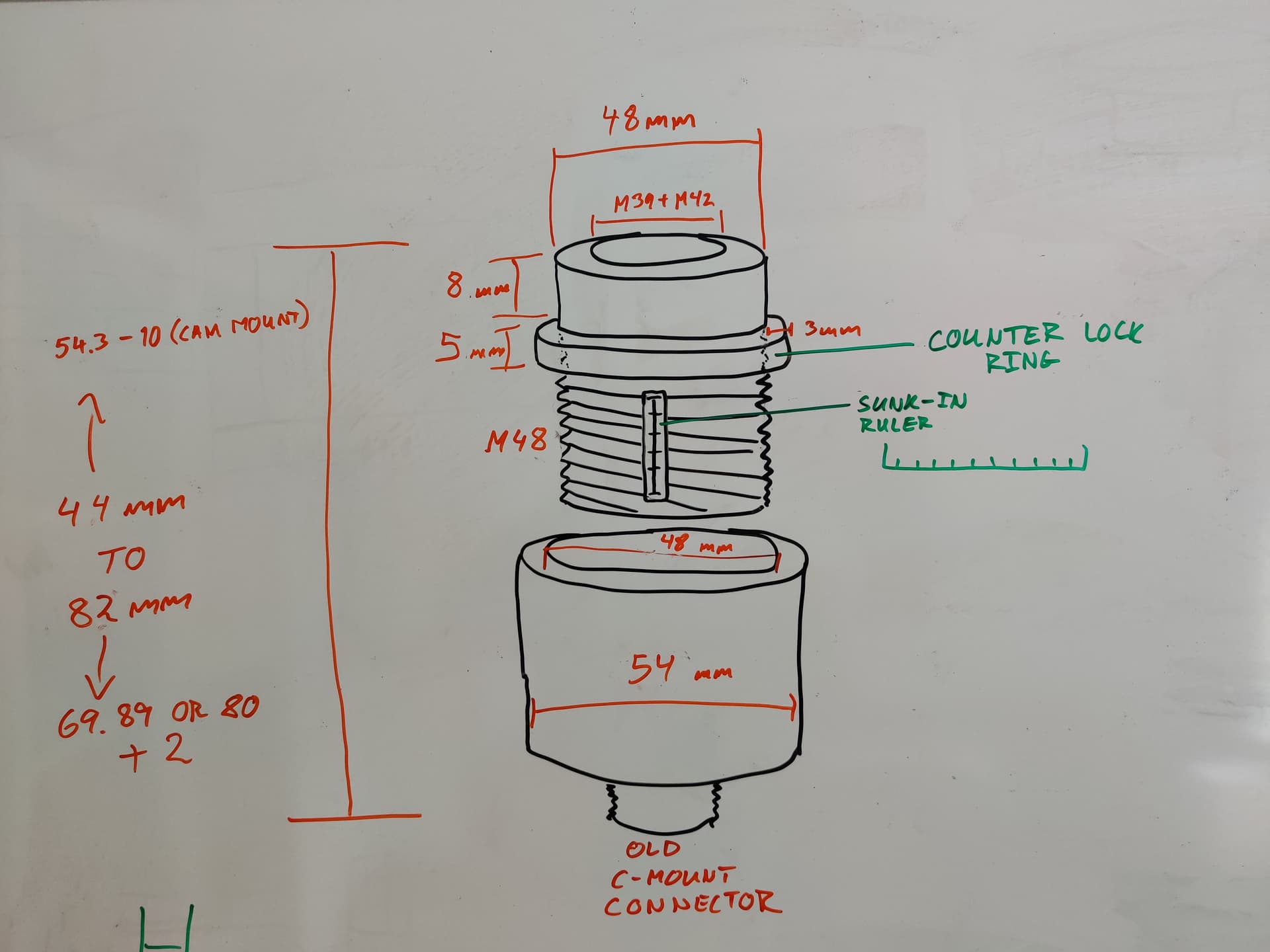
And these are the lens-camera coupling elements that I have used:
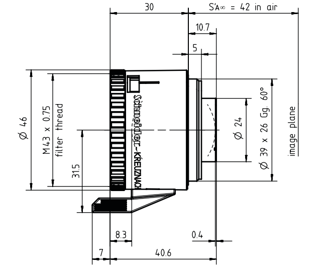
The distances are between the film, the sensor and the theoretical focal point of the lens. Add approximately 50mm and to be more precise consult the Componon diagram to have the position of the theoretical center of the object in relation to its front or rear face, 42 mm for the back focal
Note that the helical ring is to determine the length of the tube and therefore the magnification, for focusing we move the entire assembly. I highly recommend a 3-axis micrometer table but it is quite expensive. Certainly quite difficult in 3D printing because it is very sensitive and must be very stable.
Welcome to the forum, and thank you for sharing this design and ideas.
In general, I share the views that tubes are available and why complicate life with 3D printing it. Also share the view that some of these are a bit overpriced. My solution was to keep the tube in T2 (using M42 to T2 adapters), and buy the T2 extensions that are a bit more affordable.
I do not have a 3D printer, and what I have designed was printed commercially with machines that have greater capabilities than your typical home printer. With this disclosure, and my very limited 3D printing experience, I would like to offer a couple of suggestions.
A thicker wall may be needed to avoid deformation in the long tube, and to support the arm of the lens x tube length. If this is already considered in your design simply disregard, again, my hands on printing experience is limited.
A typical problem of the HQ sensor and long tube requirement, is a good stable support for the assembly, including rotating the sensor 90 degrees for best use of the pixel-to-frame ratio. I posted pictures of an aluminum bracket to mount the sensor and support the tube. If one were to take the trouble of printing the tube assembly, it would be good to design/include means for supporting it (a provision for a good bracket?).
First off, thank you all for the very helpful responses.
I’ve been on this forum since 2019 and have eagerly read all of the posts and amazing designs.
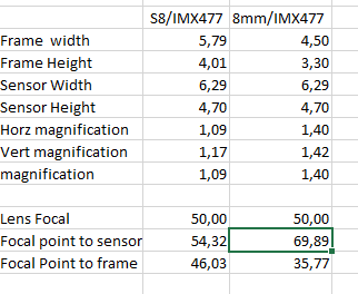
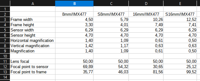
Really helpful overview of the calculation. Thank you very much. When extending to (S)16mm I get the following:
I assume these numbers would further change, when needing to capture sprocket holes and optical sound.
I don’t fully understand this, and hoping for a bit more explanation. Here’s how I understand how the calculations should be applied, please correct me if I’m wrong:
I will try to design an extension tube that will work in the same way as a helicoidal ring (if I understand the function of a helicoidal ring correctly), splitting the tube in an inner and outer tube (threaded) allowing the length to vary with X amount of cm/mm by unscrewing the two pieces from each other.
Something like this, but maybe with a custom finer thread than M48 for greater precision:
And then there would at least have to be 2 different top-tubes with different lengths, to accommodate the extension range needed, and probably also 2 additional for 16mm.
I also thought of using a 3 axis linear stage for fine positioning the camera, after seeing the many designs here, but I may start with a 3D printed design of a linear stage, and see how good it works, and if it’s terrible I will have to buy one (hopefully one can be found used, in good condition, and cheaper).
Thank you for the links to the various adapters. They are indeed cheaper than I thought. However I really like the idea of making a 3D model which everyone can use for free, and print themselves. Maybe I’m blinded by 3D printing and the expression: “With a hammer in hand, everything looks like a nail” fits me, but I think 3D printing is commonplace today, and chances of knowing someone who can 3D print for you are high. I can also make a version of the tube with a M42 thread, if you’re interested?
Interesting, as the 80mm is roughly 10mm more than the calculations above. But from the frames you posted hereMy telecine machine - #8 by Manuel_Angel it looks like you are also grabbing part of the perforations/sprocket holes, which would make sense calculation-wise (or is it actually the other way around: capturing sprocket holes requires less length?). Capturing sprocket holes is definitely something I want to allow for with the extension.
Yes I read the post a while ago, and thought it was a brilliant alternative to the “hard to get” (read: expensive) SMTPE test film.
And thank you!
All of your comments help tremendously.
My Prusa MK3S printer is from 2019 and I see them being sold rather cheaply now that the MK4 model is out, and the quality it produces is impressive. Making the “1-32 UN 2A” thread (32 threads per inch (0.794 mm pitch)) is quite possible.
I use the standard / default vertical shells in Prusa slicer (2 lines, unless sloping), and an infill between 15-20%. The thickness of the model’s circular wall is a little over 3mm and very rigid/strong (even with PLA-plastic), and still relatively light.
The nice thing about having a 3D model is that anyone can take the model and change it to their liking, meaning that extra support can “easily” be added to the model if need be, or a new model could be made to allow the tube to rest on, or squeeze around the tube.
According to the dimensions of the Componon S lens that appear earlier in this thread, the focal plane is 42 mm from the back of the lens when focusing at infinity.
Focusing at infinity means that the different light rays that penetrate the objective do so following parallel paths. The objective lenses are responsible for deflecting the rays and making them converge (that is, forming the image) 42 mm from the back.
If what we intend is to take images of an object as small as an 8 mm frame, we must move closer to the frame until the image on the sensor reaches a size that seems convenient to us.
But of course, we no longer focus on infinity. The light rays follow oblique paths and the objective lenses are not capable of deflecting them and making them converge at the same 42 mm, but rather they do so in a plane at a greater distance, the greater the distance the closer we get to the frame.
In my case I am not interested in capturing the film feed hole, but I have not been able to get closer to the frame, the construction of the projector prevents me from doing so.
If in your case, in addition to the image of the frame, you are interested in capturing the holes or the soundtrack, you will have to move the lens a little further away and, in fact, you will not need as much extension.
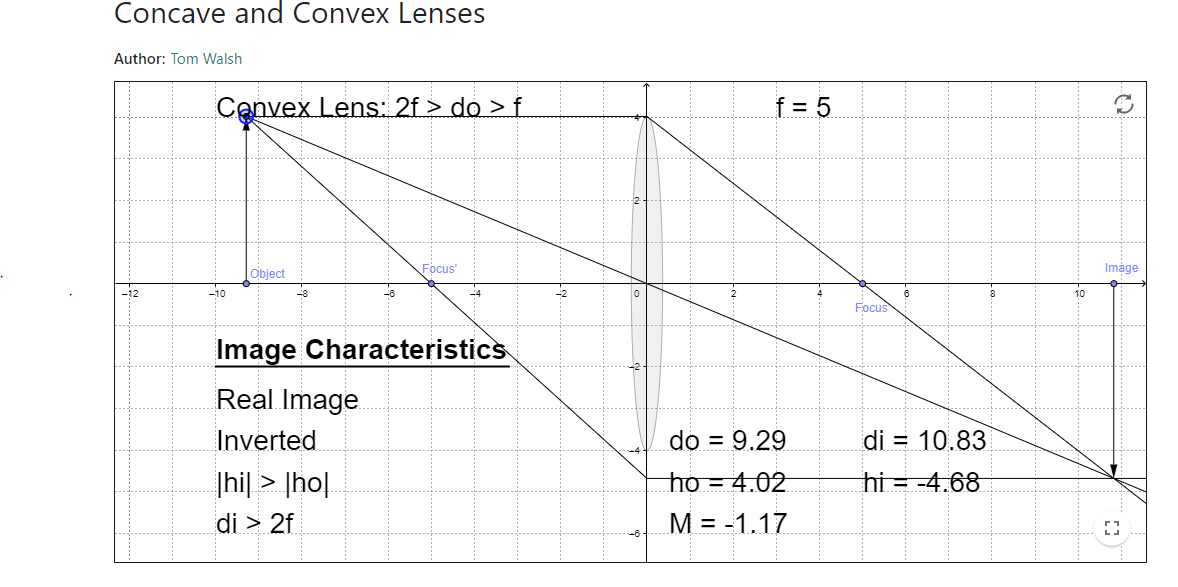
the S8 film (object) is on the left and the sensor (image) on the right (multiply by 10 the horizontal axis)
Move the object height ho and distance do to get the right height hi on the sensor.
I’ve made a new version with the possibility of extending the length of the tube:
I haven’t printed this yet, but will upload the files to the same thingiverse link as the original post.
I’ve included both an M39 (Componon-S) and M42 (Rodenstock Rodagon), but the current extension only covers the range: minimum: 42 mm and out to 62 mm. Another top extension will be made to cover a longer range, once I understand the math behind the calculation.
I also haven’t printed this yet, but planning on doing it this weekend to test if it prints and fits well.
The ruler on the extension can be painted with white nail polish or similar to make it easier to see.
The thread of the Rodenstock Rodagon 50 mm f 1:2.8 lens is M39 as in the case of the Componon S lens.
The M42 thread is widely used. It was the mount used by the old Pentax reflex cameras. For this reason there are many accessories that use this type of thread.
To use these accessories with lenses such as the Componon or Rodagon, it is necessary to use M39 - M42 adapter ring
Printed the new version and I’m pretty happy with the outcome, but of course this needs to be tested once I have a more complete setup, and the correct length calculated.
3D printable files, and 3D models are available through the thingiverse link, and here’s a short intro video: