First off, thank you all for the very helpful responses.
I’ve been on this forum since 2019 and have eagerly read all of the posts and amazing designs.
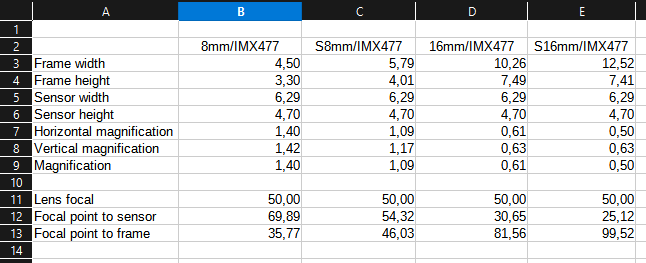
Really helpful overview of the calculation. Thank you very much. When extending to (S)16mm I get the following:
I assume these numbers would further change, when needing to capture sprocket holes and optical sound.
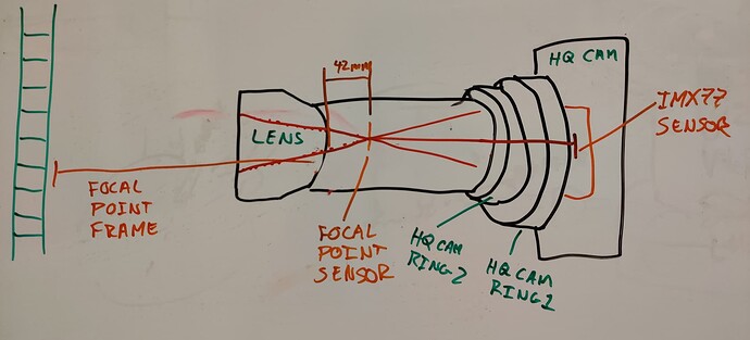
I don’t fully understand this, and hoping for a bit more explanation. Here’s how I understand how the calculations should be applied, please correct me if I’m wrong:
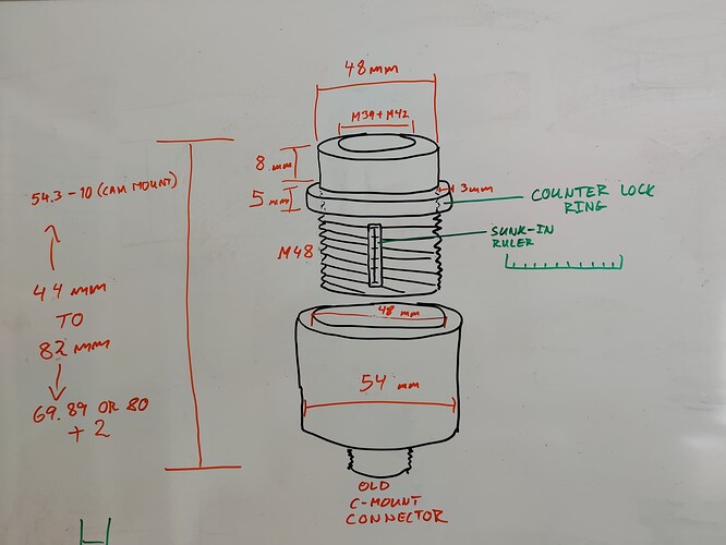
I will try to design an extension tube that will work in the same way as a helicoidal ring (if I understand the function of a helicoidal ring correctly), splitting the tube in an inner and outer tube (threaded) allowing the length to vary with X amount of cm/mm by unscrewing the two pieces from each other.
Something like this, but maybe with a custom finer thread than M48 for greater precision:
And then there would at least have to be 2 different top-tubes with different lengths, to accommodate the extension range needed, and probably also 2 additional for 16mm.
I also thought of using a 3 axis linear stage for fine positioning the camera, after seeing the many designs here, but I may start with a 3D printed design of a linear stage, and see how good it works, and if it’s terrible I will have to buy one (hopefully one can be found used, in good condition, and cheaper).
Thank you for the links to the various adapters. They are indeed cheaper than I thought. However I really like the idea of making a 3D model which everyone can use for free, and print themselves. Maybe I’m blinded by 3D printing and the expression: “With a hammer in hand, everything looks like a nail” fits me, but I think 3D printing is commonplace today, and chances of knowing someone who can 3D print for you are high. I can also make a version of the tube with a M42 thread, if you’re interested?
Interesting, as the 80mm is roughly 10mm more than the calculations above. But from the frames you posted hereMy telecine machine - #8 by Manuel_Angel it looks like you are also grabbing part of the perforations/sprocket holes, which would make sense calculation-wise (or is it actually the other way around: capturing sprocket holes requires less length?). Capturing sprocket holes is definitely something I want to allow for with the extension.
Yes I read the post a while ago, and thought it was a brilliant alternative to the “hard to get” (read: expensive) SMTPE test film.
And thank you!
All of your comments help tremendously.
My Prusa MK3S printer is from 2019 and I see them being sold rather cheaply now that the MK4 model is out, and the quality it produces is impressive. Making the “1-32 UN 2A” thread (32 threads per inch (0.794 mm pitch)) is quite possible.
I use the standard / default vertical shells in Prusa slicer (2 lines, unless sloping), and an infill between 15-20%. The thickness of the model’s circular wall is a little over 3mm and very rigid/strong (even with PLA-plastic), and still relatively light.
The nice thing about having a 3D model is that anyone can take the model and change it to their liking, meaning that extra support can “easily” be added to the model if need be, or a new model could be made to allow the tube to rest on, or squeeze around the tube.
BR
Chris


