I’ve got many years of experience working with film so I have a good sense of when the tension is too high or too low. But as I get further into the code for the 70mm scanner, I’m thinking I’d like to find a way to quantify this so I can measure the tensions in different scenarios.
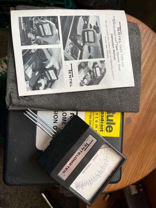
For video and audio tape you use a Tentelometer for this, and we do have one, though I’ve never used it on film. I suppose it would work but the scale only goes up to 500g and I think the tension on film can probably go higher than that in some cases.
I tried the Tentelometer we have here but because it’s engineered for videotape (which is incredibly thin), just sliding film in there shows a reading, before you apply any tension to the film. I’d love to find a similar device that can handle thicker material.
I used a tension gig to calibrate the sensors in the project, which are swinging pots. Then the swinging pots do the job. If I understand correctly you are looking for something to move around the path.
Here is a tool that may do the job for up to 50mm ribbon.
A 3 roller design as shown in the tension meter in the link, where the center roller is mounted in a load cell should do what you are looking for. Although one limitation would be that the range of the sensor would be limited by the range of the load cell.
Last option, there is always an arm, a pot, and a spring. The center roller (instead of a loadcell) may be the arm tensioned by a spring and measured by a pot.
Thanks. That gives me a little more to look for. I wonder i one of those Schmidt tools could be modified to take a wider film (Since I’d want to test 70mm).
And is obviously unsuitable for film since it’s meant to test very thin film like video and audio tape. But the shafts are long enough that you can actually fit it over the width of a 70mm strip of film.
I’ll keep looking I guess. I’m not looking for something permanently mounted to the scanner, really this is just for testing the tension while I dial things in. Right now I get some feedback from the motors as to the percentage of max torque on the motors (which gives me a number I can adjust if need be), but I want to corollate that with actual tension values on the film in ounces or grams, the standard measure of these things.
so of course this made me dig through the closet where we have a bunch of old 70mm plastic rollers from a projector payout head. I think I could make something pretty easily with a cheap digital force gauge. Basically an aluminum plate with two holes for left and right rollers and a spot for a middle roller that can move forward and backward. Maybe spring loaded to hold it in the up position, and then the force pushes it down. The base of this roller would touch the force gauge, so any downward pressure would register.
I even have an old Canon Super 8 camera handle that’s removable and could be mounted to the bottom to give it a nice grip.
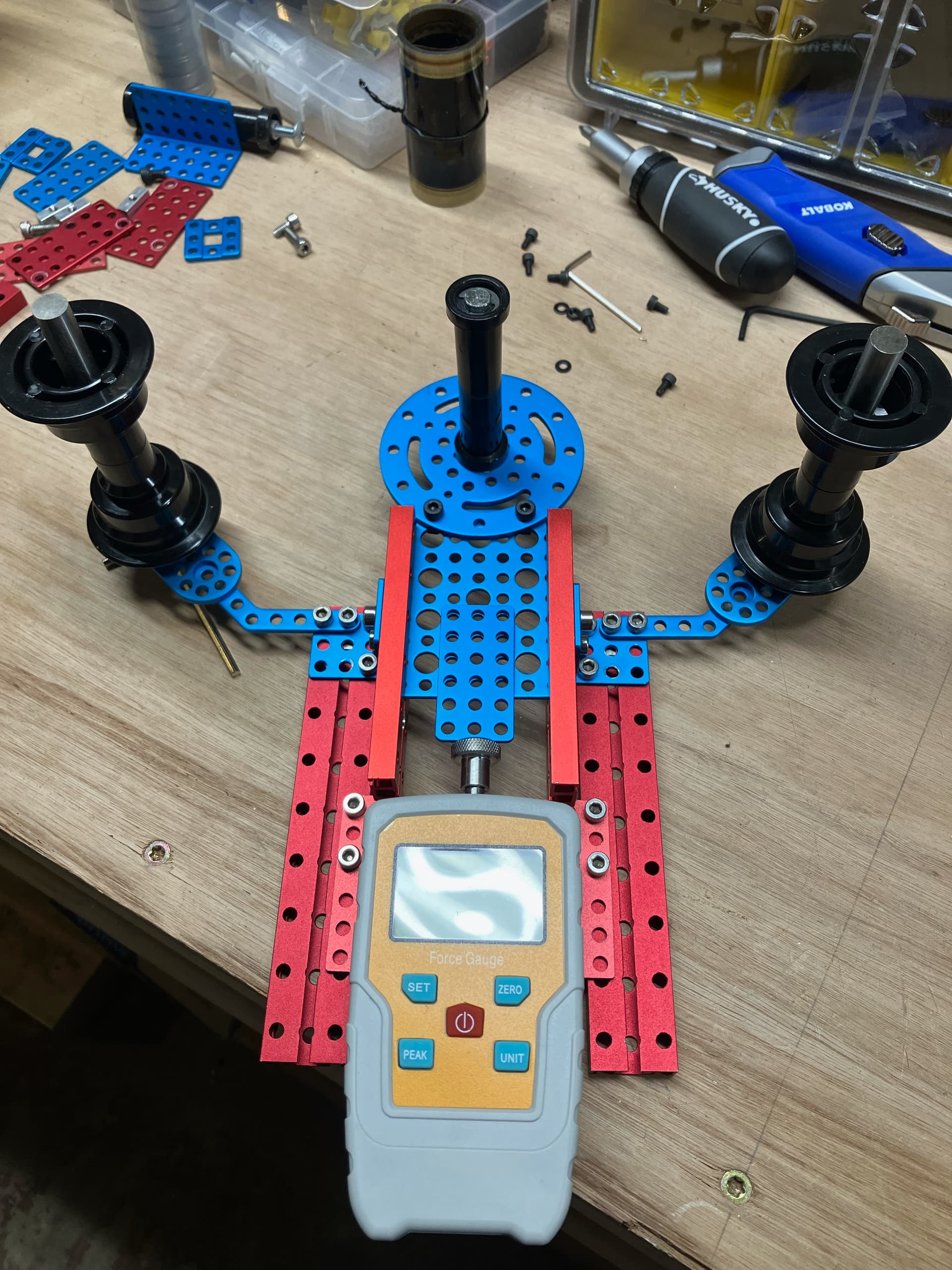
Well it’s certainly colorful. I had some extra stuff in a bin at the office from when I was first prototyping things on Sasquatch a few years ago and was able to piece together most of a tension gauge last night. I still need to install the bearings for the two side rollers, and I need to install some springs on the blue plate that holds the central roller - a pair of extension springs on each side of that plate, underneath it, which both pull it towards and away from the force gauge. that way it should be at a kind of equilibrium. I only need a small amount of movement for this so I think it’ll work. Springs arrive today and I’ll see if I can wrap this up tonight.
My only concern is that it may be too wide as-is, but I think I can adjust for that by bringing the side arms in a bit if need be. shouldn’t be too much of a modification to do that.
I assume this is for getting a number and not for application in a scanner itself. Since the load cell / force gage doesn’t move much, you can just calculate (trig) the actual tension, versus what the load cell is measuring. Looking at your set up, actual tension may be 3-4X what the load cell indicates.
The problem with using a load cell is the tiny deflections and also converting those signals into something useful for the uC. An arm with a potentiometer is easier to implement and allows more mechanical movement. The problem with using a potentiometer is constant movement over a small range will likely cause wear. The question might be, does tension matter as long as it remains in a specified range?
All high end scanners I’ve seen use either a load cell (Kinetta), or a swing-arm on a potentiometer or similar. Some have a round disc with two rollers the film goes around, and that entire disc rotates, while the rollers rotate on that (our Imagica and Northlight scanners did this), and that uses a potentiometer, I believe.
When we had the deck plate for the scanner cut on the CNC we didn’t include a space for a roller necessary for a potentiometer, and because we’re handling multiple gauges, some very non-standard that we haven’t even seen in person yet, we can’t have a roller that works for everything. It has to go over a 70mm PTR in our case. That’s a bit clunky to try to work a potentiometer onto. A load cell might work, or maybe one of the rotating disc setups, but I don’t think it’s necessary with our setup.
To answer your question - this wacky little device is to get a relative sense of the tension when calibrating the machine. I have been scanning film long enough that I can tell when the tension is in the right range. So the idea here is to get a measurement when we have the tension where we want it, then to get measurements at different parts of the wind, correlate that with the feedback from the motor, and make sure we’re not too loose or too tight. Once we have that at in a consistent range across the reel (since both feed and takeup motors provide tension and that changes depending on how much film is on each end and on which gauge you’re using), we can use that information if we need to make things more or less taut, relative to that baseline for that gauge of film.