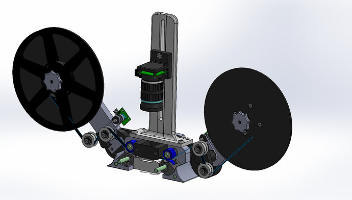
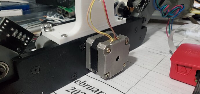
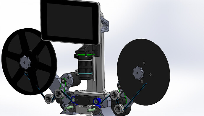
I think the primary design is done, even got a few parts printing. I wanted to know what everyones thought are? I think I can upload the actual model (maybe) but what format can everyone view it in, Solidworks, Parasolid, IGS, STEP?
What film size is the machine for?
Currently just 8mm, but should be able to do others with the change of a couple of parts,
Me and my father are just getting started with our research for super8 scanning, but I personally would prefer STEP files, seeing as it is a standard format for model exchange? Plus, it being fairly open, its pretty much guaranteed to be readable in almost every software.
Design looks great btw. Thank you for sharing.
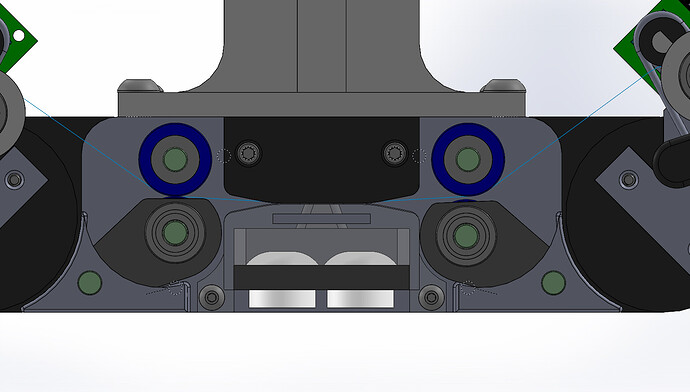
Also, are you planning to use PTR rollers? (marked in blue?)
FilmScanRPi.zip (3.9 MB)
Here is the compressed zip file with the complete unit in the STEP format.
While I am not sure exactly what you mean by PTR rollers (printer maybe), they are from McMaster-Carr. While the upper rollers are driven on both sides, the lower rolls are under pressure with springs, “Stacked Wave Disc Springs” again from McMaster-Carr (not in model). While most of the films that I have are in relatively good shape, there is one or two that are missing the holes, and I was worried about making those any worse. So, with this unit the film is designed to be driven by (what I am calling) pinch rollers.
Once I get some actual testing done, I plan on adding a mount for the Raspberry Pi and a 7" Touch Screen mounted to the unit. It currently has the 16mm Raspberry Pi Lens with the camera and am still unsure how that is going to work out.
Please let me know what you (or anyone) think, possible issues that you see, or even improvements that you would make, for that matter any criticism is appreciated!
First of all, I must say the design looks great and I’m looking forward to seeing it built!
One thing that caught my eye is that you seem to want to use the 16mm lens for the Pi HQ Camera. I haven’t actually tried that lens for film scanning purposes, but I think the preferred method is to use an enlarger lens with extension tubes to achieve the kind of magnification we need. Myself and others have shown some of their lens setups in this thread. Obviously, this needs a bit more space and probably also weighs a little more, but it works very well and the results look great. I think your design is also well suited to accommodating such a lens setup.
Design looks great, look forward to see the results.
I have the same observation as @jankaiser in regards to the film-center to mounting-plane, you may want to have additional space so you can accommodate a lens with a larger diameter, or for that matter, a future camera with a larger sensor. The additional space of the vertical column can be traded by larger camera mount.
Along the same lines, keep in mind that the focus is extremely critical.
To that effect, if the center of the sensor is not perfectly aligned with the film center, it can result in soft edges. Additional space in the column may also provide room for a focusing rail slider (built or bought).
Question: are the PCBs near the arms optical encoders? curious as to what kind of resolution you need for precise sprocket alignment.
The lens is just what I already have and will try to see if it will work, although I (admittedly) haven’t researched it as much as I probably should have. That being said this does bring up a very valuable thing that I will change this evening. I will move the camera mounting arm all the way back, to make room for a different lens setup as well as make it adjustable to aid with alignment should it be needed. I will post the updated model as soon as I have that done.
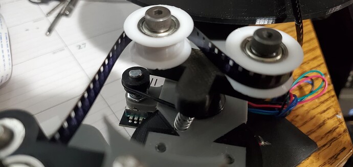
Yes those are encoders. I am not doing any sprocket alignment with this unit. The idler rollers on each arm are actually only for maintaining film tension. The spools are driven by stepper motors and the idler assembly has a spring (extremely lightweight spring).
Thank you guys for the feed back! As the parts are printed, I will post some assembly pictures as it builds up.
Thank you for the information. I’m doing a simple build based on steppers directly driving the spools. Haven’t really started, would be first doing a test setup to better understand the capabilities/limitations. Plan to do it with the raspberry pico, and will share the results in the forum.
The forum has some information on the results of lenses, particularly those used with the raspberry pi HQ camera. I’ve recently got an HQ, and tested it with the same lens I used with the DSLR, which is a Schneider Componnon 50mm/2.8. Also used have a Nikkor EL 50mm/2.8. Both provide really good results, with the Schneider providing a bit better sharpness away from the center. This site has been shared before and provides a really good reference comparison between some typical enlarger lenses.
PS. This is a good thread on the elements to mount the lenses to a C/CS.
FilmScanRPi .zip (3.9 MB)
Sorry for the delay, my refrigerator, had a mind of its own, but fixed now (gotta keep the drinks cold)!
Here is the latest model. It now has the capability to have a lens up to ~75.5mm in diameter. Hopefully that will cover whatever lens will end up being used.
I am hoping to get both, organized enough and far enough, that I will start a GitHub Project for this. After much trial and not so successful results (primarily Mechanical Design, but also the quality of the end result), I minimally have a pretty good idea of what I am going to do on the software side of things. I am combining several different projects that are currently on GitHub, as well as a few that are out there. Much like Alexamder/RPiTelecine project, I am planning on simplifying the electronics, which changes a bit on the software side of things, but the basics are pretty much it. Utilizing OpenCV to locate the perforation to determine where the desire image should be, which helped (in the past) with frame stabilization. Although with that project it despiritly needed a GUI, to make more user friendly.
There are a lot of projects that are influencing the end package that I am after, but let me know what you think!
FYI the printing is coming along and should hopefully have all the initial parts this coming week. Will post pictures when I get that far.
Thanks for sharing the drawing. A couple of additional comments/questions.
Do you have enough space for the light? Many builds are using direct light with a diffuser, and that is actually how I started, but later I moved to using an oversized ping-pong ball as integrating sphere and had much better results and even light. I haven’t gotten into 3D printing (that’s what I used the ping-pong) but Kinograph did a nice 3D printed sphere (much larger for 35mm).
The other comment is how easy/difficult is going to be to thread the film through the gate and surrounding rollers.
Very nice work, looking forward to see your results.
Thank you for sharing your design with the community. It’s a beauty! I appreciate the effort it takes to come up with this and it’s so nice to see the generosity that started this forum continue through your work. Godspeed and please keep us updated!
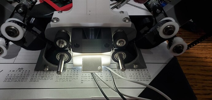
To answer your questions, the 2 white dome things in the middle is currently what I am using as my light source. They are actually Automotive LED Utility Lights made by Hopkins #C1534BCK, that I got at Autozone. My initial testing utilizing my cell phone, the brightness was acceptable. Although I believe that the housing is sized enough to put in a cylindrical bulb, much like the old automotive dome lights.
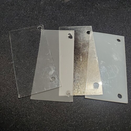
The slot above the lights is where my diffusers go. I had an old Flat Bed Scanner that had the capabilities of scanning slides, laying around, that had long since died and wasn’t supported anymore from HP. I stole the Diffuser material from it and cut it down to fit into that slot. It consist of (from light source side to scan side) a 1.5mm layer of white translucent material (looks almost like nylon), followed by a lenticular lens, then a thin layer of translucent material, and finally a thin layer of clear plexyglass.
In the picture you can see that the left pinch roll is tight to the left drive roll. On the right the pinch roll is in the lowered position. The lower pinch rolls have a spring that is not shown that keeps the rolls up. Looking at the original image, the pinch rolls have longer pins, which allow for easy opening on the rolls to both insert and remove the film. The Gate and Light Box, things are a little tighter. There is a groove that is supposed to keep the film in place, but the Light Box only has this a lip on the back. So hopefully it will come out fairly easy, as well as going in. Although I won’t know for sure until later this week, when those parts come off the printer and can be mounted.
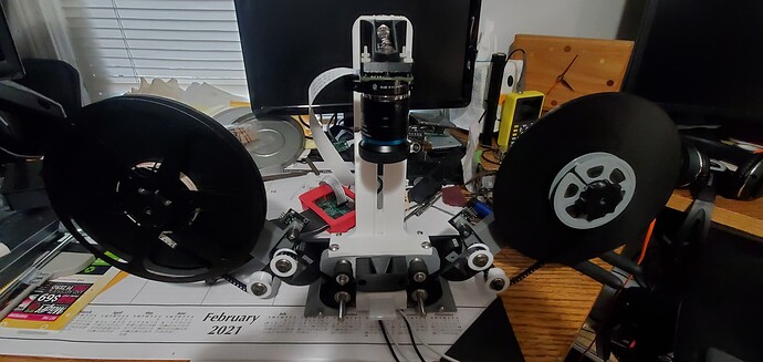
Well it went together pretty good. There are a few issues that I have to address, but nothing fatal. Sorry for the lack of lighting in the images.
Need to change the motor mount. It’s a little hard to adjust the belt tension from the inside, once assembled.
I found that the encoders that I planned on using for the Tensioning of the film, which have the Click Position in the rotation, are too stiff. If I increase the spring capacity to overcome the encoder clicks, it seems like it is too much tension on the film. Since I have some extra encoders, I may just take one apart and see if I can remove the click position thing.
While I have some extra diffuser material hanging out, the light box seems to be working.
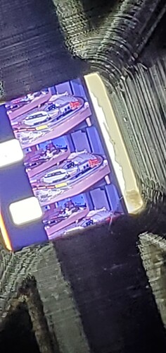
Even though I need to clean the edges of the opening of the light box, the generic cell phone image doesn’t look too bad.
I will make the modifications to the Model and repost it. Once again if you have any ideas for improvements or see any issues, please let me know, it is much appreciated!!!
Congratulations! It’s looking really great. Happy to give any feedback you are looking for. Having the models will help me get a better since of what’s going on. Great work! Thanks for sharing it with us.
Sorry for the delay, I will have the updated ones by the end of the weekend, I am adding a bracket for the Raspberry 7" Display and for the Raspberry itself. Also working on a simple circuit board to plug into the Raspberry that accepts the Easy Drivers for the Stepper Motors, as well as simple plug-ins for the encoders, which should make the electrical side a breeze.
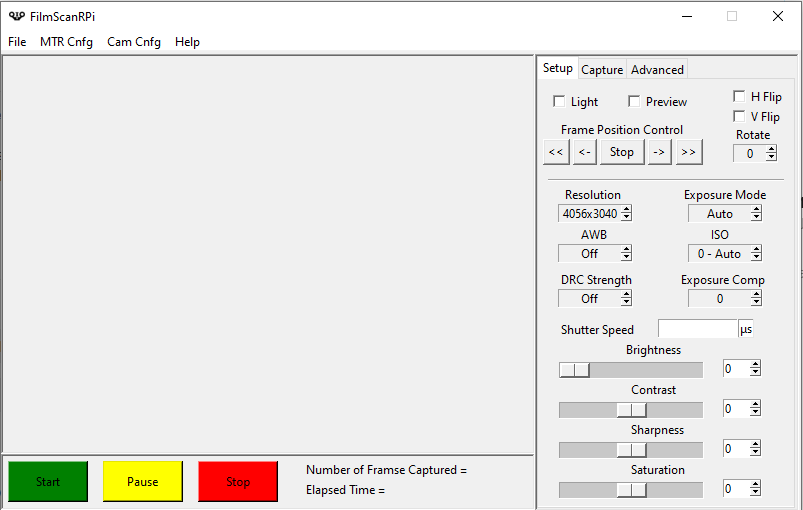
I have also been working on the GUI / Graphical User Interface. I think I might be off to a good start on it?
Well know I have to figure out how to upload the model for everyone. Now the size of the Zip file is too large. So, if someone has an idea on how to get around the 4Mb file size limit, let me know, or message me and I can send it to you.
The only thing that I haven’t figured out yet, is the best way to mount the Pi yet. So that should be coming soon as well. I am thinking at this point there isn’t much of anything that I haven’t printed more than once. Oh well, good learning experience and keeps me somewhat out of trouble.
I also had to go with different encoders, a bit more expensive, but not enough to break the bank. I was also able to correct the other issues as well. Once those parts finish up printing, and are ready to be tested I will follow up.
For programming and design tips you can look at my yart project. In which language do you plan to make your application?
I’ve seen a little bit of yours, and your software looks nice from what I have seen from the screen shots.
I am planning on a slightly different approach, than yours. I am planning on this being stand alone, and at least initially, it will store all the images on a USB hard drive which can be processed later, either by the Pi or by PC (haven’t determined that 100% yet).
The software is done in Python, utilizing tkinter for the GUI. Problem is, I did Visual Basic programming 20+ years ago, so I am learning as I go right now, incorporating features from a few other projects. If you want what I have so far I can send it on to you if you want, it has changed a little bit since my screen shot.
Yes my application is PC/PI client-server but a 100% Pi stand-alone application with a GUI and storage on USB disk is probably possible (Pi4 may be needed for better USB throughput).
I just wanted to draw your attention to the fact that efficient programming of the PiCamera + Stepper is quite tricky and that the design of the application has to be well thought out, especially if you add a GUI.
On the github of my project there is a “design” document that explains the problem. Also watch out for changes on Picamera python library (see posts on this subject)
