My 8mm/Super8 Scanner build (in progress, LED help)

Hello all!
I am building an 8mm/S8mm scanner and thought I’d share my progress so far, and perhaps ask for some advice on LEDs, as I think that’s where one of my problems lay.

So here she is.
Sturdy piece of wood, some metal parts from BnQ, bits salvaged off an 8mm/S8 editor.
Pi4B, Pi HQCam V3, Pi Microscope cam.

Here are three pictures, the first is the ‘goal’ for me. It’s a scan from my Plustek 8200i slide scanner. I’ve scanned part of an 8mm reel on it before and was very very happy with the results, they were as good as the pro’s scans which I’ve previously paid to have done:

This second picture is direct off the Pi4 that I’ve built just quickly snapped with piccam2. It doesn’t look good. The blues are blown out…there’s blotchy artifacts all over it, looks like a water colour. Not what I’m going for…was worried :face_with_head_bandage:

But, here’s picture 3 and this instead saved as raw with a few adjustments in piccam2 to desaturate it somewhat before it was saved…


I breathed a sigh of relief, as clearly it was the jpg compression which was borking the quality, much happier with that…but the colour issues remain.
Am I right in thinking it’s my LED (which is temporarily powered by a 9V battery whilst I work out what to do). I was reading a very extensive thread on here about blue wavelength light and LEDS…it seems that might be the culprit here? Any help or advice very much appreciated it. Maybe I should take the plustek 8200i to pieces and find out what light it’s using?? haha.

Welcome @Rowan!

Well, as you have discovered, you have a little more headroom if you scan in raw than in .jpg. The .jpg which is delivered by picamera2 is basically “developed” by the underlying libcamera. How this is handled is specified in a tuning file. Now, the standard tuning file has some deficits - there is an alternative tuning file which features less contrast and less saturated colors (“imx477_scientific.json”). This has been discussed elsewhere on this forum as well as the Raspberry Pi foundations camera forum.

In any case, the color science these tuning files are based on is a illumination spectrum close to normal daylight. Sadly, no LED comes really close to such a spectrum. An indication on how close a specific LED comes to daylight illumination is the CRI-index of the LED in question. The closer to 100, the better. A 95 or 98 value should be ok for practical purposes.

If you work in raw, you have to “develop” the raw by yourself - which can get challenging. But since you have a larger bit-depth available in raw (10 or 12 bit/channel) than in .jpgs (8bit/channel), you can recover more image content. That’s actually the major difference - besides the somewhat slower scan and larger disk space requirements for a single image, compared to .jpg. Note that any .jpg-compression artifacts are practically not noticeable once you set the .jpg-quality above 90. I am using 95 in my setup, to give you a reference.

If you want to do some further experiments, I would suggest to increase jpg-quality to 95% and use the “imx477_scientific.json” tuning file instead of the standard one. Another experiment worth to try would be to use a LED with a CRI of at least 95 instead of the one you are currently using.

One note on the idea of using your scanner illumination - most of these illuminations used in scanners are usually very far off from the standard daylight illumination. But the scanner’s software takes this into account, by using an appropriate color processing pipeline. If you use such an illumination with the tuning files available for the HQ sensor (based on daylight illumination), you probably will not get a satisfying result. (That is just a guess - I do not know the specific illumination build into the plustek scanner.)

One final note: you could try using manual white-balance mode to improve the scan as well. The AWB-algorithm of libcamera is not too great; setting the red and blue gain manually should also improve your scan results.

2 Likes

This is really good information, thank you so much cpixip!
I’m glad to hear you can turn the quality up on the jpg, that will be my next mission, along with finding one of these fabled CRI 95+ LEDs!

If you’re interested here’s the video of the scan I did using the 8200i! It involved basically feeding the reel through the scanner, scanning about 4 frames at a time, then doing a bunch of cropping and leveling after the fact - I think it took about a day to scan just that short piece of footage, then a lot longer to do the ‘post processing’ not at all practical for 400ft!!! but I only needed that short piece of footage the rest wasn’t of Scilly so saved me a little bit of money by scanning it myself using such a time-consuming method! There’s a little warping toward the end because it didn’t have a gate, but perfectly acceptable otherwise imo. Bit of a shame it was filmed on a rough sea!!
1951, Round Island Lighthouse, Scillonian (I), HMS Scorpion D64 and HMS Worcester D96 - YouTube

Thank you again for your reply!

I must admit I’m a little confused I’ve been researching LEDS and it looks like you can buy 5 LEDs of the 95CRI+ variety for like £150, but then you see stuff like this on ebay
PAUTIX COB LED Strip Warm White 3000K, 5M 2400LEDs 24V CRI90+ Dimmable Bright | eBay
and that’s got 2400 LEDS??? for £30.
I can’t seem to find any nice small LED panels with the right kind of LEDS on them already. Super frustrating.

what about using an actual real LED light bulb?!?! :melting_face:

@Rowan welcome to the forum.

Sharing this link (US based company) that seem to have a good selection of known-brand LEDs at somewhat reasonable price. I have not ordered from them, so take it as an internet find.

When playing with the LED, I started with folding a high CRI LED strip, and then moved into designing my own PCB with a sourced LED.

(the rulers on the mat are inches).

@cpixip suggestions are spot on, specially in regards to his work with the color of the HQ sensor.

I have considered designing a smaller PCB than what is shown in the picture at the bottom, and make these available. But the form factor of each design varies so much that it may not be practical, and the cost would be much more than what the link above provides.

1 Like

Well, there are some whitelight-LEDs mentioned in various threads in this forum which are suitable. The price range is substantial, from a few €/$ up to hundreds…

I am using an Osram Oslan SSL 80 type (because I had this in my spare box) which typically features a CRI of 96. The data sheet guarantees a CRI > 90. Here’s the spectral distribution of the type of LED (the solid curve):

You see a small peak in the blue region (around 450 nm) - this is actually the signature of the real LED; the rest of the spectrum is created by flourescent material embedded in the LED - and this is where the science/magic of the manufacturer comes into play. But basically, that’s how a whitelight-LED’s spectrum typically looks like.

This spectrum is not really a daylight spectrum - for which your camera’s color science is normally tuned to. Ideally, one should take this spectrum into account when creating the color science for a scanner. However, from my experience, the difference are negligable for high CRI LEDs.

There’s another point to remember here: again from my experience, the colors of old amateur footage typical need a color correction anyway, in postproduction. There are several reasons for this. First of all, Super-8 material had only two color temperatures available at the time of filming: either daylight or Tungsten. But “daylight” is a broad term, ranging in color temperature from 4000K to over 8000K typically. So you were typically already off color-wise when recording the footage.

Additionally, some film stock will have faded over the years, making it even more challenging to obtain colors close to the original scene. @PM490 has some nice examples here on the forum of how far you can recover faded memories.

My guess on why you got these initial weird results with the HQ camera (too blue, too saturated) is the following:

  • your LED has a much stronger blue peak than one of the LEDs with a higher CRI. This creates the blueish tint. One can counter this with reducing the blue gain (no AWB!). But the better approach is to improve the illumination
  • the colors of you .jpg-scan are too saturated. This is probably caused by a deliberate choice of the Raspberry Pi team to have vivid colors delivered in the standard configuration. This is backed-in into the standard tuning file; especially the contrast curve used in the standard tuning file pushes colors. You can counter this by using the “imx477_scientific.json” mentioned earlier. This tuning file includes also a few other modification you want to have when scanning film stock, most noteably, the apdative lens shading algorithm is deactivated as well as some other automatic algorithms which lead to flickering in your scanning results.
2 Likes

Thank you for such awesome info - I’m really looking forward to trying out the tuning file and see how things changes, but as you say important to start with good lighting.
As perhaps luck would have it I went to the charity shop today and they had a slide viewer (Jessops SV8D) for sale for 50p claiming ‘daylight adjusted’. Dubious perhaps, but I tore it to shreds and salvaged the light which appears to be a filament tube and PCB out of it to see what might happen.


Still getting blue halos, but will experiment a little more

– what specifically to you mean by “blue halos”?

Let’s go through a little process of adjusting your color science.

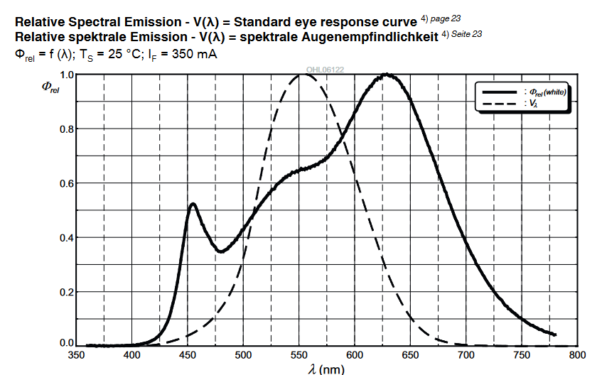
But before that, one note of caution: if you want to get good scan results, you should refrain from using a lightsource of unknow origin. There are all sorts of different illumination source out in the wild, very often with very weird spectra. Google a little bit for spectra of flourescent lightsources (or other sources you might be interested in) and then google “spectrum D65” to see one of the spectral distribution your HQ camera is tuned too (in fact, practically every other color camera as well). You should notice some differences…

Any manufacturer of a scanner can use - within limits - cheaper illumination sources, as long as he adapts the color science of his processing pipeline accordingly. In a way, manually developing a raw image so that “it looks good on the screen” is doing a similar thing. But such an esthetic-based manual approach is nowhere close to the real thing, an exact color sciene result.

For most of us building a film scanner with available hardware, we are limited by the camera we opted to purchase for the project. Most of the time, this specific camera comes with software which will deliver an sRGB-output, a .jpg for example. The color calibration for this is backed into the software delivered with the camera and can usually not be changed by the user. There is a simple reason for this: color calibration is difficult. And of course, most manufacturer-based calibrations are based on spectra like the D65 one - i.e. “daylight”, not any exotic light source. So: get your light source close to such a spectra, and things should improve colorwise.

The Raspberry Pi foundation’s choice of the libcamera image processing pipeline opens up for the first time the possibility to do your own color science. That’s a great step forward, but, as already noted, the standard file describing this processing for the HQ camera has some deficits.

There are threads on this forum with more detail about this, but the variation of the CCM-matrices with respect to color temperature found in the original tuning file indicate that it is not trivial to capture good quality calibration images. Another rather annoying thing is a backed-in lens shading correction. This shading correction is only valid for a specific lens - and it is unknown which lens this is. The result of this missmatch might be a slight vignetting of your image. It really depends on the lens you are using. Many people, including myself, are using a lens computed for the much larger 35mm format. This 35mm-lens displays no vignetting at all at the scales we are working at (8mm) - that’s the reason the lens shading correction is missing in the “imx477_scientific.json” tuning I advertized before.

The color science in the “imx477_scientific.json” tuning file is also based on a different approach not using calibration images at all. So the variation of the CCM-matrices with color temperature are much smoother. But the most noticeable impact on colors is actually caused by the (wrong) contrast curve of this tuning file. The original one features a rather strong contrast curve, enhancing the saturation of colors and flattening dark and bright image areas. The “imx477_scientific.json” tuning file features a standard rec709-curve instead.

So, your scan results will look different for the two tuning files available in the standard Raspberry Pi distribution.

There is yet another thing I want to suggest to you. Make sure that your whitebalance is close to the appropriate point. That is, do not use automatic whitebalancing but set your red and blue gain manually.

Here’s a simple procedure to do so:

  1. Remove the film from your unit.
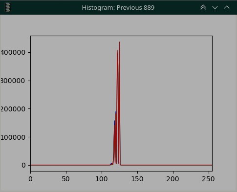
  2. Set a fixed exposure in such a way that .jpg-images delivered by your camera show a level around 128 in the green channel of your images.
  3. Now adjust the blue gain in such a way that the green and blue channel values are approximately the same.
  4. Next, adjust the red gain so red and green channels share the same values.
  5. Repeat steps 3. and 4. until the values of all color channels have converged to approximately the same value (around 128).

The above procedure will assure that your camera looking at your light source will see just a boring grey image. If you notice any intensity or color variations in that image, you need to check your hardware setup. Some of the things which can happen:

  1. Dark spots, either sharply focussed or blurry - that is usually caused by dirt on either the diffusor of your light source, the lens or the sensor itself. Clean the stuff.
  2. Vignetting - can be caused either by not diffusing enough in the light source, or by the lens being of less than perfect quality. This could be solved by an appropriate lens shading compensation in software (but: quite a deep dive into libcamera’s lens shading algorithm required, plus the challenge of capturing appropriate calibration images) or by improving the hardware (either improving the light source or choosing a better lens, depends where the vignetting is happening).
  3. Color variations - that should actually not happen with a whitelight LED. Can easily happen if using separate LEDs for red, green and blue with not enough mixing occurring in the light source. Might happen with a whitelight LED if for example strongly colored areas are close to your LED which reflect light onto the frame as well.

Anyway. Once you have arrived at a nice grey image in the above setup, you should be good to go for an initial scan of your film stock. Insert a film, adjust the exposure for the film and see what you get.

Different film stock will have different color characteristics of the dyes and film base. The white balance you achieved with the procedure above should get you close to a film-specific white balance, but probably not quite to the point. You can fine-tune your manual whitebalance point by the following procedure:

  1. Adjust your exposure in such a way that the brightest areas of your film scan are again a medium gray.
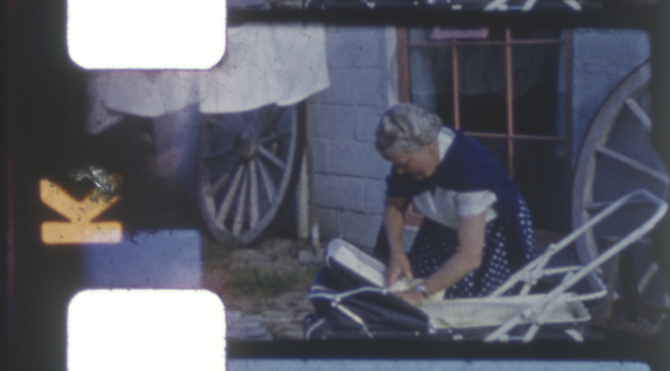
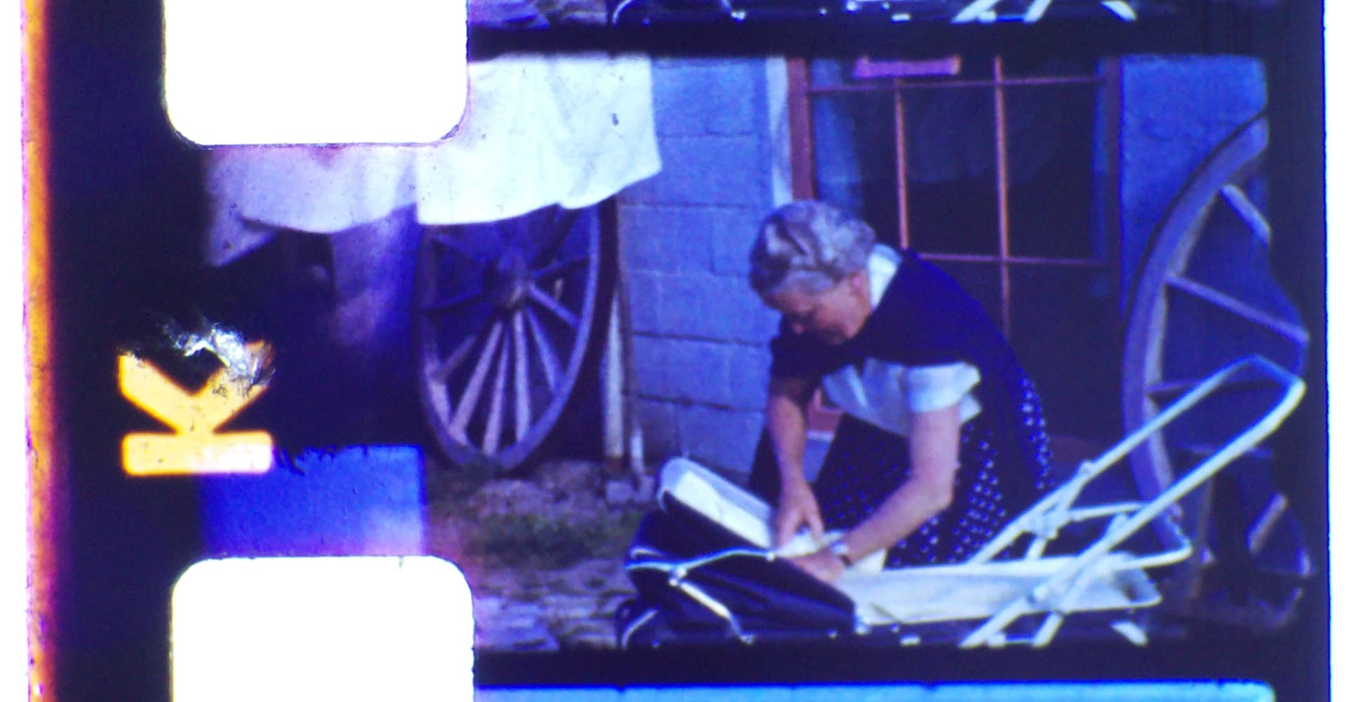
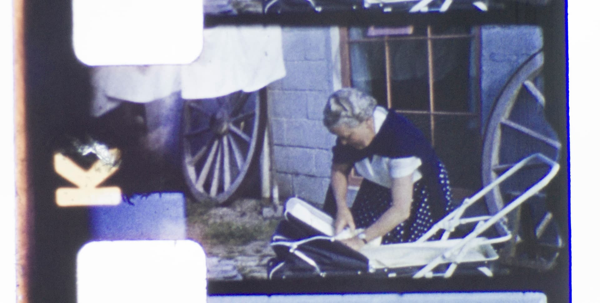
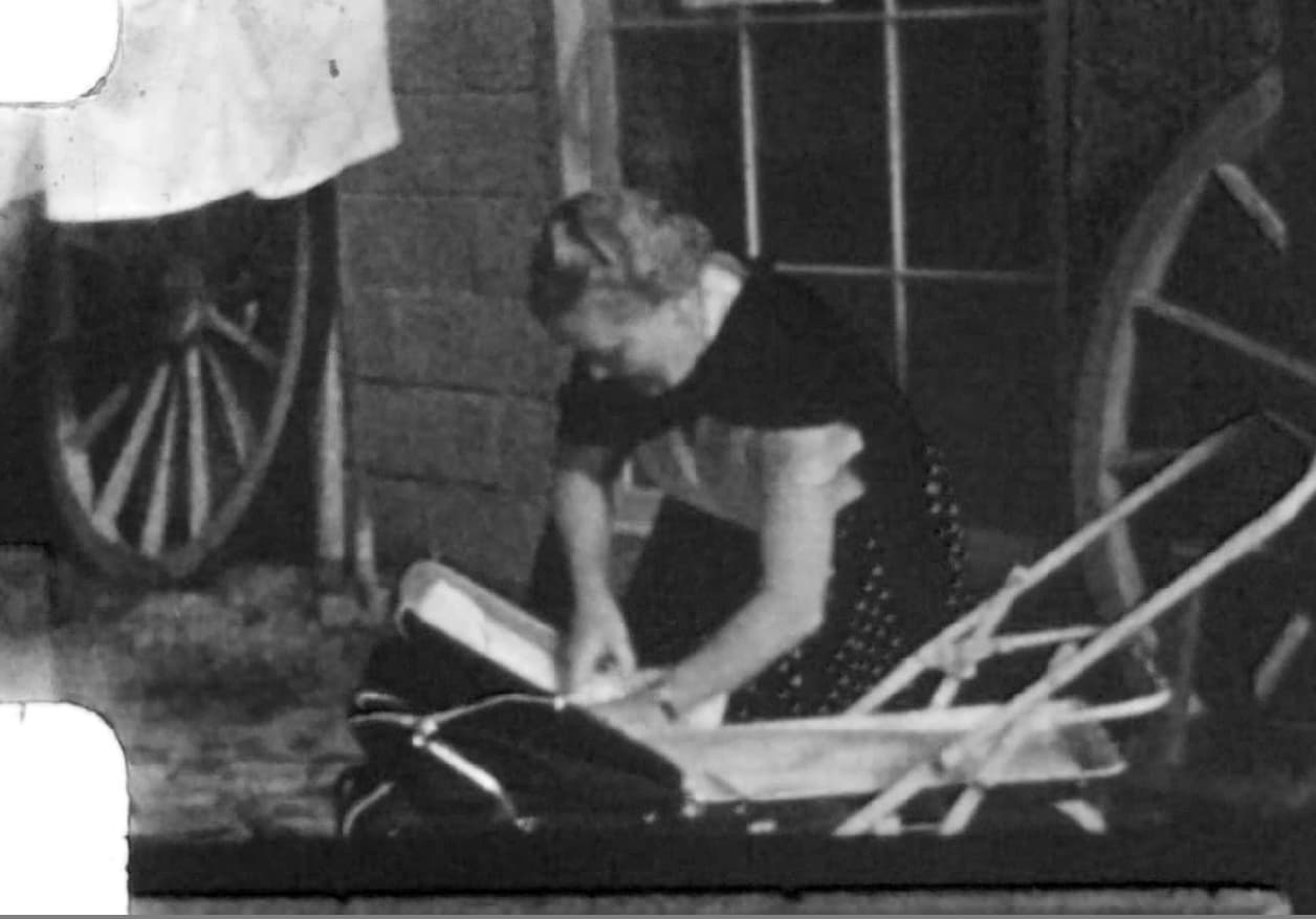
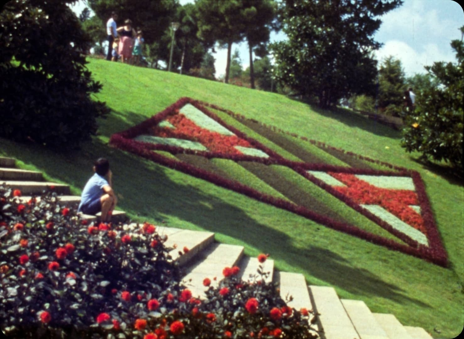
  2. Make sure that the content of these areas of interest are indeed expected to be “white” (or, in our case, “grey”). Do not use things like the sun or other areas which originally had a color. In your above scan, for example the laundry in the background would be an appropriate target).
  3. Adjust again your red and blue gain in such a way that these brightest image areas all have similar values in the red, green and blue color channels.

(A note of caution: I have experienced sometimes an unwanted color shift at this point of procedure. For example, I have Kodachrome film stock which has a tiny magenta color shift in very bright image areas. In this case, it is better not to use the brightest image areas for this fine-tuning, but rather image areas with a medium intensity which are known to be grey in the original scene. Or: simply stick to the whitebalance setting you have obtained in the first adjustment step.)

At this point you should have color-wise a scan quality which is usable. As I mentioned above, the whitebalance of amateur film stock is anyway never spot on, because only two different color temperature were available (daylight and tungsten) when the original recording happened. So it’s pure luck to have a match. Furthermore, there were also variations in the processing labs, leading to small color shifts between different film rolls. While that was barely noticable when projecting the material in a darkened room, your scanner will pick these color shifts up. But these kind of color variations can easily be handled in postproduction.

4 Likes

Thank you for so much valuable information, I really appreciate it and I’m going to work my way through a few times what you’ve written.

When I say ‘blue halos’ I was referring to what I notice (other than the massive blue cast) in the original two pictures up top around the outside of the prams white handles.

I think what is also not helping at all is that I haven’t put a film gate on it yet, which means the film is sometimes a little slack going through it and consequently, a little warped by gravity which doesn’t help with focus!!

The light source (or LED) would affect the intensity of the color. If the sensor is saturated, some color may spill… but it doesn’t look like it.

A color displacement (blue where there was no blue) is probably something related to optics or focusing. Check your lens best aperture for sharpness and resolution, that may be a factor.

1 Like

Ah, ok. I understand. Difficult to say where this comes from. If you look at the red channel of your jpg-file,

you see at these positions a rather low signal in the red channel. Note that the same dark signal streaks appear at the frame border (bottom of your scan), between the bright sky and the frames boundary. It seems to affect mostly strong contrast horizontal edges.

Difficult to say what causes this. The blue halo is noticable in both your .jpg- and raw-scan, but not in the professional scan. So it’s probably not caused by chromatic aberation of the movie camera’s lens. However, the professional scan’s resolution might be to low to even notice.

If it would be caused by chromatic aberration of your scanning lens, one would expect the same issue also to be present around the sprocket holes. That’s not really what I see. Your lens seems to performs well, at least around the sprocket area. Not sure about the right border of your raw scan - is the blue line visible here a result of your raw processing, or is that already in the image data?

So, this type of halos remains a mystery to me, at least with the currently available information.

1 Like

Hi @Rowan,

In my device for transporting the film I use an old 8mm/Super8 projector.
In this projector, as in many others, the space for the lighting system is quite limited. For this reason, from the beginning I have always used, with more or less success, commercial white light LED lamps.
The one I currently use is the following:

It is a very cheap lamp, €1.3. I do not know the CRI parameter that does not appear in the technical data.
However, in my opinion, for 8mm film scanning application, it gives good results.
For the adjustment of the white balance, in its day I used exactly the same procedure described by @cpixip
Attached is the histogram of the image captured by the RPi HQ camera with no film threaded in the projector.
In the histogram there are actually three superimposed curves corresponding to the blue, green and red channels. Only the red curve is visible, which is the one drawn last.
An ideal histogram would be three overlapping vertical lines. It would mean that all pixels receive the same level of illumination. Of course this is impossible to achieve in practice. Instead we should try to get the base of the curves as narrow as possible, meaning there is little spread in light levels.

The histogram and images in the above link were taken on the HQ camera using the old Picamera library.
As a comparison, I attach histogram and an image of the same frame captured with the HQ camera but using the new Picamera2 library. The camera has been tuned with the imx477_scientific.json file (@cpixip thanks for sharing)

Histogram

I am finalizing a new version of my DSuper8 software that already uses the new library. I hope to post it on the forum shortly, as with previous versions.

Regards

3 Likes

You don’t have a gate holding the film flat so of course you have that limitation.

In terms of the colour, you need a high CRI white light, there’s really no alternative there (other than building a full-spectrum RGB light) and it will improve the dynamic range you’re getting by an order of magnitude. Your scan, no matter the initial colour-cast which may be removable, is missing entire wavelengths of colour because the light isn’t conveying it to the camera, and that’s what’s causing the limited dynamic range.

Because 90 CRI isn’t very high, at all. The price escalates as you go higher CRI, and you should should stick to a reputable brand like Yujiled and stick away from ebay. :slight_smile:

1 Like

Having a rather brutal time trying to ‘learn’ the ins and outs of picamera2
The Picamera2 Library (raspberrypi.com)

All I want to do is switch to cpixip’s scientific tuning file, but I can’t find any instructions on how to do so - I thought that reading the manual might shed some light on it, but the commands at the start of the manual don’t seem to work anymore, I heard a rumour that the updated OS has borked it? I’m hesitant to carry reading. What a headache!! Argh!
Does anyone have any suggestions on where I might look for answers, or which path I should be looking at now?

Hi @Rowan,

Certainly the beginnings are not usually easy. We must break the ice before starting to develop our own ideas.

I usually update my RPi once a week and the HQ camera with the picamera2 library works fine.

Perhaps the manual does not explain certain aspects of the library in sufficient detail.

In my case, as I was reading the manual, I was testing sending commands to the camera in an ipython console.

I plan to publish soon the latest version of my software that uses the picamera2 library.

Actually the final version of the software is already finished. Now I am preparing a user manual. As soon as I have it finished I will publish the software.

However, I am attaching the camera.py file where you can see how I am managing the camera. I think it works quite well.

I have tried to make it clear and didactic enough.

Study it carefully. If there is something that is not well understood, please let me know.

Regards

“”"
DSuper8 project based on Joe Herman’s rpi-film-capture.

Software modified by Manuel Ángel.

User interface redesigned by Manuel Ángel.

camera.py: Camera configuration.

Latest version: 20230430.
“”"

from picamera2 import Picamera2, Metadata

from time import sleep

from logging import info

class DS8Camera():
off = 0
previewing = 1
capturing = 2

# Resolutions supported by the camera.
resolutions = [(2028, 1520), (4056, 3040)]

def __init__(self):

    tuningfile = Picamera2.load_tuning_file("imx477_scientific.json")
    self.picam2 = Picamera2(tuning=tuningfile)

    # Configured resolution.
    self.resolution = self.resolutions[0]

    # Geometry of the zone of interest to be captured by the camera.

    # Coordinates of the upper left corner.
    self.x_offset = 0
    self.y_offset = 0

    # Zoom value. Determines the width and height of the zone of interest.
    # Values between 0.4 and 1. They are given by the zoom control.
    self.roiZ = 1

    # Width of the image.
    self.width = self.resolution[0] * self.roiZ

    # Height of the image.
    self.height = self.resolution[1] * self.roiZ

    # Automatic exposure.
    self.autoExp = False

    # Automatic white balance.
    self.awb = False

    # Number of bracketed exposures.
    self.bracketing = 1

    # Stop points.
    self.stops = 0

    # Manual exposure time.
    self.ManExposureTime = 2500

    # Automatic exposure time.
    self.AeExposureTime = 2500

    # Actual exposure time requested from the camera.
    self.exposureTime = 2500
    
    # Minimum exposure time. It is fixed at 10 us.
    self.minExpTime = 10

    # Maximum camera exposure time.
    # According to technical specifications of the camera, it can reach a
    # maximum of 670.74 s.
    # For our application we will set it to 1 s.
    self.maxExpTime = 1000000        

    # Metadata of the captured images.
    self.metadata = None

    # Camera capture speed in fps.
    self.frameRate = 10

    # Camera settings.
    # These settings are applied with the camera disabled.
    # It's not possible modify them with the camera active.

    # Allocate a single buffer.
    self.picam2.still_configuration.buffer_count = 1

    # Flip the image vertically
    self.picam2.still_configuration.transform.vflip = True
    self.picam2.still_configuration.transform.hflip = False

    # No images in preview.
    self.picam2.still_configuration.display = None

   # No streams are encoded.
    self.picam2.still_configuration.encode = None

    # Color space.
    # This feature is automatically configured by Picamera2.

    # Noise reduction:
    # This feature is automatically configured by Picamera2.

    # Duration time of the frames.
    self.picam2.still_configuration.controls.FrameDurationLimits = (self.minExpTime, self.maxExpTime)

    # Dimensions of the captured image.
    self.picam2.still_configuration.main.size = self.resolutions[0]

    # Image format 24 bits per pixel, ordered [R, G, B].
    self.picam2.still_configuration.main.format = ("RGB888")

    # Unknown parameters.
    # Default configuration.
    self.picam2.still_configuration.main.stride = None
    # self.picam2.still_configuration.framesize = None
    self.picam2.still_configuration.lores = None
    self.picam2.still_configuration.raw = None

    # Do not allow queuing images.
    # The captured image corresponds to the moment of the capture order.
    # To queue images the buffer_count parameter must be greater than 1.
    self.picam2.still_configuration.queue = False

    # Loading still image settings.
    self.picam2.configure("still")

    # Camera controls. These parameters can be changed with the
    # camera working.

    # AeEnable:
    # AEC: Automatic Exposure Control.
    # AGC: Automatic Gain Control.
    # False: Algoritm AEC/AGC disabled.
    # True: Algoritm AEC/AGC enabled.
    self.picam2.controls.AeEnable = False
    
    # This variable gives error "Control AEConstraintMode is not advertised by libcamera".
    # However, with the camera started it can be referenced normally. 
    # AEConstraintMode:
    # 0: Normal. Normal metering.
    # 1: Highlight. Meter for highlights.
    # 2: Shadows. Meter for shadows.
    # 3: Custom. User-defined metering.
    # self.picam2.controls.AEConstraintMode = 0

    # AeExposureMode:
    # 0: Normal. Normal exposures.
    # 1: Short. Use shorter exposures.
    # 2: Long. Use longer exposures.
    # 3: Custom. Use custom exposures.
    self.picam2.controls.AeExposureMode = 0

    # AeMeteringMode:
    # 0: CentreWeighted. Centre weighted metering.
    # 1: Spot. Spot metering.
    # 2: Matrix. Matrix metering.
    # 3: Custom. Custom metering.
    self.picam2.controls.AeMeteringMode = 0

    # ExposureTime: value between 0 and 1000000 us
    self.picam2.controls.ExposureTime = 4000

    # NoiseReductionMode: configuration parameter.

    # FrameDurationLimits: configuration parameter.

    # ColourCorrectionMatrix

    # Saturation: value between 0.0 and 32.0. Default 1.0.
    self.picam2.controls.Saturation = 1.0

    # Brightness: value between -1 and 1. Default 0.0.
    self.picam2.controls.Brightness = 0.0

    # Contrast: value between 0.0 and 32.0. Default 1.0.
    self.picam2.controls.Contrast = 1.0

    # ExposureValue: value between -8.0 and 8.0. Default 0.0.
    self.picam2.controls.ExposureValue = 0

    # AwbEnable:
    # AWB: Auto white balance.
    # False: Algoritm AWB disabled.
    # True: Algoritm AWB enabled.
    self.picam2.controls.AwbEnable = True

    # AwbMode:
    # 0: Auto. Any illumant.
    # 1: Incandescent. Incandescent lighting.
    # 2: Tungsten. Tungsten lighting.
    # 3: Fluorescent. Fluorescent lighting.
    # 4: Indoor. Indoor illumination.
    # 5: Daylight. Daylight illumination.
    # 6: Cloudy. Cloudy illumination.
    # 7: Custom. Custom setting.
    self.picam2.controls.AwbMode = 0

    # ScalerCrop:
    self.picam2.controls.ScalerCrop = (0, 0, 4056, 3040)

    # AnalogueGain: value between 1.0 and 16.0.
    self.picam2.controls.AnalogueGain = 1.0

    # ColourGains: value between 0.0 and 32.0
    self.customGains = (2.56, 2.23)
    self.picam2.controls.ColourGains = self.customGains

    # Sharpness: value between 0.0 and 16.0. Default 1.0.
    self.picam2.controls.Sharpness = 1.0

    self.mode = self.off

    # Starting up the camera.
    self.picam2.start()

    sleep(1)

# Initial settings.

# zoomDial

def setZ(self, value):
    self.roiZ = float(value) / 1000

    self.x_offset = int(self.resolutions[1][0] * (1 - self.roiZ) / 2)
    self.y_offset = int(self.resolutions[1][1] * (1 - self.roiZ) / 2)

    self.width = int(self.resolutions[1][0] * self.roiZ)
    self.height = int(self.resolutions[1][1] * self.roiZ)

    self.picam2.controls.ScalerCrop = (self.x_offset, self.y_offset,
                                       self.width, self.height)

# roiUpButton - roiDownButton
def setY(self, value):
    self.y_offset = value
    self.picam2.controls.ScalerCrop = (self.x_offset, self.y_offset,
                                       self.width, self.height)

# roiLeftButton - roiRightButton
def setX(self, value):
    self.x_offset = value
    self.picam2.controls.ScalerCrop = (self.x_offset, self.y_offset,
                                       self.width, self.height)

# Camera settings.

# awbBox
def setAwbMode(self, idx):

    if idx < 7:
        self.awb = True
        self.picam2.controls.AwbEnable = self.awb
        self.picam2.controls.AwbMode = idx
    else:
        self.awb = False
        self.picam2.controls.AwbEnable = self.awb

    if idx == 0:
        mode = "auto"
    elif idx == 1:
        mode = "incandescent lighting"
    elif idx == 2:
        mode = "tungsten lighting"
    elif idx == 3:
        mode = "fluorescent lighting"
    elif idx == 4:
        mode = "indoor lighting"
    elif idx == 5:
        mode = "daylight"
    elif idx == 6:
        mode = "cloudy"
    elif idx == 7:
        mode = "custom lighting"
    elif idx == 8:
        mode = "manual"
    else:
        return

    info("Adjusted white balance " + mode)

# blueGainBox, redGainBox
def fixGains(self, idx, value):

    self.metadata = self.captureMetadata()

    if (idx == 0):
        gred = value
        gblue = round(self.metadata.ColourGains[1], 2)

    elif (idx == 1):
        gred = round(self.metadata.ColourGains[0], 2)
        gblue = value

    self.picam2.controls.ColourGains = (gred, gblue)

    sleep(0.2)

    info("Camera color gains: blue = " + str(gblue) + ", red = " + str(gred))
         
# Capture.

# captureStartBtn
def startCaptureMode(self):
    sleep(1)
    self.mode = self.capturing
    info("Camera in capture mode")

# Advanced settings.

# constraintModeBox
def setConstraintMode(self, idx):
    self.picam2.controls.AeConstraintMode = idx        

    if idx == 0:
        mode = "normal"
    elif idx == 1:
        mode = "highlight"
    elif idx == 2:
        mode = "shadows"
    else:
        return

    info("Adjusted auto exposure restriction " + mode)

# exposureModeBox
def setExposureMode(self, idx):
    self.picam2.controls.AeExposureMode = idx
    
    if idx == 0:
        mode = "normal"
    elif idx == 1:
        mode = "sort exposures"
    elif idx == 2:
        mode = "long exposures"
    else:
        return

    info("Adjusted auto exposure mode " + mode)

# meteringModeBox
def setMeteringMode(self, idx):
    self.picam2.controls.AeMeteringMode = idx
    
    if idx == 0:
        mode = "centre weighted"
    elif idx == 1:
        mode = "spot"
    elif idx == 2:
        mode = "matrix"
    else:
        return

    info("Adjusted auto exposure metering mode " + mode)

# resolutionBox
def setSize(self, idx):
    self.picam2.stop()
    self.picam2.still_configuration.main.size = self.resolutions[idx]
    self.picam2.configure("still")
    self.picam2.start()
    if idx == 0:
        resol = "2028x1520 px"
    elif idx == 1:
        resol = "4056x3040 px"

    info("Camera resolution " + resol)

# This function is used to capture the metadata of the images.
def captureMetadata(self):
    metadata = Metadata(self.picam2.capture_metadata())

    return metadata
2 Likes

@Rowan, I am also starting from scratch both on the library, the sensor, and python.

When eating an elephant, I do so one part at the time.
I am getting familiar with the setting of the camera with libcamera-hello, then progressing to libcamera-still. It is simple enough to play with. One tip, the json file from @cpixit needs to be at the directory from where you are starting the libcamera command, or the entire path should be included. See this posting.

If you are already programming something, this posting is also a great step by step tutorial by @cpixip.

And lastly (as mentioned above), the implementation by @Manuel_Angel is a great see-how example.

PS. I also found this post by @PixelPerfect ,and the discussion above and below regarding the library (which is about multi-exposure) a great basic python code to get started and understand how the library works.

2 Likes

Hi guys,

Just to get a feeling about how to tackle multi exposure with latest software stack available on raspi with hq cam:

do you control the brightness of the :bulb: and keep camera settings static or do you use constant lighting and change exposure time for bracketing?

Would be awesome to get a overview and the pros and cons you experienced
Greets
Simon

I suggest to change exposure times while keeping the illumination constant. There several reasons for that.

  • with current picamera2/libcamera software you can do that without waiting 3 to 5 frames for an exposure change, as it was standard in the past.

  • the frames come with metadata, so you can build up your stack and trigger frame advance once the stack is full.

  • switching the illumination and keeping exposure time constant reqires some sort of sync between frames and illumination switch. Not easy, as most RP cameras are rolling shutter ones. So occationally, the switch will happen in the middle of a frame. You would need to detect that and throw away that frame. Or: devise some hardware triggering. While that can be done, the voltages involved are tiny and the electronics fragile.

I tried both approaches, with the varying exposure one resulting in three to four times higher capture rates. Qualitywise, I could not see any difference between both approaches.

1 Like

Thanks for your summary, great writeup as always!

Im convinced that the speedup together with the easier handling is an advantage that can’t be beaten, the goal is set, off to code!

@d_fens - some further hints with respect to your software development:

  • after you request a specific exposure value, it takes quite an amount of frames for this request to “travel” towards the camera. Once the camera has taken this frame with the requested exposure, it takes again a few frames to show up at the request frontend of the picamera2 software. Expect a delay of 11 to 12 frames after changing the exposure!

  • if you request a certain exposure from libcamera, say “2432”, you will not get that. There is only a certain set of exposure values realizable directly in hardware. All other exposures are simulated by libcamera by using a digital gain different from 1.0. That is the reason you can no longer set any digital gain in picamera2 as compared to picamera1. In my example, the real exposure time would be somthing like “2400”, with a digital gain of about 1.013 applied afterwards. Luckily, this will show up in the metadata associated with the frame. In general, exposure requested will not be equal to exposure delivered.

So there are some challenges to circumvent if you are going along the exposure-based HDR route. Here’s what works for me:

  1. The driving camera software constantly circles the set of required exposure times. After a short delay the frames delivered by the camera are following this cyclic exposure pattern.

  2. After a frame advance, the HDR-stack is emptied. The incoming data is scanned for the real exposure time of the current frame. Whatever this exposure time is, the frame is inserted in the correct place of the HDR-stack. Repeat with the following frames (they will have a different exposure time because of 1.).

  3. Once the full HDR-stack is obtained, trigger a frame advance. Wait for some time to allow the mechanical system to settle to a steady state. Start again with 2.).

With respect to point 2.) above, you have to take both exposure time and digital gain into account. Only the product of both does matter and should be equal to your requested exposure time.

In previous version of libcamera/picamer2, the digital gain applied used to adapt rather slowly after an exposure change, which made things even more difficult - occationally, you would have to skip 2 or 3 frames to come even close to your requested exposure. This has been improved in recent versions, I have however not checked the most recent one on this issue.

Anyway, there are two approaches you could take here:

  1. use only exposure times which are directly realizable by the hardware. In my example above, “2400” would be such an exposure time. In this case, digital gain will be 1.0 for certain.

  2. use whatever exposure times you want to use, but set a limit for the deviation of the digital gain from 1.0.

Here’s my actual code I am using with approach 2.) for this purpose:

            # if we find an appropriate exposure, delete it from list and
            # signal that the frame should be saved
            if abs(self.metadata['ExposureTime']-expo)/expo < self.dExpo   and \
                   self.metadata['DigitalGain']             < self.dGain:

with dGain = 1.01 (allowed variation of digital gain) and dExpo = 0.02 (allowed percentage of deviation between requested exposure and actual exposure.

These limits work fine with exposure fusion algorithms (“Mertens”); for calculating a real HDR from the HDR-stack, you have to calculate for each frame the real exposure as

rExpo = self.metadata['DigitalGain']  * self.metadata['ExposureTime']

and use this for HDR-computation.

Finally, be sure to use either the alternative “imx477_scientific.json” tuning file or be sure to switch off some automatic algorithms hidden in libcamera when using the standard one.

2 Likes