My approach to improving the Kinograph

25 years ago, back in the days of Betamax, I attempted to archive my large collection of 8mm home movies by recording them ‘off the wall’ with my newly acquired (and hugely expensive) Sony SL-F1 system.This was relatively successful, mainly due to the fact that the camera had a Trinicon imaging tube which had long persistence by today’s standard so virtually eliminating flicker. Most TVs in those days rarely exceeded 21", and everything was in SD, so the result was quite acceptable. However, I knew that one day I would have to repeat the process because I anticipated that the digital revolution was bound to enter the home movie-making arena sooner or later.

When I retired in 2014 I thought ‘now is the time’, because the technology to do every aspect of it was here. Now the pressure was even greater because by then I had also inherited a huge archive from my late father and my great-uncle both of whom had spent all their lives in the film production industry back as far as the late 1800s. Now, not only did I have 8mm to convert, but also 9.5mm, 16mm, and hand-perforated 35mm.

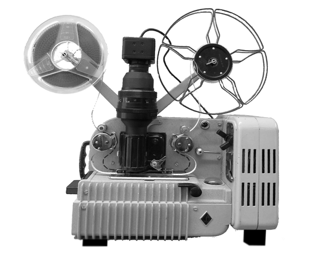
Last year I decided to start with the 8mm reels, and I had great success converting my vintage Eumig projector to do the job. This projector was beautifully engineered, very gentle on the film, and easy to modify using parts made on my 3D printer.

Originally I used a Microsoft LifeCam Studio as the sensor, but I show here an MC500 which I have recently been experimenting with.

However, I did not have a projector for any of the other guages, so I set about making one of my own using an intermittent claw mechanism that I designed and which I have talked of elsewhere on this forum. I was concerned however that this may not be the most sensible way to handle the earliest films, the youngest of which were from the 1950’s, and stretched back through every decade to around 1895.

So, I trawled the internet looking for information that would help me move forward. About 6 weeks ago I stumbled across the Kinograph and this forum, and I knew that this was where I was going to get the inspiration that I needed, and a good place to hang-out. I also realised that the machine was still a ‘work in progress’, and that there were a few problems still to address which was exciting for me because it meant that I could build a machine of my own and experiment with solving those problems. As a technologist, that is the kind of thing I have done all my working life in various fields, but now I could have fun doing it for me!

That is what this post is about. I have been chatting privately to Matthew about the direction I am moving in, and he is keen that I share it in this forum and open it to discussion - so here goes…

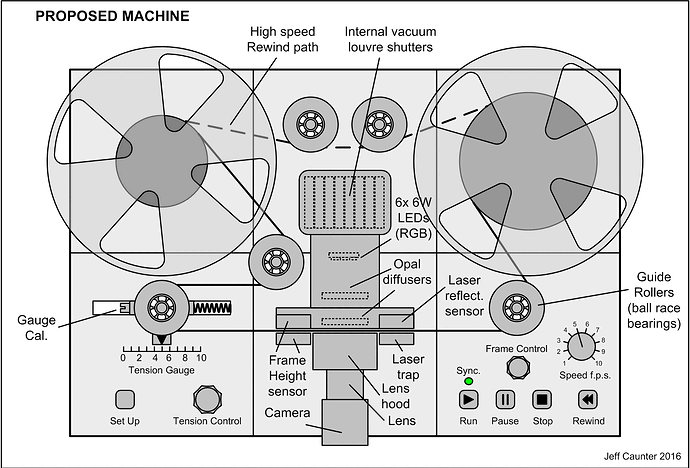
Firstly, I will show you my proposed version of Kinograph so you can put the details that I am about to describe into context:

This machine will be about 90% carbon-fibre plastic made of parts produced on my 3D printer. The chassis is made of 6 ‘tables’ 200 mm (~ 8") square that are pinned and bolted together to provide high rigidity and strength. I called these ‘tables’ because they each have 4 legs which provides clearance for the motors beneath, and makes the whole thing aesthetically pleasing. To get some idea of the scale of this drawing, the reels are 10" diameter.

Here are the main attributes of the design -

  • There are no sprockets on the rollers.
  • The emulsion side of the film never touches anything.
  • A ‘vacuum gate’ gently flattens the film against the ‘shiny side’ during the short period of frame capture.
  • The complete transport mechanism is stabilised by a simple low-cost
    closed-loop hybrid control system (analogue/digital).
  • High immunity to missing/broken sprocket holes.
  • Film tension is adjustable, and automatically maintained.
  • Film speed is adjustable and automatically maintained.
  • Longitudinal framing is adjustable without moving the camera and is
    accurately maintained.
  • Sprocket hole sensing is achieved by reflective laser.
  • Provision for optional lateral frame stabilisation (later).
  • Provision for gentle rewinding with constant tension.
  • Auto shut-down if film breaks or end-of-reel.
  • Easy set-up mode for pre-focusing etc.

Before I introduce the control system, I need to briefly mention the sprocket-hole sensor that I am going to use. Although it is possible that the existing micro-switch arrangement could be used because it would be stabilised by the control loop, I have discounted this as I wanted to have rollers free of sprockets.

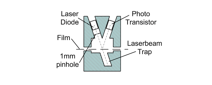
After a period of experimentation with a variety of designs and using different types of transmitters and sensors, I finally settled on this one which I built using a cheap laser diode and photo-transistor in a reflective layout as shown here -


Although it is described as ‘reflective’, this is not meant in the ‘mirror’ sense, which is what an l.e.d. would rely on. Unlike an l.e.d. the beam from a laser is ‘coherent’, which means that the photons are all in phase with each other. When they strike a surface the reflection produces a constructive/destructive ‘interference pattern’ that appears to us as a granular, twinkling, effect. This will occur regardless of whether the surface is transparent or not, which is just what we want. To ensure that the diameter of the beam is smaller than the sprocket hole, it is passed through a small pinhole, and to prevent the beam from falsely illuminating the sensor, it is caught in a trap as shown.

Now look at how the sensor is likely to perform -

This diagram is somewhat exaggerated, but it illustrates that the output from the sensor will be a stream of pulses that have an average period that exactly matches the period between the sprocket holes, but that the edge of each pulse will have a degree of uncertainty which will be reflected in the timing of the capture. This will result in a vertical jitter in the captured video.

To overcome this we need something special to clean up these pulses, so now for the interesting bit - the control system. This is based on a ubiquitous system device known as a Phase Locked Loop (PLL). There are billions of them in use today all around the world in one form or another, and most of us have many spread throughout the electronics in our homes, offices, and cars, not to mention our pockets (cellphones, mp3 players etc).

See this for a good primer on PLLs

There are many ways in which a PLL can be used, and here is a conceptual diagram of the configuration we would need to overcome our jitter problem.

In effect, it is working like a flywheel, smoothing out the jitter but, unlike a flywheel, not only are the input/output frequencies locked, but their phases are too. Imagine two identical cars travelling side by side on a road. They may well be moving at identical speeds, but unless they are dead-alongside each other, they will not be in phase.

This will almost certainly help a great deal to improve the trigger performance of the existing Kinograph, but it does nothing to stabilise the frame rate of the film, and without that it is difficult to control the tension, so I wanted more from my system.

It took a couple of days to think this through, but I finally came up with a solution that is somewhat unusual, which involves using a DC motor for take-up, and turning the PLL on it’s head by removing the VCO and replacing it with the motor/film/sensor combo. In effect, this combo responds to changes in motor voltage by changing the output rate from the sensor, just like a VCO. Now, all we have to do is to apply an appropriate clean pulse stream to the input of the PLL, and the sprocket holes in the film will be locked to it, in both frame rate and position (phase). What is more, because we are using a PMDC motor, which has an inverse torque/speed relationship, the loop conditions will not be upset as the diameter of the film on the spool changes. Naturally, the camera will be triggered by the clean pulse generator.

A further improvement to this may be to add a conventional PLL between the sensor and the phase comparator to improve the jitter reduction even further and enhance immunity to damaged sprocket holes, but I won’t know if it is necessary until I have constructed the system for real. However, this may be vital if an electronic ‘framing’ control is introduced, since this is where the ‘phase’ can be conveniently adjusted.

So far, all these details are theoretical, although a large part of it has been run through a simulator (SciLab + Xcos) on my PC, and all seems to be OK so I will continue with it.

Other aspects worth mentioning.

  • The supply reel will use an identical motor to the take-up, to
    provide constant tension with changing film diameter, but will be
    driven differently because it is essentially working ‘backwards’.
  • I have incorporated a gauge to monitor tension, and a screw to
    calibrate it.
  • The film gate is a departure from the norm in that there is no
    pressure plate. The film is held flat against the frame aperture by
    vacuum for the brief period of frame capture, but is free to float at
    other times… The vacuum is provided by two PC case fans, and
    switched by a shutter working on a louvre principle. The precise
    details of this are still floating in my mind, but I have also toyed
    with the idea of using the shutters closer to the film where they
    could also shutter the lamp. I may even dispense with the shuttering altogether and leave the vacuum on permanently - i’ll see how it goes.
  • Film rewinding will be simple because the two motors are identical,
    and their roles can be easily switched. Slow rewinding can be done
    using the normal film path, but fast rewinding, with tension control
    can be performed using the back rollers.
  • The knobs and switches I show are something that will appear after I
    am happy with the system performing its major tasks. They will
    probably interface to an Arduino, which will also handle safety
    features and idiot-proof interlocks.

And what is all this likely to cost?

Ignoring the cost of the motors, It is likely that the complete electronics system will be less than $20. The motors may be another $40 or thereabouts, but I’m still working on an optimum model type to use.

Overall, without the camera, I guess the machine could be built for less than $100, and this is using components at 1-off prices.

Well, that’s enough for now, maybe too much? Anyway, there are still many details that I have left out for the sake of brevity, but soon I will be putting them down in a pdf, as much for my benefit as anyone else.

Any comments or suggestions?

To be continued…

Jeff
3 Likes

amazing post, @VitalSparks. This is fantastic, clearly explained and very thorough. Can’t wait to see how others respond. Thanks for putting so much thought into it. It’s a great resource and I’ll definitely be referring to it along the way.

My pleasure, that is to say I am getting a great deal of satisfaction from being able to contribute to such a facinating project, and there are some really interesting technical challenges here, that are ‘right up my street’.

I know I still have some way to go to turn my ideas into reality, but there were two areas that I needed to visit before embarking on the design and construction phases in order for all aspects of my version of the Kinograph to move forward on a common front. The first was the light source, and the second was the imaging device (I prefer this description rather than ‘camera’ in this context). So, over the last week I have been concentrating on these.

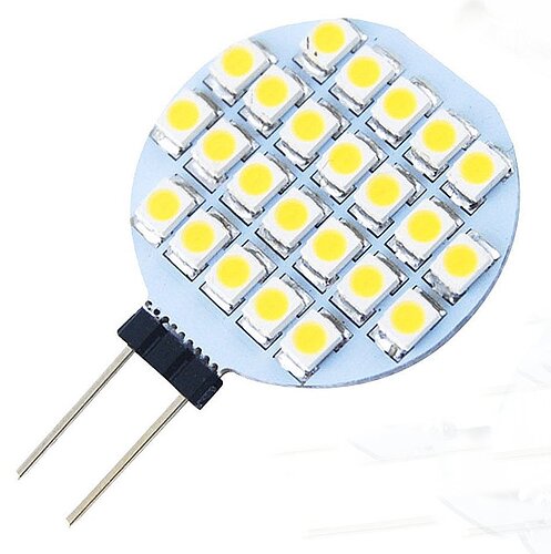
I started by considering a suitable light source. I had originally thought that providing an array of separate RGB leds was the way to go, but now I’m not so sure. A quick experiment with a few coloured leds highlighted the difficulty of combining them to produce a clean homogeneous beam without losing a significant amount of light. So I then scoured the market looking for something commercially available that could get close to the spectral output from a xenon flash tube, and I stumbled across this -

This actually looks quite exciting because it has none of the power-regulating electronics that most 12v domestic lamps have, and which usually thwart any attempt to use them outside their designed mode of operation. This little beauty is from a socket family known as G4, is available in several colour temperatures, and consists of 8 sub-arrays each comprising 3 leds in series with a chip resistor, and all being fed in parallel from a bridge rectifier whose input is designed for 12v ac/dc. The assembly is about 1" diameter - connector can be easily unsoldered and replaced with wires. I don’t know what application they were originally intended for, but they look ideal for a Kinograph.

I bought 4 of them (~25p each! 40c?) to try them out, and have been very impressed so far. I chose ones with a colour temperature ~6000K, which is pretty close to that of a photo flash gun. The 24 leds are type SMD2835 if you want to Google them for a data sheet. These are rated at a max continuous current of 75mA (but would need heatsinking). I have tried the array at 600mA total (8x75mA), and the light is brilliant - calculated ~800lm. This was with a drive voltage of 20v. The beauty is that the light output can be easily adjusted just by varying the voltage because there is no switching regulator - it seems that the colour temperature will stay pretty constant over a wide range of voltage too.

Now for the imaging device. I have been studying the technical data sheet for the MT9P006D, which I mentioned elsewhere and is the chip inside my MC500 camera (£63 ~ $100). I am now convinced that this is capable of performing as well as a budget-priced Machine-Vision camera ($1000+). I originally thought it only operated as a rolling-shutter device, but I now see it has other shutter modes including one called Global Reset Release, which is a poor-man’s Global Shutter but, in the Kinograph application which can use a flash light source is just as good. There is also mention of a sync output for flash guns when in ‘stills’ mode, so it should be sensitive to just a couple of milliseconds illumination. The resolution in stills mode is 2592x1944 @ 14fps, and it has a multitude of video formats up to 1080p, and frame rates up to 123fps (640x480). I think the frame-rate of my MC500 will be limited by the USB bandwidth and speed of my capture software and PC. I haven’t checked this aspect out thoroughly yet.

Well, that’s all for now - just thought I’d bring you up to date with what I’ve been doing over the last week.

Jeff

2 Likes

Phantastic work, Jeff!

Love the inclusion of a vacuum in the gate. Maybe add a little “blower” just before the gate, so as to remove any lose dust from the film?

With light sources, keep an eye on the CRI value, the closer to 100, the better (roughly an indicator of how well it represents natural light.)
Many light sources have spikes in certain spectra, which can lead to ueven results. Especially when film is fading, unfortunate combinations of light sources and sensors can lead to the scanner being virtually blind for certain colors.

I work mainly with archive film, which can have heavily or missing perforation holes. With that in mind, some more comments:

Would be nice to make the guide rollers even bigger, so as not to damage brittle film.

Does the tension come from the take-up spool, or are any of the other roller motorized?

Would be great to be able to swap out the light sources, depending on the state and type of film. I.e. have one light source for “normal” film, one for negative, one for dupes, plus and archive one for faded colors?

Would also be great being able to record IR as a fourth channel, as that holds valuable dust/scratch information (though only works on color film).

Generally I would give everything a bit more space. That way one could also add future modules. Such as an extra camera to film the sprocket holes, camera/laser to read optical sound, module for magnetic sound? Edge-code reader?

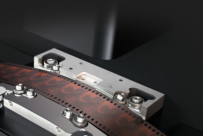
Could you employ this type of guide roller from the new Cintel ?

My gut feeling is that these rollers are good for pristine film, something that hardly exists.

1 Like

Unfortunately, this is just as likely to force more dust in the air onto the film. A vacuum may be more effective, but this too will have problems (the air has to come from somewhere - more dust?). I have been thinking about using an electrostatic approach, similar to that we used to use to attract dust from vinyl records. With the availability of conductive plastics for use in 3D printers this approach looks interesting and one that I will be experimenting with, together with micro-fine carbon brushes to neutralise static build-up (like those used in laser printers).

The array that I showed has a quoted CRI of 80, which is quite reasonable. You can download a typical datasheet for the 2835 chips HERE.

This chip has a peak towards the ultraviolet, but I would expect this to be reduced by the glass opal diffusers.

I am considering removing the tension meter, as it will not be easy to implement smoothly and without hysteresis. Instead, I will calibrate the tension control knob, which adjusts the constant-power circuit that reverse-drives the supply spool motor (constant power provides constant tension as the film changes diameter on the spool). This will allow a much smoother path for the film, which can be provided by 2 or 3 rollers of a size similar to those I originally intended. There will now be no rollers that contact the emulsion side of the film. I will be updating the picture of my proposed machine soon to reflect these changes.

No, the tension is provided solely by the supply spool motor. None of the rollers are motorised, and all have low-friction bearings. The take-up motor is only providing enough torque to pull the film at the required speed against the tension set by the supply motor.

These things are up to each individual building their own machines, and should all be easy to implement. The design that I am proposing to build is specific to my own needs, which is unlikely to include 35mm. However, the principles that I am developing should all be applicable to any configuration you choose to employ. My machine will be about 16" x 24" which is a nice size to fit on my video-editing desk. I am intending that the whole lamp/gate/camera-mount assembly can be swapped out to accommodate changes in gauge, I could even produce a version with intermittent action if I cannot successfully get the MC500 imaging device to handle continuous motion using flash.

BTW, the opal diffuser that I will be using will be mounted very close to the film because I am led to believe that this will result in a significant reduction in the visibility of scratches.

Jeff

1 Like

Nice work!

After a ton of experimentation, we stuck with the RGB LED array, laid out similarly to the white LED array you have pictured -you can easily get more light than you need, and mixing the light is easily acchieved with a diffuser and a $10 lens. I have to typically stop the lens down to f5.6 and we are only running the light at 60% brightness. It also allows you to change the mix of RGB light, which is great for faded film, and negative stocks etc. If you have access to spectral analysis gear, check the response of the light source you have, if it isn’t very spikey and missing big chunks of colour range, then that would be great, but I’d be really surprised if that was the case.

How are you focusing BTW?

To reduce scratches, you want the light source as diversely diffuse as possible, you could 3D Print a small integrating sphere and use that as the light source if you want the best scratch-removing performance.

If you encased the entire system and use positive air pressure, then you can stop any new dust being introduced, and inexpensive PTR rollers could then remove any remaining dust. A simple run through a Kelmar type cleaner between some rewinds before scanning will reduce dust and hair significantly, the rollers can pick up any of the fine bits still left.

We never had any luck with using air to flatten the film in the gate, so I hope your system works well, the flatter the film, the better the image.

I picked up an MC500 last week, it isn’t bad, the noise is much higher than the PGR Blackfly, and the capture detail in the shadow areas is much worse, but it isn’t terrible, and makes a great cheap base to experiment with. I think its two main issues are the small pixel size, it just can’t capture enough photons, and the board layout creates a bit of noise.

1 Like

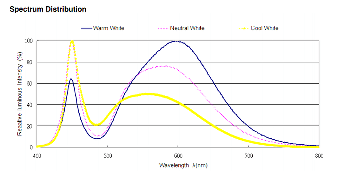
Here’s the spectrum from the data sheet for this imaging chip.


I am using the natural-white chip, but may also try the cool-white which is stronger towards the blue. I do not have access to spectral gear, so am using what we call the ‘Mk1 Eyeball’. Digital image display technology is not an exact science, so subjectively viewing the result on a computer monitor, TV, or projector has its problems. Fortunately, we humans are very forgiving in our perception of colour purity. In my case, 80% of what I’m capturing is B/W, so I’m more critical of the spatial distribution of intensity, which is more down to the quality of the diffusion method I use. For colour, I am prepared to use a variety of Wrattan filters to compensate for both the leds and the film if necessary, and make any further adjustments in the post-processing/editing phase.

At the moment, I am working with Std8 in the modified projector I showed earlier. I stop on a frame, reduce the light, and open the aperture to f1.2 (shallow d.o.f.). I focus on the frame, and then return to about f5.6-f8 (optimum for my lens), and adjust lamp intensity for best exposure. Remember I’m using intermittent motion at this time, but expect that things may be different if I find success with my continuous motion Kinograph using flash (do image chips suffer reciprocity failure, like film does?).

I don’t think 3D printing will help much here due to the non-homogeneous nature of mesh surfaces. I have instead adopted a dual-diffuser approach using opal glass which is non-granular. The lamp-house will also have matt-black corrugated walls which I hope will eliminate unwanted reflections.

This area is still ‘work in progress’ for me. I have a number of variations-on-a-theme to try here, and the first will be for the intermittent-motion gate which is likely to be the most successful, as the film will be stationary. The vacuum will be holding the ‘shiny side’ of the film against the diffuser (treated to reduce newton rings) then released after capture before the claw(s) pull down the next frame against the very light tension that the supply reel imposes.Continuous motion may not be quite so simple.

I aught to mention here that my proposed schemes for supply/take-up control are significantly different between intermittent and continuous motion. With the former, tension is provided by a balance between both the motors and motion is provided by the claws, whereas with the latter, tension is provided by the supply motor and motion is provided by the take-up motor. (hard to describe in so few words).

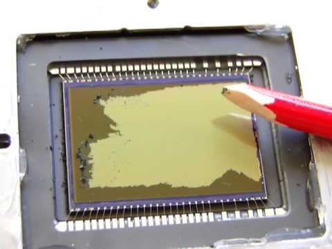
Yes, I agree with what you say, but just look at the 10:1 price difference. Like many things in this world, once you go past a critical price/performance point you rapidly follow the law of diminishing returns. I would be pleasantly surprised if this device hit that ‘sweet spot’ for continuous motion, but I selected it primarily for intermittent motion, and mainly for B/W work. The noise performance can be greatly improved here by the integration of multiple captures of each frame, and the combination of groups of 4 pixels providing only luminance must be beneficial. As for shadow detail, I think the jury is still out for me on this one. The specification suggests that it should be reasonably good, and I believe there is room for gamma adjustment. But it may be that the implementation in the MC500 is not that good. This is an area that I am still looking at. I am also going to compare it with the performance of the M$ LifeCam Studio that I also have, but it means virtually destroying it to get direct access to the image chip, so we will see…

Jeff

Th tiny pixel size on the MC500 and poor cooling/board design are its biggest problems. It is more like a 3:1 price difference, and you can go at 24fps on the alternative, which makes all the difference as it also allows you to capture sound at the same time, and if you are having to make multiple captures of each frame with the MC500, then the speed difference is even greater. I think the diminishing returns kick in at a much higher point than the MC500.

There is no reciprocity failure with sensor chips, but they have leakage issues and well saturation issues which can give similar problems, and lead to blooming, i.e. the signal leaks into adjoining cells, sometimes right down the pixel column causing smearing. I don’t get any issues with the Blackfly or Grasshopper at 24fps with an RGB LED flashed light source.

We 3D Print intgrating spheres, and they work quite well. Opal glass gives enough diffusion to ensure a flat field, but not enough to reduce base scratches significantly. An integrating sphere can work almost as well as a wetgate, if done well.

Re focusing, sorry, I wasn’t very clear, I was asking what mechanical system are you using to focus.

I’d recommend using a ‘flash’ instead of a constant light source whether going with intermittent or continuous, it usually means there is no need to cool the LED system as it doesn’t overheat, and you can control the exposure via the duration of the flash, which will freeze any residual movement even in an intermittent drive.

I really like the overall design, for the sprocket sensing, you could have a sensor either side of the gate to cater for broken or torn sockets.

[quote=“VitalSparks, post:7, topic:145”]
I have been thinking about using an electrostatic approach[/quote]

Be sure not to use Nitrate film in that case, as any static energy might set off a spark.

Has anyone seen that photo of Stan Laurel working with nitrate while smoking?
I freak out at the thought of it.

I looked at the PointGrey range at the end of last year, and was very impressed with the specifications using the Sony chips. But the cheapest model I could find to satisfy my perceived requirements at the time (I have since relaxed these) was about $1000, so I reluctantly dismissed them. However, having said that, I thought their range of cameras were very good value compared with their competitors.

Your mention of the Blackfly prompted me to go back and look again at their range, and I agree that they have several models that are much more affordable (I don’t know why I missed these), and may tempt me to invest in one if I decide to persevere with continuous motion, which I think is looking less likely with the MC500 unless running very slowly (< 3fps).

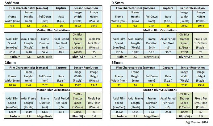
Selecting a suitable camera is not an easy task, given the variables associated with different aspects of Kinograph like frame rates, film gauge, sensor resolution, and flash settings, and their influence on ‘pixel smearing’ due to continuous motion. Up until now I have done laborious calculations at each iteration in an attempt to match these variables against affordable camera specifications. Basically, the process was not that fruitful, being too slow, open to occasional human errors, and failed to converge on a definitive answer. So this weekend I entered my equations into a spreadsheet shown here -

The result has been very enlightening, producing answers that were most unexpected, such as the film gauge having very little effect on the temporal demands of the image sensor. It is also very easy to see how the frame rate can be optimised for any particular sensor that has a global shutter, or the duration of flash illumination for those that do not, giving regard to a particular ‘pixel smearing’ performance that is considered acceptable.

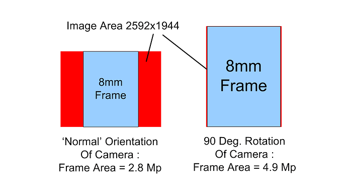
I have also been able to investigate something that I have been considering for a while - turning the sensor through 90 degrees to make greater use of its pixel real-estate. This is what I mean -


Correcting it on capture is trivial, requiring no processing - the horizontal and vertical axes are just swapped using an option available in many capture programs, along with mirroring.

All the examples I give above are set for the MC500, but any sensor characteristic can be entered into the spreadsheet. (The yellow boxes are those used to enter information, all others are locked as they contain the equations which can be read but not edited inadvertently. Users can unlock everything if they wish, but at their own peril.

I only finished the sheet a few hours ago and am still gaining confidence in the results, but when I am happy with it I will make it available to anyone that requests it.

Not really, because there is plenty of time to make several captures during the static period of the claw(s), unless attempting to operate at full frame rate which is not advisable.

This depends on how the performance is assessed. If comparing numerical specification values, then the turning point may be much higher than the MC500. However, if it is based on the subjective quality observed on (say) a 32" HD TV, then this could bring it a lot closer to something like the MC500 or even a webcam. For example, comparing two sensors with a 20dB (10x) difference in S/N ratio may look very similar on such a TV screen viewed at a sensible distance. The same goes for shadow and highlight detail, colour accuracy, contrast ratio, etc, etc. I will be viewing my own captures on a 65" Samsung 4K curved TV, which will be about as demanding as I would have thought reasonable. I still have to make this judgement however, as I am more interested at the moment in getting the transport and control aspects completed to my satisfaction.

Yes, I used to get this with my Canon Hi8 camera in the '90s, which used a CCD chip, but I haven’t noticed it in more recent times, even when videoing in 1080p with my Lumix compact camera.

OK, I’ll give it a try. Do you use opaque or transparent filament? What wall thickness do you use?

Here is the lens assembly that I am currently using, which I created to fit on a modified Eumig P26 projector. Note - the legends are incorrect, I mixed up the M42 and M49 references.

image

There are two sliding adjustment tubes, one fits in the projector lens holder, and the other slides over the MC500 microscope eyepiece adapter. Both affect focus, but the MC500 end has the strongest effect on magnification. It sounds awkward to set-up, but really is not that bad. Once focus and magnification are adjusted satisfactorily, they are locked and rarely need to be altered. The lens focus ring has a small effect, but I normally leave it on infinity.

OK, but this could affect ‘pixel smearing’ as my spreadsheet shows. A better method may be to use high frequency PWM, gated to the required flash duration?

Not really necessary, because the PLL(s) in my design act like a flywheel to overcome this problem. Moreover, the camera is triggered by the stable pulse generator, not directly from the sprocket hole sensor. In the future I will add an orthogonal sensor to the sprocket holes on the other side of the gate to servo the vertical position of the camera to compensate for vertical drift in the film, thus removing the need to contact the film edges with static guides which could further damage impaired sprocket holes or torn edges.

There will be no likelihood of any sparks - my thoughts are in using ion streams like those used in vinyl record cleaners to do the job, coupled with micro-fine carbon brushes to neutralise local static charges. Peter’s suggestion of adding a PTR roller may also be a good one to remove any remaining foreign bodies because there is unlikely to be any static charge left to attract them.

Jeff

1 Like

Re speed, all the scanners we build run at 18, 24 and 25fps, we get no pixel smearing at all utilising flashed LEDs running at continuous speed, using the PGR sensors. We already do this and it works. We are utilising a very similar system to the Muller scanner. I’ll check if I am allowed to share the flash duration calculations for each frame rate, but I can say that they are plenty long enough to get good illumination, with no smearing even at 25fps.

This would work out at least 8 times as fast as using the MC500 if you are looking at <3fps for it, and that is a massive time difference if you have a large archive, what would take a year on the MC500 would take less than 6 weeks on a 25fps system.

When I said the diminishing returns kick in at a higher point than the MC500, I was talking image performance, but also speed. For the extra few hunderd dollars you get better dynamic range, lower noise and over 8 times the speed. Once you get past the $500 cameras, then I feel that the returns really do start to drop off sharply, you have to spend a lot to get very incremental returns.

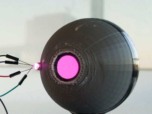
Re the integrating spheres, I can’t comment much more on what we do without getting into trouble, but I can say that something like this works okay:

Also, check out their github for some other interesting stuff.

Re the different guages, yes, they make very little difference regarding the sensor, as you are magnifying the frame to fill as much as possible of the sensor anyway, so it makes little difference as far as the sensor is concerned. The only issue is lighting, as the lighting solution has to be able to illuminate the full frame evenly, and the intensity and ability to do so will vary depending on the guage of the film.

Running the numbers is really worthwhile, but when it comes to sensors, we find that with most of the cheaper ones, their numbers don’t really reflect reality, and with some of the more expensive ones, the numbers are way more conservative, so it gives an idea, but practice tends to be quite different.

As you say, it boils down to how it looks on a calibrated television, but the extra DR and lower noise of better sensors means you can recover detail in poorly shot film, and get a lot more range on adjustments without exacerbating noise or creating banding etc. so the capture process often needs to exceed the final output figures so to speak.

1 Like

I’ve done some more testing with the MC500 and merging two different exposures. Image quality wise I am quite happy. There are still some small artifacts near high-contrast borders, but they are so minor that I think I could live with them (and possibly adjusting the exposures and/or the image merging parameters could eliminate them altogether).

For exposure merging I tried using the linux command line tool “enfuse”, which worked quite well with default parameters I think. There was no flicker whatsoever. It is using a simpler algorithm than other HDR mapping tools, but might work well for this purpose.

However, the framerate of the MC500 might be an issue indeed. It’s capture speed at full resolution is advertised as 5 FPS, but at least with video4linux I have not been able to capture more than 2-3 frames per second (command line or through the java-jni wrapper). So theoretically, with two exposures per frame, close to 1 FPS might be achievable, but currently I have to skip one frame while waiting for the exposure change to take effect, so it’s more like one dual exposure frame per 1.8 seconds (plus the time it takes to advance the film).

Something like 8 hours to transfer one 10 minute reel of film does sound like a lot. I’m using an old projector converted with a stepper motor and it’s probably not a good idea to leave the scanning job unattended (film might break or get stuck or eaten by the machine), so I too find myself at least considering the PGR options. I see there are some new models listed on PGR’s site. Peter, when you are talking about the $300-500 range, is the 2000x1500px Chameleon 3 a good option for the job? Which one would you pick from the cheaper end of the spectrum? EDIT: Would you recommend the USB3 or the GigE version?

2 Likes

If you could implement a wet gate, it would remove scratches and give a better image.

Scratches usually appear when projecting images on a screen because the light is collimated by the condenser lens making the scratch cast a shadow, because the light rays cannot get around them.

In a scanner, condensers are not needed and by using an optical opal diffuser glass immediately behind the film, almost but not touching it, the scattered light can virtually pass around it, making it almost invisible. A light-integrating sphere can also be used if you have room for one.

Jeff

@Big8perf
Some issues about wet gate are, that the chemicals which are used to fill the scratches are toxic, they can cause cancer and are also dangerous to the film material, because they promote vinegar syndrome.
Despite the fact, that the fine detail structure of the scanned film is reduced optically by the wet gate process.
So an image might appear less damaged through the wet gate, but it would also be less detailed and less sharp.

@VitalSparks
In addition to an opal diffuser, an extra scanning pass with near infrared illumination could be applied, to generate a dirt mask by frame. The masks can later on be used to remove dirt digitally.

I can see how this could be employed with intermittent motion, as the dirt pattern would would be identical between the two captures, but do you think this would be successful with continuous motion making two separate passes? How can we be sure the dirt (hairs?) will remain in the same position in each pass? Will the image device need to be modified to remove the IR filter that is often fitted to them? I have little experience in this area.

Jeff

@VitalSparks

Was there already a decision made against intermittent motion?
I know it is always a compromise between cost, speed, quality and stress to the film.
So I would tend more to quality, because in my opinion that could be achieved also at low costs.
I think that the usage of a dirt pass would also be possible with continuous motion, if there are implemented some image analysis algorithms to detect the best match of details, that do not change with wavelength of the
illumination.
However, I would prefer intermittent motion, because it offers much more opportunities to the scan quality.
-A monochromatic image sensor could be used. So there will be no Bayer-pattern, that means a far better filling factor, better anti-aliasing and better usage of resolution to the picture.
-Several illumination passes could be made to achieve a higher bit depth to the image (HDR).
-The exposure time could be extended, to reduce noise caused by the image sensor itself.

Well not every image device has an IR filter and if it has one, it is very often not as effective as one may expect. Most sensors and cameras are still sensitive in near infrared.
That could be checked with a simple test, just take a remote control for tv, push a button and observe the led at the front through your camera on screen
If you see the led shine, then the IR filter is not that effective.

But there are also some brute force methods to remove the IR filter and the Bayer-pattern (and also the micro optics) from the sensor (I would not recommend that):