My Telecine Software

Hi @dgalland,

If we are talking about automatic exposure, in principle we do not ask the camera for any exposure time with the shutter_speed variable. In the PiCamera class, to make automatic exposures, we must set shutter_speed = 0, and obtain the exposure time from the exposure_speed variable

Certainly a variable number of exposures is required until exposure_speed is stabilized. The loop I use in my software is more complicated than simply comparing two successive captures, most of the time 6-8 captures are required.

The Raspberry Pi camera capture functions were one of the biggest headaches I had during software development.

I always take captures in manual exposure, generally with 6 images per frame and a difference of 4 or 5 stops between the fastest and the slowest. This gives a wide range of exposures, enough to digitize any film normally exposed at source. The total process takes about 3 seconds per frame, including the capture, the sending to the main computer, the post-processing and the writing of the final file.
In my next version I hope to reduce this time.

Regards.

@Manuel_Angel
Yes the capture loop is a very tricky piece of code.
Maybe I’m wrong but if I look at your code DS8Server.py I only see a waiting loop in the case of auto-exposure but no waiting loop between successive brackets?
From my experience after setting cam.shutter_speed to a bracketed exposure value you have to wait for 4 frames before you get the requested value in cam.exposure_speed ?

@dgalland

Until now I thought it had a good capture algorithm. With your comments, I certainly now have doubts.
The following snippet comes from the PiCamera class documentation:

exposure_speed

Retrieves the current shutter speed of the camera.

When queried, this property returns the shutter speed currently being used by the camera. If you have set shutter_speed to a non-zero value, then exposure_speed and shutter_speed should be equal. However, if shutter_speed is set to 0 (auto), then you can read the actual shutter speed being used from this attribute. The value is returned as an integer representing a number of microseconds. This is a read-only property.

As you can see, according to the documentation, in manual exposure the variables shutter_speed and exposure_speed must have the same value.

I will do further tests to confirm it.

Anyway, everything can be improved, especially if we talk about software.

… some comments to clarify things:

I checked my old software for Raspberry Pi cams how the fact that the exposure was settled was checked. Here’s the original code:

# has the cam settled to the new exposure?
if int(self.camera.exposure_speed) - int(self.camera.shutter_speed) < 20 :        

   # ok, camera setting time has expired, send the result
   if self.camera.img_type==1:
       # time to send the image!
       if image_size>0:
           self.stream.seek(0)     
           self.counter += 1               
           self.camera.ldrStream.put( 
               (self.camera.img_type,image_size,self.camera.shutter_speed,self.stream.read()) ) 
           self.counter += 1                                 
           utils.logStatus('Output - Image: %d pushed onto LDR queue'%self.counter)

Before that code segment, the desired shutter_speed was set like:

camera.shutter_speed = int(hdr_steps[img_count])

So the sequence of operation was:

  1. set desired exposure time via shutter_speed
  2. read exposure_time while frames are being taken by the camera and wait until both exposure_speed and shutter_speed have the same values, within limits. Then send the image to the client.

Edit: In fact, as I discuss in a post below, that is only partially correct. You will need to wait through 3 to 4 additional frames after this happens to be sure that the image is taken with the exposure value you have requested. See data plot in the post below.

As far as I can recall, waiting only for both values to be approximately equal was necessary because sometimes the automatic algorithms running in the background were not able to get both values equal.

Instead of the above procedure, from my experience, you can also simply wait 5-6 frames; that is the longest time I have encountered under normal circumstances that it takes one of the Raspberry Pi cameras to settle onto a requested exposure.

Note that the above code is old, somewhere around 2018 or so. In the mean time, the Raspberry Pi foundation released lots of new firmware for their cameras. Things might have changed, but as I am no longer using the “different exposure time” approach, I have not checked this.

I am currently running my scans with 5 exposures/5 stops, but only because my tunable light source is not really able to deliver an exposure ranges of 6 stops. I would also work with 6 stops if possible, because with that dynamic range, even the largest contrast you will encounter with color reversal film stock will be properly digitized.

While reducing the number of exposures to a minimum helps you dramatically in scanning time, you loose some other advantages. Let me elaborate:

  1. The dynamic range what a single exposure can cover is limited. Also, the response of the camera (if you are not working with raw data) is non-linear. So if you do not adapt the exposures to the image content (which, as I understand, @dgalland is doing), you simply might miss important image data in the shadows and highlights of over- or underexposed scenes. Also, when working only with a few images, you might notice (due to the nonlinearity of the camera’s response curve) transition zones (banding) in slowly varying intensity gradients of the frame. Have not noticed this with @dgalland’s 3 image procedure, but I have seen this in another Super-8 scanner which was working only with two exposures.

  2. Note that the Mertens algorithm changes drastically the visual appearance of your film material. It needs to do so, as the full dynamic range of a Kodachrome film is impossible to code, transfer and display via existing technologies. But a Kodachrome does no longer look like a Kodachrome - compare the examples I posted elsewhere on this forum.

  3. If you capture the full dynamic range of the film (=5-6 stops) and save the raw LDRs (exposures), you are in principle in a position to process the scanned data into a real HDR video. This involves a totally different approach than the Mertens algorithm and makes only sense if you have a real HDR display for viewing at your disposal. We’re not there yet, but I expect such displays to become available in the next few years. Of course, you can always rescan at that point, but remember that certain film stock fades away… That is the reason I archive every single exposure - which leads of course to a huge demand in disk space. Note that for the creation of a real HDR (not: “Mertens”), you will need absolutely precise exposure values.

  4. Taking several exposures of a single frame allows the Mertens algorithm to average each pixel over a number of exposures, which results in a reduced level of camera noise. This noise reduction scales with the square root of the number of frames taken and is actually also a tiny advantage with respect to working with raw frames.

  5. Lastly, I would recommend to store the output of the Mertens algorithm as 16 bit per channel image, not a 8 bit per channel image (if you have the disk space). While this might not be noticable under normal circumstances, the increased color resolution might help you in the post production. daVinci Resolve has no problems working with 16 bit per channel images.

welcome to the club! :smile:

2 Likes

@dgalland
I have been doing tests and indeed, I have to admit that I had the wrong idea.
Experimentally I have been able to determine that the variables shutter_speed and exposure_speed do not equalize until the second capture. In the capture algorithm I have added a loop to take 2 false shots before the final capture.
Obviously this will mean a certain increase in the capture time. I hope it is not much, the false shots are made with a very low jpeg quality parameter, in order to make the size of the images small.
At the moment I cannot appreciate the impact on a real shot. Where I am I do not have the real machine and I am doing the tests on a simulator that uses a Raspberry Pi 4 as a client instead of a PC.
Thanks for the warning

@cpixip Impressive explanation. Thanks again.

@cpixip
I think that there is no perfect equality between requested shutter_speed and obtained exposure _speed because the exposure_speed must necessarily be a multiple of the scan time of a line of pixels of the sensor.
@Manuel_Angel
In the picamera documentation it is important to read Misconception #1 and #2 and understand that the Pi camera is not a DSLR but rather a video camera.The camera sends a continuous stream of images at the requested framerate, that’s why a requested shutter_speed change will only be effective a few frames later.
So you have to ignore at least two or three frames after a shutter_speed change.
This slows down the capture a lot, that’s why I limit myself to 3 exposures (I don’t think that the change of jpeg quality will change anything because the jpeg processing is done later in the ISP and does not intervene in the exchange between the camera and the GPU of the PI)

Of course the shutter_speed modification must be done with exposure_mode=‘off’ otherwise AGC algorithm will compensate by changing the analog or digital gain. These gains must absolutely remain close to 1.

There remains the question of auto exposure. I really think that for amateur films with scenes of very variable luminosity, auto exposure allows to have a good starting point for the median image before doing the HDR. It can be seen as an optimization. What’s the point if the image is very dark to make 6 exposures, most of which will be just as dark? I prefer to let the auto exposure play and then make my three exposures.

In this case HDR it’s more complicated because you have to switch back to exposure_mode=‘off’ to get the over and under images before switching back to exposure_mode='on" to come back to auto for the next image (refer to my code for implementation details) In this mode with all the necessary waits I capture at about 2s per frame.

yep, that might be. It’s been years since I wrote that code.

Just for fun - here’s a data capture of mine from the v1 camera dating from April 2017 (that was the time I was investigating this):

The green crosses indicate a certain camera.shutter_speed (precisely: the value plotted is camera.shutterspeed/100)) and the red crosses the corresponding camera.exposure_speed (precisely, camera.exposure_speed /100). Note the one image lag between camera.shutter_speed and camera.exposure_speed.

The blue curve is the actual recorded image intensity and should ideally be following the shutter_speed setting. Clearly, this was not the case in 2017, and even worse, the behaviour between a step-up in exposure and a step-down in exposure was different. Whether this is still the behaviour of the Raspberry Pi foundations ISP I do not know - most probably, this has not changed too much.

Just for the record: the fact that camera.shutter_speed being equal to the camera.exposure_speed seems not to indicate that the exposure has really setted to the requested value. I think in the end I decided to wait simply additional 3 or 4 frames after this happened. So my above comment about my code was only half right (sorry, but this was all a long time ago…)

Also, for the record, this is the behaviour of Raspberry Pi hardware when the camera is operated in capture_continuous mode (that is “video” mode). When operating in “picture” mode, the camera in fact takes at least two frames - one for getting the current image statistics, and the second one for real. That’s why it takes with the Raspberry Pi cameras two seconds to take a photo with one second exposure time (but, that’s a different story).

You certainly have a point here. However, from my experience, quite a few scenes in a normal Super-8 movie do show a dynamic range within a single frame which exceeds what you can capture with three different exposures.

The following (A) is a rather typical example of a standard Super-8 frame

and this one (B) is also comparable:

If I had worked only with three exposures (that would be the upper row of images in the examples above only), in (A) the face of the man in the center of the image would have been ill-defined. (B) shows a more pronounced case, also with sub-optimal image detail in the face of the man as well as on the right shoulder, where the details of the cloth starts to disappear into the darkness.

Given, I could have worked with three captures and spaced them further appart than one f-stop, covering a larger exposure range in this way. But even than I would only sample those very dark areas in the brightest image exposure with a section of the camera transfer curve which is definitely non-linear (the knee of the S-curve). The same argument goes reverse for the highlights in the darkest image (the bow of the S-curve).

Since I was able to capture five different exposures within about 2.5 seconds per frame, I went along that way for some time. Nowadays, my system uses instead a tunable light source for establishing the different exposures and the HQ camera I am using operates just with constant settings through the whole capture.

1 Like

New version of DSuper8 software.

In this version the handling of HDR images has been improved.

To complete the Mertens algorithm I have taken into account the indications of @dgalland and of @cpixip . Thanks to both. The dynamic range of HDR images obtained using the Mertens method has improved markedly, although the contrast has certainly decreased.

The Devebec algorithm has also been improved and gives good quality results with 6 photos per frame.

I have also taken into account the suggestion of @Ral-Film whom I thank for their contributions. Now it is possible at any time during the capture the activation and deactivation of the storage of the bracketing images. The exposure time is found in the EXIF data for each individual image.

Also minor bugs have been fixed.

Hope everything works fine.

Greetings to the forum.

DSuper8 Wiring Diagram.pdf (45.5 KB)
DSuper8-Server.zip (14.2 KB)
DSuper8-Client.zip (786.9 KB)
Instructions.pdf (33.8 KB)

2 Likes

@Manuel_Angel
I looked at your wiring diagram and I don’t understand the interest of the ULN2003 circuit in addition to the TB6600. The 3.3V GPIO signals of the PI can easily control the inputs of the TB6600 ?

Hi @dgalland,

The driver based on the TB6600 chip uses opto-coupled inputs. To correctly bias the input LEDs, about 15 mA each is needed.

If we connect the pins of the GPIO port directly to the inputs of the driver, it does work, but in my opinion this situation is dangerous for the Raspberry Pi. We risk damaging the GPIO port from excess current. 15 mA is a very high current for the port pins.

The Darlington transistors of the ULN2003 chip have a very high current gain (more than 500), so that with an input current of less than 1 mA, we can obtain an output current of 500 mA. The GPIO port works with a minimal current.

Apart from this, we get two additional advantages:

  • The lighting can be controlled via software, using the transistors of the ULN2003 chip as a switch.

  • We avoid the necessary circuit to power the driver’s LEDs at a voltage lower than 5 V.

I leave a link to an interesting page with a lot of information about the GPIO port. Among other things, they talk about current limits.

Regards.

Hi everyone,
I have done some tests with a very contrasted image to compare the results of the HDR Mertens and Devebec algorithms.
The starting images have been exactly the same.
Let each draw their own conclusions.

Bracketing images:

Mertens method:

Devebec method:

Regards

1 Like

@Manuel_Angel - can you elaborate a little bit more how you applied the Devebec-method?

The background of my question is the following:

The Mertens method is “just” a way to combine the best looking parts of a series of exposures into a single image. It uses normally three different parameters to estimate this “best looking” criteria for each image part. Usually, these are measures of well-exposedness, saturation and local image contrast. Depending on how you set these parameters, you will get slightly different looking results. While the output of the opencv Mertens implementation is actually a float image (even with negative pixel values), the intention is nevertheless only to map a stack of images covering a high dynamic range into a low dynamic range image (LDR - usually just 8 bit per color channel).

The Devebec method is actually something very different. It creates out of the different exposures of a scene a real HDR (actually, a radiance image). To do so, the method needs the exposure information for each of the input images. It than uses that information to calculate the camera’s response functions. Once these response functions are known, it is possible to transform the input images into the HDR space. That is usually the output of the Devebec algorithm.

Only after you have obtained the HDR image, you are in a position to re-transform this HDR image back to a LDR which you need for transcoding/transmission/display on standard hardware. This process is called “tone-mapping” (different tone-mapping algorithms are tested/displayed at the end of this page and this page, for example). Tone-mapping is separated from the Devebec algorithm, it’s part art and part science, and there are a lot of scientific papers out there about that subject.

From my experience, I would have expected quite different results from your input images. Usually, if you normalize the Mertens output, it kind of just looks ok. If you do the same with the HDR the Devebec algorithm outputs, you are usually getting a very dull image - especially in high contrast cases.

Clearly, your Mertens result looks duller (less local contrast) than the Devebec image (where it is unclear what type of tone-mapping was applied). I would have actually expected just the opposite results, similar to what is described on this page.

Also, in your input image sequence, there’s a magenta color tint noticeable in at least the three brightest images - which does show up quite well in the Mertens output, but not so much in the Devebec result.

What is surprising is the magenta cast on the last three images. This magenta is going to be in the Mertens merge, it’s absolutely normal.
Are you sure you are in awb=‘off’? You should manually check that this magenta cast is normal at high exposures and also change the color gains and try the merge again.
Why the magenta doesn’t show up in the merge debevec is another question. It looks like the merge debevec is doing a white balance?

@cpixip
First of all, I must admit that I am by no means an expert on the matter.
To write the image processing software in order to obtain a final HDR image, both with the Mertens method and with the Debvebec method, I have relied on the information available on the Internet, among others on the pages you have indicated.
In my previous implementation of the Devebec algorithm, I got very poor results, not because of bad programming, but because of misconceptions about how the RaspiCam works.
Basically the software does the following:

  • The server takes one after another the images requested in the GUI, taking into account the number of images and the number of stops.
  • The captured images along with additional information (among other things the exposure time) are sent to the client as they are obtained.
  • The client software stores the images in a list and the exposure time reported by the camera in a matrix. My mistake consisted in saving incorrect data in the matrix of exposure times that did not correspond to the real ones used by the camera. I think the problem is now fixed.
  • Once all the images have been received (6 in the case of the example), they are processed with the requested algorithm:

Mertens (pseudocode):
blender = cv2.createMergeMertens ()
img = blender.process (Image_list)
The next line thanks to your contribution and that of @dgalland:
img = cv2.normalize (img, None, 0., 1., NORM_MINMAX)
img = np.clip (img * 255, 0, 255) .astype (‘uint8’)

Devebec (pseudocode):
We get response function from the camera
calibrateDebevec = cv2.createCalibrateDebevec ()
responseDebevec = calibrateDebevec.process (Image_list, exposure_time_array)

Fusion Devebec:
blender = createMergeDebevec ()
hdrDebevec = blender.process (Image_list, exposure_time_array, responseDebevec)

Tone mapping is applied. In the example, Reinhard has been used
Applied parameters:
ReinhardGamma = 1.2
ReinhardIntensity = 1.8
ReinhardLight = 0
ReinhardColor = 1

toneMap = cv2.createTonemapReinhard (ReinhardGamma, ReinhardIntensity, ReinhardLight, ReinhardColor)
img = toneMap.process (hdrDebevec)
img = np.clip (img * 255, 0, 255) .astype (‘uint8’)

That is the whole process. It only remains to resize the image and save it to a file.

@dgalland
In effect, there is a dominant magenta that for the moment I do not know its origin. The white balance I have not modified. The awb parameter is set to off and the blue and red gains are fixed. I have to keep investigating. This is the never ending story.

Thanks for your contributions.

@Manuel_Angel - ok, things are getting clearer…

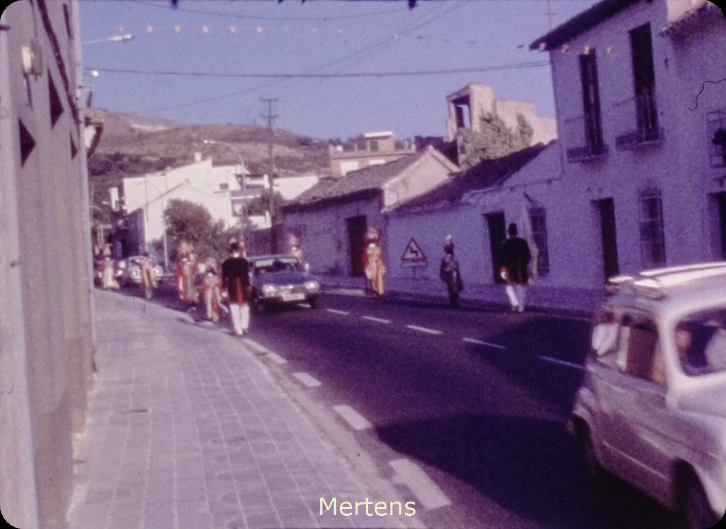
When you do in the Mertens path the following

img = cv2.normalize (img, None, 0., 1., NORM_MINMAX)
img = np.clip (img * 255, 0, 255) .astype (‘uint8’)

you basically map the pixel with the lowest value onto the 8-bit value 0x00, and the pixel with the highest value to the 8-bit value 0xff. That is ok, but it is sub-optimal.

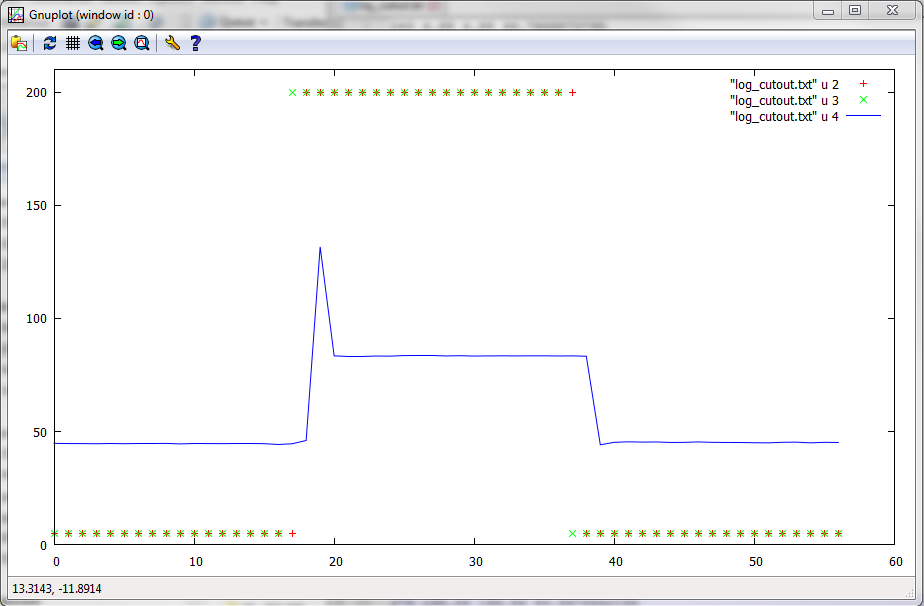
The reason is that sometimes there are only a handful or even less pixels with these extreme values - you fare usually much better if you use a code similar to

minimum = np.percentile(img, 1)                                 
maximum = np.percentile(img, 99.0)
scaler = 1.0/(maximum-minimum+1e-6)

img = scaler*(img-minimum)

img = numpy.clip(img * 255, 0, 255).astype(‘numpy.uint8’)

This code disregards the darkest and brightest 1% of the pixel in the frame and gives you usually better output results. You might want to play with the percentages - even 10% (that would be 10/90 instead of 1/99 in the above code) might be ok. Just do some experiments.

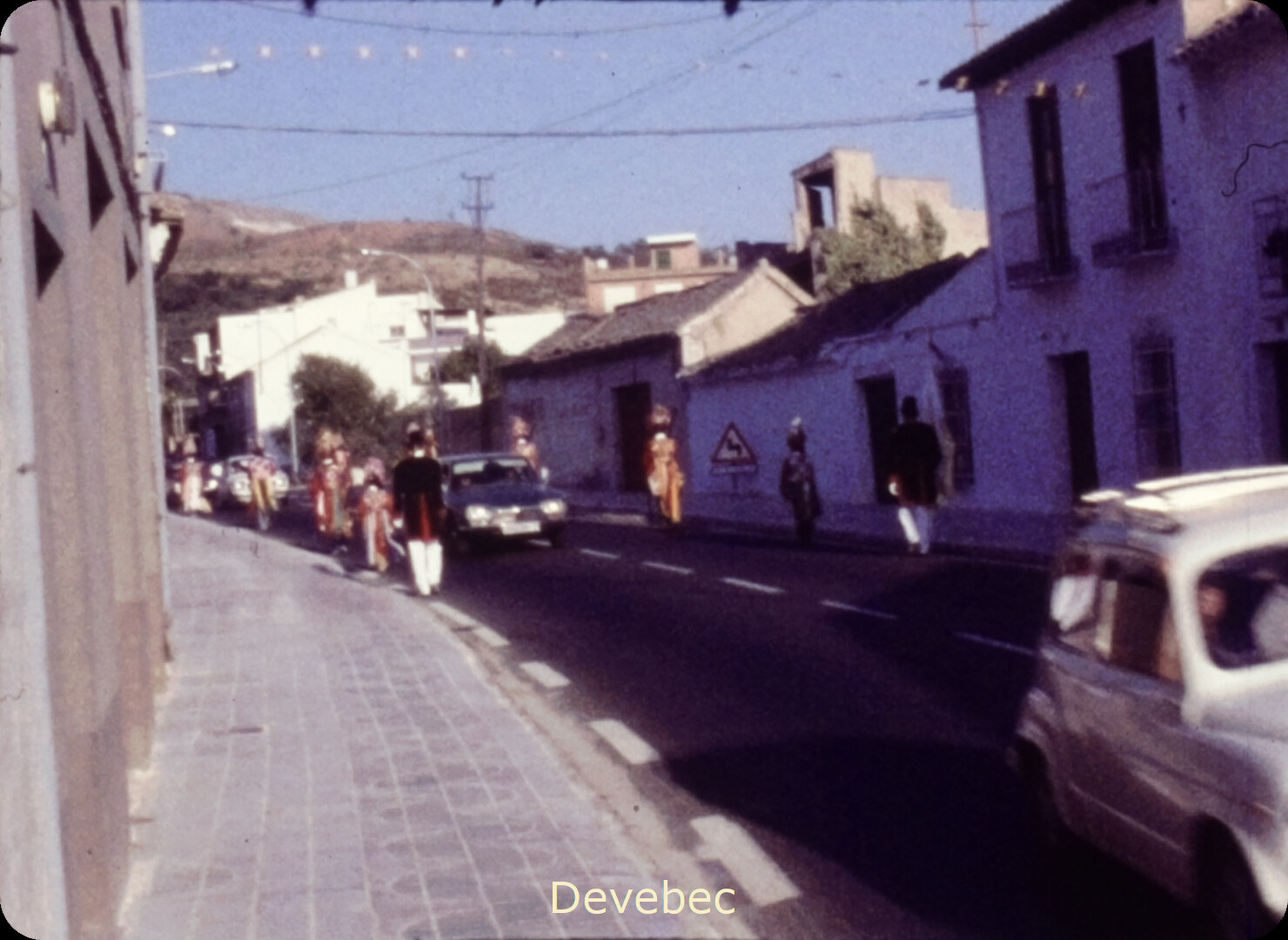
Now, you are treating the Devebec totally different, using your old

img = np.clip (img * 255, 0, 255) .astype (‘uint8’)`

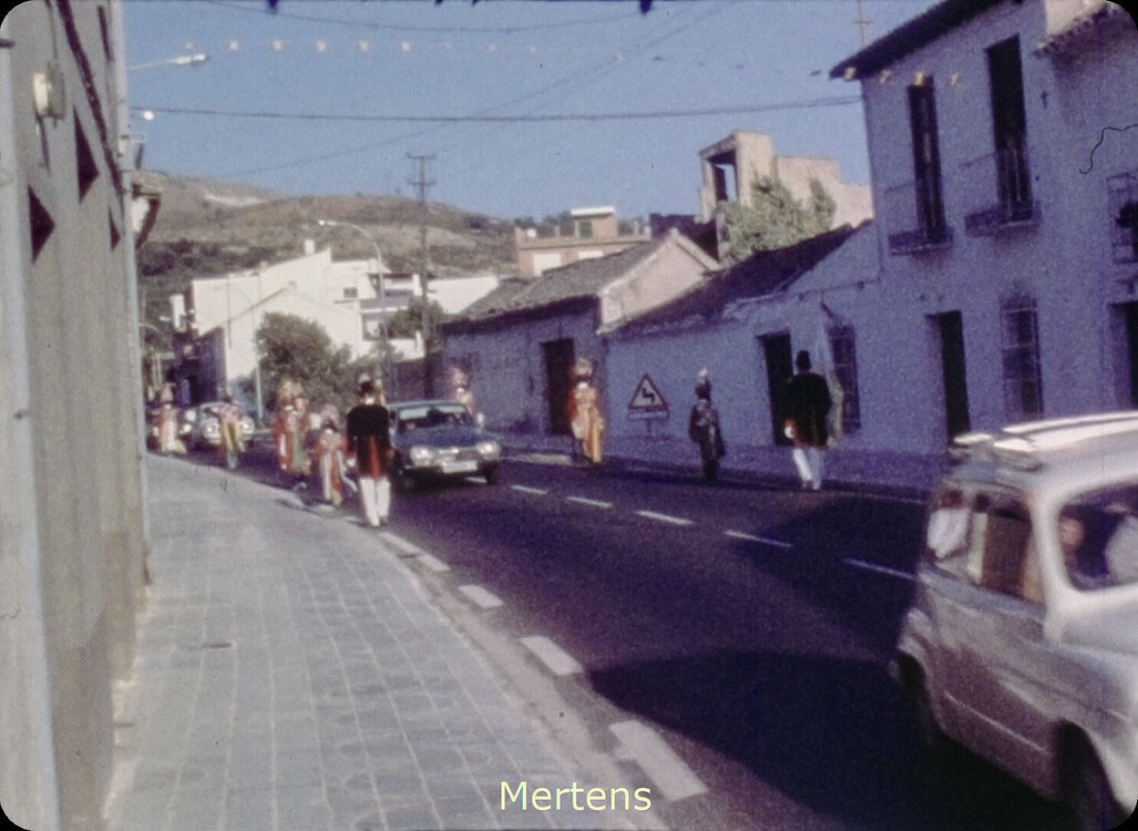
processing step (after tone-mapping). In case the tone-mapping does not map into the [0.0:1.0]-range, you will cut off highlights and dark shadows. I see actually indications in your result that this is happening. Compare the texture of the bright house left-center in your two results. It is certainly better defined in the Mertens result than in the Devebec one.

Furthermore, through the Reinhard tone-mapping, you are increasing the gamma of the image (ReinhardGamma = 1.2), which leads to more contrast in the Devebec case - try to compare with a run where ReinhardGamma = 1.0 and make sure that you are not clipping the result of the tone-mapping.

Finally, setting ReinhardColor = 1 asks the tone-mapping algorithm to independently process the three different color channels, leading to a sort of auto whitebalance, reducing in turn the magenta cast you have in your input images. That’s the reason why the Mertens result shows much more magenta. What happens if you set ReinhardColor = 0?

On closer inspection of the input frames, it seems that all do have a magenta cast. This indicates that your red and blue gains are too high for this movie.

1 Like

Good point @cpixip , I reread the original article of Reinhard and indeed it is said to proceed to a kind of white balance to make disappear a possible strong color cast! This is the disadvantage of these algorithms with multiple parameters whose effect and choice is not always very clear.
So here is the Mertens image with some more green:

@cpixip is right to consider the very bright white wall of the house on the left.The HDR processing will recover the details in the light parts and avoid burned whites, for me this is more important than the lightening of the dark parts.

5 Likes

Hello Manuel,

thanks for all your work.
I am currently not at home therefore I am not able to check out your new SW version.
As soon as possible I will try your SW (in about 2 weeks) and let you know about the results.
Thanks again I really appreciate your work.
Best regards Ralf

@dgalland, @Manuel_Angel - may I also remark that @dgalland’s color-corrected image shows also more detail in the darker areas than the Devebec result…

(for example the street/house wall left to the bright house or the windows on the right in the shadow)

For what its worth, thinking I had all the software installed properly, I did encounter this kind of error
Could not load the Qt platform plugin “xcb” in (…) even though it was found

After a couple days, I did resolve the issue by installing an older opencv 4.1.2.30 and removing 4.5.3.56.

IF you update your instructions, maybe list of required modules AND their version number. Could be helpful as modules may be updated but may later cause issues.

Oh, and also when click the step forward it appears to only microstep and stepping backwards appears to microstep AND then one full revolution (1 frame). If I press either continuous movements buttons, it just vibrates until I stop it. I’m guessing that I’ve a pin mismatch in the config maybe? Which leads me to I am using the DRV8825 (I also have a TB6600). I’m assuming either of these should be fine, but maybe the wiring is different.

HI @Wheaticus,

Sorry for the mistake and inconvenience it caused you.

I have to tell you that it has never happened to me. I know that there are other people who also use the DSuper8 software and have never reported errors of this type to me.

I don’t know how you have installed the Python modules and especially opencv. In the instructions I recommend using the Python Anaconda distribution. Specifically, the opencv module is not installed by default with the distribution, but it can be installed later as follows:

We open a console (both in Linux and Windows) and execute the following commands:

  • We update the distribution: conda update --all
  • We install opencv: conda install opencv
  • We delete unnecessary files: conda clean -t
  • List the installed modules: conda list

It is assumed that the version installed by the distribution is the correct one to work without problems with the rest of the Python modules.

I do not know or have tested the DRV8825 driver. In my device I use a driver based on the TB6600 chip. With the latest version I have published the wiring diagram that I have been using without problems for quite some time.

It is normal that when a rewind order is given in the motion of the film, the last step is to advance one frame. This behavior is intentional. It serves to avoid the small misalignment of the frame that would exist if the last movement had been backwards. When the last movement is forward, the error is eliminated.

Regards.

1 Like