Pi HQ Camera vs DSLR image fidelity

As I finished my transfers I did not modify my yart application (maybe one day?) but I still do some RPI5/HQ/Picamera2 tests
So here are my thoughts on Rolf’s very complete presentation as well as Manuel’s posts

Multi-exposure vs DNG
Yes it is possible that DNG capture can replace the merge mertens.
However, multiexposure had something magical about it by automatically adapting to the film’s brightness variations, no need to decide on an exposure
Note that the DNG conversion in picam2 is done by a third-party 100% python library
It is unfortunate that the PI foundation does not take over this library by optimizing it

Client-server or not
The client-server design with GUI, processing and saving frames on a PC was essential with a PI4
It is less necessary with a more powerful RPI5 and a fast SSD disk
However, it remains easy to use
To keep?

Motor control
As noted, the GPIO programming is completely different with the RPI5
It is not possible to use a hardware PWM such as the pigpiod library and a software PWM is not satisfactory
Using an arduino to control the motor is possible but it induces greater complexity
Hoping for software changes?

Post processing
More and more people are using Da Vinci since the free edition is already very rich in possibilities
But it remains manual and tedious. For my part I remain faithful to avisynth scripts
There is an initial investment but then everything can be automated
I proceed in three steps deshake, clean, adjust with intermediate loseless files

I launch my scripts and the next day it’s finished for all my films §
For example to launch the clean step on the files of the deshake step
doall clean deshake

The only thing left to do in the final editor is the color correction for certain scenes

Note for cpixip
No need for virtualdub to run an avisynth script ffmpeg is enough and it is easily automated

ffmpeg -i dostep.avs -c:v utvideo -pix_fmt yuv422p -colorspace bt709 -y %output%

and the same for encodings
ffmpeg -i %input% -c:v libx265 -crf 28 -preset medium -vf format=yuv420p -y %output%

ffmpeg is not always easy to understand in its options and arguments but it is really a powerful tool

The result deshake->degrain->correct

5 Likes

Well, I tried the RP5/fast SSD setting before I tried the RP5/LAN/Win-PC combination. Both have their merits.

The RP5/fast SSD combination is a self-contained system, or at least, it could be. That is, everything is handled during scanning on the RP5. In my case, I opted to setup/preview the data on the Win-PC, as I could do this by re-using existing preview/setup software. I tried to run the same software on the RP5, but it makes things too slow for my taste: the RP5 is touching its speed limits.

For example, I occationally use RawTherapee for checking the intensity range of the currently scanned frame. Specifically, whether the shadows and highlights are digitized well enough. Starting up RawTherapee on the RP5 can be done, but it is slow.

I tried this setup (RP5/fast SSD) first, mainly because I was not sure that I could transfer the huge amount of data sufficiently fast between RP5 and Win-PC. In the end, that approach (RP5/LAN/Win-PC) worked however amazingly well.

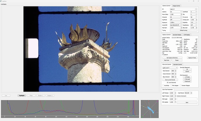
I capture not only the raw file, but also what libcamera/picamera2 calls “main” profile. Both are send via LAN to the Win-PC. The “main” profile file is used for displaying and analyzing the current frame on the PC, for example, a histogram and a vector display is derived from the “main” data.

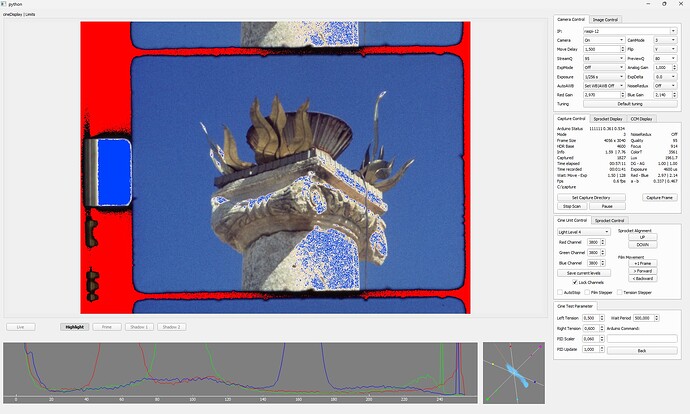
Remember: the “main” profile is very close to the image you will get once you load the raw file into DaVinci, as it is using the same color matrix (CCM) and rec.709. I have also various analysis tools build into my software (running on the Win-PC). For example, I can zoom into any portion of the frame, or I can display under- and over-exposed image areas, like here:

These additional analysis functions are the reason why the RP5 kind of lacks the required performance. The raw data is simply written directly to disk by the Win-client.

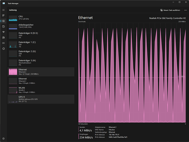
I was afraid that the shear amount of data would be too much for my local network, but it turned out to be no problem. Looking at task-manager:

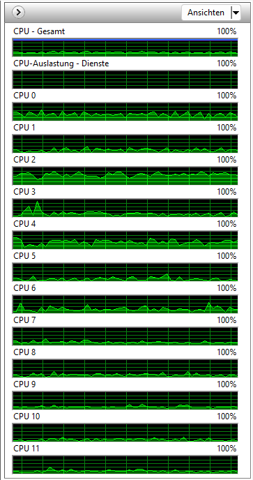
one sees that indeed the “Ethernet 2” connection is quite heavily used. In fact, every 1.5 seconds, there’s a data peak delivering 234 MBits/s. The 1.5 seconds are the interval at which the frames are scanned. As one can see, the CPUs are nearly idle, at about 30%. My Win-PC has 12 cores, and while scanning there is plenty of computing power still available:

The raw data is stored by the Win-client on disk “C:” - if you look at the above task-manager display, it’s barely in action. Typically, only 2% resource is used. So I have no problem working on the Win-PC with other tasks while doing the heavy lifting of a scan. In fact, I am writing this post while I am running a scan.

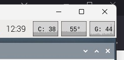
Finally, looking at the RP5 doing the actual scanning, we see this here:

grafik

So the RP5 needs during the scan only about 40% of its CPU resources, and it stays at a moderate CPU-temperature of 55° (my RP5 uses a cooling fan). One note here: the steppers are driven in my setup with a Pico, not directly via the RP5. The Pico also monitors the film tension independently, freeing again resources on the RP5.

So, while a self-contained RP5 solution has its merits (it could be self-contained, for example), I personally prefer to use the client-server construction. Mainly for easier resource management, but also because I can throw in some analysis functions easily, by just adding code to my Win-client. Also, I have my raw files already on the machine I am going to do post production - no need to unplug the SSD from the RP5 and mount it on the Win-PC again.

4 Likes

I have been rather enjoying these writeups. Thanks for taking all of the time to get your methods down clearly. I know it can take quite a while just to describe the steps!

I was just about to tackle this sort of pre-stabilization step in my own pipeline. I do a coarse crop based on the sprocket hole, so that side of the image is quite steady but the opposite side does a little 1-2 degree wobble at a frequency that makes me think it’s related to the shape/orientation of plastic reel somehow. (Maybe this is the answer to why some machines have such a long film path with so many extra rollers…)

In any event, I remember seeing a video of yours—quite recently, I thought?—with the frame edges and sprocket hole visible that were absolutely rock solid to sub-pixel accuracy… but after searching through the last six months of posts, I can’t seem to find it again. (Maybe you’ll know which clip I’m talking about?)

If it isn’t too much trouble, I’d be curious to hear about the algorithm in your own software that you’re using for that initial alignment (potentially in a new topic since it’s a little off in the weeds for this image quality discussion). I just remember it being quite impressive!

Does it only use the sprocket hole? Or does it try to find the frame edges/corners somehow? What sort of feature detection is going on?

I have a few wacky ideas that I haven’t tried yet but I don’t think any of them would give results as good as yours already are, so maybe I can shortcut the process by following in your footsteps. Even if you don’t have the time for a detailed write-up, I would be grateful for just a few lines that might get me started down the right path. Thanks!

Well, might be that you are looking for this thread - which was posted 4 years ago. Basically, I am still using this algorithm. It’s not too precise, as it works only with integer shifts, on a zoomed-down version of the sprocket area. I think the current code can be downloaded from this github page.

(Haven’t made much progress during the past days; the kid bestowed us with Covid…)

Your explanation made it perfectly clear :ok_hand:

pre-stabilization step

What are the benefits of doing this? I assume you get a more “true” representation of the original material since DaVinci would use a bigger portion of the frame to stabilize and then kind of “overdo” things? But for that you need convert the frames into a format other than dng, and in the end you’d want to stabilize the footage itself anyway…?
(Actually, I think I’m just impressed with the fact that you can decide on a color grade this early in your pipeline. :sweat_smile: For the few (projector-recorded) films I’ve edited I had to take breaks and come back with fresh eyes a couple of times. Although you probably don’t lose anything when working with tiffs and can do the same later on…)

I made an attempt at using DaVinci’s Tracker (within Fusion) to limit stabilization to the sprocket hole area, but my PC surrendered during playback. But if you have a more powerful machine this might be an alternate way to do some sort of pre-stabilization?

Well, the design of my scanner does not assure that the sprocket hole ends up in a fixed position for each frame. You would not have this problem if you would use an old projector for this - which ensures (if designed correctly) that each frame’s sprocket position ends up in a fixed position.

In the end, with my scanner, the frame kind of oscillates up and down in a periodic fashion, locked to the sprocket wheel advancing the film.

In principle, this periodic up-and-down motion could be handled by using one of the many stabilizers DaVinci offers. Some people are actually doing this. I never managed to get this to work in an easy way, so I wrote my own software. Also, most of the time, there was still some residue of this up-and-down motion in the stabilized footage. And that spoils the main stabilization I am interested in: reducing the camera movements of S8 material which was mostly recorded without the use of tripods or so.

In fact, the camera tracker I was suggesting in an above post does not “overdo” the compensation, but does “under-do” it. The simple reason: you do want to keep that main characteristics of your footage. If you want to see what the stabilizer is capable of, simply click on the “Camera Lock” checkbox and watch the result on a scene with large panning or zoom motion, for example. You’d be surprised.

Summarizing: I have two very different motions I want to get rid of. An up-and-down motion caused by my bad scanner design, and the motion induced by mostly handheld S8 cameras. It’s way simpler to treat these different motion components in different processing stages than trying to compensate both in a single process step.

Well, I am still trying to figure out the best way here; what I described above is more on the simple side, with difficulties of color definition if highly saturated colors are involved. And yes, you could already color grade the .dng-files. Many people in video production are doing just this. Or, you could use 16-bit linear encoded .tif-files, with no loss of color resolution at all, for intermediate results. Or, as I did describe above, use 16-bit rec709 encoded .tif-files, with some unimportant loss in color reproduction, but an easier setup in case of DaVinci. Again, I am still experimenting here what might be the optimal way for my work flow.

2 Likes

I’ve run the perforation tracking test several times in DaVinci Resolve, and it’s very effective: the perforation remains perfectly stable, which is great.
However, the rest of the image shows slight parasitic movements that weren’t there before this process.
The reason is quite simple: the camera, film, and scanner all have small inaccuracies, meaning that stabilizing only the perforation introduces unwanted movements into the image.
Personally, I believe stabilizing the image directly, without focusing on the perforations, produces better results. However, I’m not sure if this can be done reliably with a scanner that only detects the position of the perforations.

… it might be of interest to the forum members which tracker you specifically used and in which way you set things up. There are many different ways to stabilize things, like using the trackers available in the “Fusion” page, and various other tracking options in the “Color” page (Cloud- or Pointtracker, etc?) Do you mind giving the audience of this forum a little bit more information?

Well, indeed, that might be the case. A tell-tale sign of a bad sprocket registration in camera of S8 footage is when you notice the width of the little black border between frames changes height from frame to frame.

However, another thing one needs to mention: if you are using the sprocket neighbouring the frame you want to stabilize, you are doing it wrong: there is a two frame difference between the sprocket used for registration and the frame being exposed in the camera. Of course, you can find the same distance between sprocket and film gate in any S8 projection system as well.

Generally, these subtleties do not matter at all. S8 footage was typically shot hand-held, that is, no tripod or other camera stabilization was used. And even the most steady hand introduces camera shakes which are typically much greater than the movements introduced by sprocket jitter.

My own S8 camera, a rebranded Chinon camera, had in fact a very bad sprocket registration. Here’s for fun an example (that was actually shot while the camera was on a tripod):

Obviously, sprockets are not aligned at all with the camera’s frame in this short clip. Between the two top frames, a tiny black border is visible (which is more or less the usual case), but between most of all the other frames it’s gone. In one of the frames (second frame from below), the camera transport even failed completely, leading to a double exposure in this case. Followed by a rather large black border gap just before and after the lowest frame.

So the above mentioned variation of the width of the little black border between frames is substantial. Only a frame-based (content-based) registration can get rid of that stuff.

Doing only a content-based registration turned however be too challenging for DaVinci in my case (which is a special case - my scanner does not use the sprocket hole for alignment, so the sprocket does a little dance in the original scanned data). I get better results with a two stage process: first, sprocket-align the footage, second, do a camera stabilization based on the frame’s image content.

2 Likes

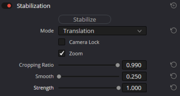
To stabilize the footage, I experimented with DaVinci Resolve’s Fusion page. I selected the horizontal side that showed the least irregularity. Nothing special

That’s a great point—I hadn’t thought about the offset between the two images. I had spent a lot of time modifying my scanner to capture the perforation as it passed in front of the camera. In hindsight, it was a bit misguided, but your comment has made me realize that I should reposition the laser pointer and align it with the second perforation hole. I don’t expect dramatic improvements, but it should result in a bit more accuracy. :+1:

That being said, I don’t use DaVinci to stabilize the perforation directly.
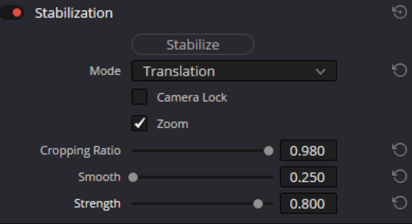
On my scanner, I prefer to capture just the image, excluding the perforation, with a small black border at the top. After that, I apply stabilization shot by shot in DaVinci, similar to what you’re doing.

image

If there are any high-frequency jitters left, I run a second stabilization pass using very low values.

image

The resulting cropping is minimal, and the “lost” image is far smaller than the native cropping on older projectors.

2 Likes

I’m getting a little closer to actually scanning something again and noticed something you might have an explanation for. (This is about the Pi HQ Camera at full resolution).

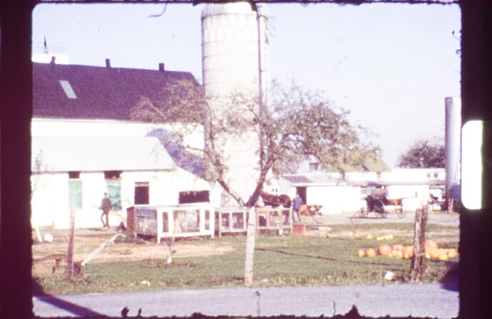
I’ve scanned a few accidentally completely overexposed frames like this:

(Although I think they didn’t look overexposed in the preview… When I open the DNGs I’ve recorded, their default development always looks overexposed - no matter which viewer. Metadata is true to what I set up, though, so I guess all the data is there…?)

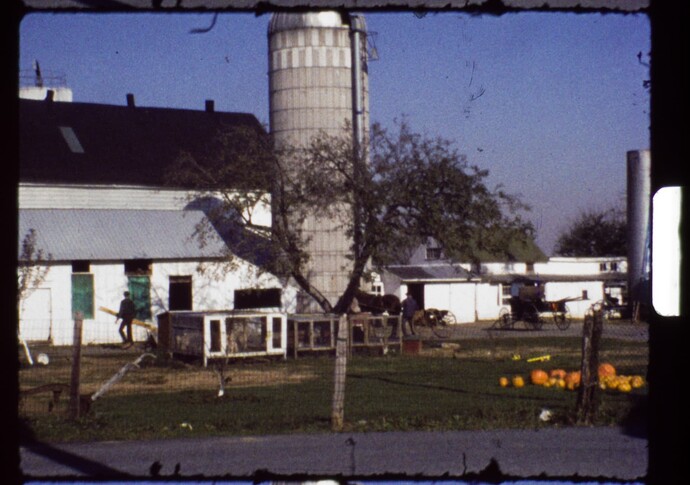
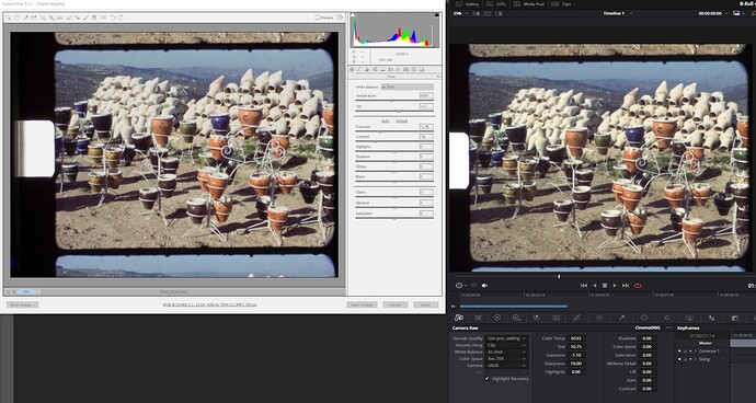
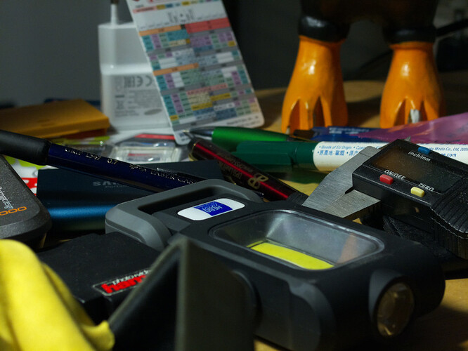
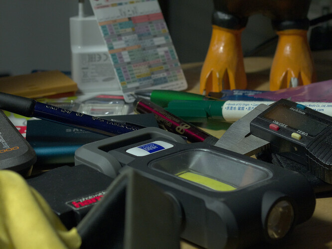
Anyway. I went into Adobe Camera Raw (9.11, the one I use with the old Canon), and dialed exposure down to -3.00. This is the result:

Then I did the same in DaVinci.

With this result:

What did I miss? The DaVinci frame looks depressingly dim. Any additional setting I might need to look out for?

1 Like

Well, I have my guesses. But without the original raw scan, I can only guess.

First: you did not scan overexposed. If you would have, there would be no exposure setting which would enable to recover the burned out highlights. Clearly, both Adobe Camera Raw as well as DaVinci were able to do so. That observation is matched by your comment “they didn’t look overexposed in the preview” - well, simply because they weren’t.

The culprit is your development software. Citing you again: “Default development always looks overexposed - no matter which viewer.” Well, that might be caused by a bad .dng-setting.

In order to understand the following argument, we need to understand what a raw .dng-file actually is, simply speaking. In the middle section of this post I listed all the metadata information of .dng-file created by picamera2. Have again a look at that list of tags.

The intensities (values) the sensor is recording are linear in the light intensities of the scene. Specifically, the HQ sensor works at 10 bit or 12 bit. In your case, “full resolution”, it should be 12 bit dynamic depth. Now, a pixel looking at a very dark image area will have a very low value - but not zero as one might expect. Which value corresponds to “absolute darkness” is actually encoded in the .dng-file by the tag Black Level : 4096. In fact, that value is only true when using a RP5/HQ combination. If the .dng would have been created on a RP4/HQ combination, it would actually read Black Level : 255.

The reason behind this is that each pixel value (well, actually each pixel’s color channel value) is encoded as an integer. The 12-bit range would start at 0, up to 2**12-1 = 4095. This later value is the maximal intensity one can get out of the HQ sensor - it will be the value you receive in a totally overexposed part of a scene. The maximum intensity your “.dng-viewer” can expect is also encoded in a special tag: White Level : 4095.

While the RP1-4 simply pipe this value from the sensor into the .dng-file, the RP5 works differently. It scales the 12-bit range of the sensor into a 16-bit range. That’s why the tags of the above .dng-file have different values: Black Level : 4095 and White Level : 65535.

Whatever is used to view a raw .dng-file, this piece of software has to take these two tags of the .dng-file into account. If that is done properly, your image should pretty much look like your preview image during capture. Why this does not work in your setup is difficult to analyze.

If you decrease the exposure in your .dng-development program, you are bascially shifting the maximal intensity towards higher values. So intensity values which were clipped before become visible, and that’s what you have encountered in Adobe Raw as well as in DaVinci. If these areas would have been overexposed already at the sensor level, these areas would have stayed burned out. Because they do show image structure, they are not overexposed.

You want to make sure that your exposure is such that even the brightest image areas are well defined and slightly below the White Level maximal value. You should be able to check this in any of your “.dng-viewers” - how, depends on your software. Let me sketch how it can be handled in DaVinci.

My scanner is setup in such a way that the sprocket area (or: alternatively, the empty film gate) is mapped to the maximal possible pixel value, that is White Level : 65535. If I load a frame into DaVinci, it looks similar to your experience - washed out.

grafik

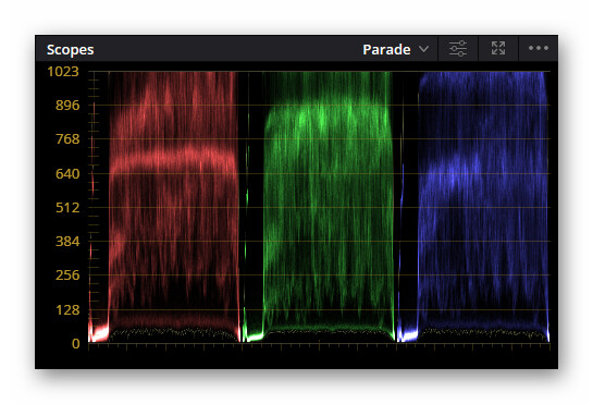
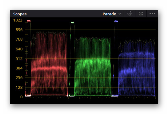
Well, I do not care at all. Looking at the “Scopes → Parade” viewer, the verdict is clear:

grafik

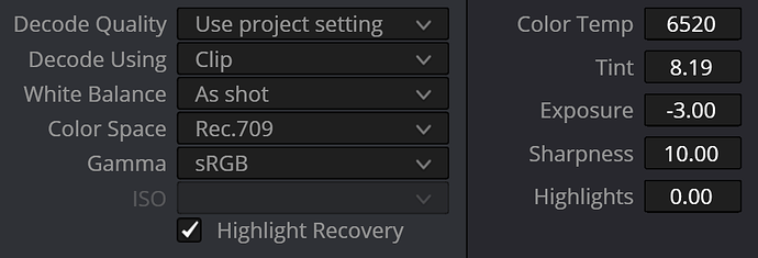
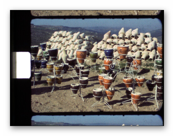
This image is not scaled properly. Decreasing the “Exposure” value in the “Camera Raw” tab from 0.00 to -1.62, I end up with the following image:
grafik
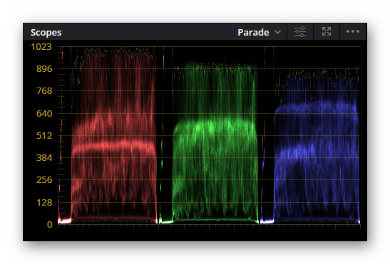
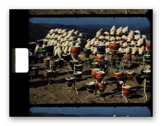
Violà, the image structure in the bright image areas is there! And the “Scopes → Parade” viewer looks like this:
grafik
The sprocket area ends up in every color channel below the maximal value (in this case: 1023) and shows structure. Because the camera’s exposure was set up this way.

This is actually not the setting I am using in my workflow. As I am not interested in the sprocket area at all, and even a clear overexposed patch of the original frame stays for sure below the sprocket values, I go again to the exposure tab, keeping an eye on the parade viewer, and raise the exposure value, in this case to -1.17. The image looks now like this:
grafik
with the parade viewer displaying the following:
grafik
Clearly, the sprocket area has been clipped with this setting. But no image area in the actual frame area is above the maximal value. Great, that’s the goal.

For this adjustment, I usually search through the whole captured footage to find a frame where there are some image areas which are burned out in the original footage for sure. I use this to set a very conservative “Exposure” value.

If you look closely at my above example you might notice that it displays the same feature as you noted above: the image were the sprocket areas are mapped into maximal white looks duller than the one were I clipped the sprocket area values. The same thing happened with your experiment. Note that in your Adobe Camera Raw example, the sprocket areas is indeed totally white, exhibiting clipping. But in your DaVinci example, the sprocket area displays structure, even a slight color cast. So what you have discovered is that the exposure value in the raw part of your development affects the overall impression of the image. And, comparing with my example, the same thing happened. Why?

Well, that has something to do with the various color spaces involved. Specifically, behind the scenes, every “.dng-viewer” program employs mapping from the linear raw values to non-linear “rec709” (or similar) values. Otherwise, your image would look really weird. Here’s the linear version of our example image:

grafik

Compare this to the image above which is actually a “rec709” version.

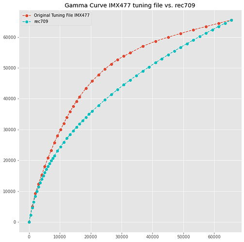
Here’s a graph of the mapping going from linear to rec709 (the turquoise curve):


Changing the positions of the raw values by playing around with the exposure value changes the apparent contrast of your image. And, while we’re at that, also the color saturation.

Summarizing this rather long post:

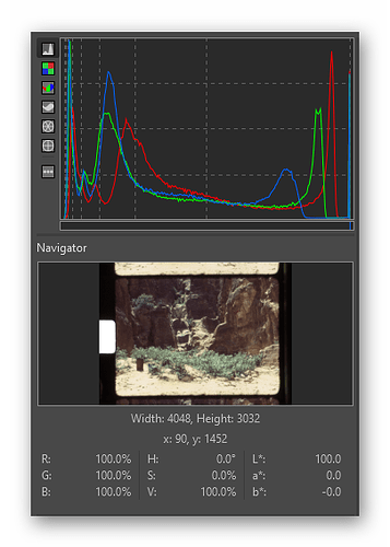
  • Select your sensor’s exposure time in such a way that the empty gate or the sprocket area are exposed to the maximal intensity value possible. This needs only to be done once and can stay forever. I use for that analysis RawTherapee, where I place the cursor in the sprocket area and I check that the RGB-values or the V-value or the L’-value are at 100% or slightly below. Note that the histogram of the raw values should not clip for the frame part of the capture. The histogram should look similar to the one below:
  • Set the exposure in the “Camera Raw” tab in such a way that you are using the maximal dynamic range but no image areas are burned out. Normally, for me, that’s it, as the the real look of the image is defined at a later processing stage. However, occationally I already push down highlights by entering a negative “Highlights” setting in the “Camera Raw” tab and a positive “Shadows” value. Another setting you might play with is the contrast setting. I have yet to discover a difference between setting these things here or later in the processing stages.
4 Likes

Here is the original image:

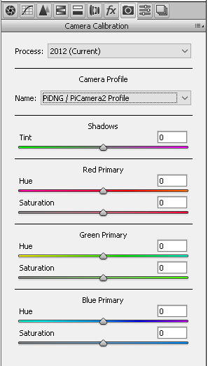
I have noticed one information in Camera Raw that might be relevant:

Apparently there is some information inside the dng file that applies a certain profile(?). It shouldn’t be the other way around (i.e. “Camera Raw detects what captured the image and applies a profile from a database”, or something), because this version of CR is from 2015.
My DaVinci Version is 18.6 by the way.

However, whatever this profile does, it is not reflected in all the other tabs of the program. All the values are at their default setting, so this profile, if it does things to the image, does this somewhere in the background (I can’t select another profile to see if things change).

How did you receive the list of dng metadata from your image?
Is your example image available for download somewhere? I’d be interested to see how Camera Raw develops it.

I’ll take another closer look at your post later in the day when I have more quiet time!

… and here you can download my raw for your experiments…

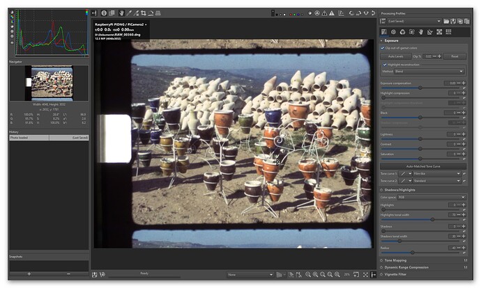
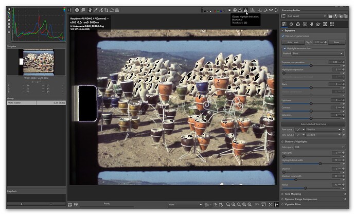
In RawTherapee, this raw image opens like so:


Note the shape of the histogram - the red channel extends all the way to the right side of the histogram. That is: it’s clipping.

RawTherapee can help you with that issue. Click on the triangle with exclamation mark in the upper right window area, and all critical areas will be marked:


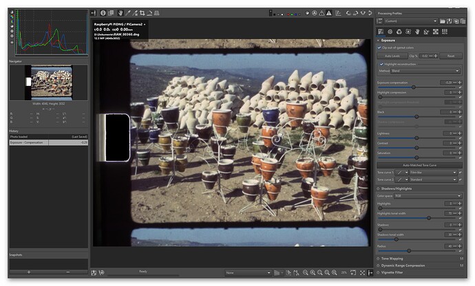
Now turn the exposure down until all black areas in the frame area are no longer marked. You should end up with something like this:

Two things to note: first, the only area still marked as “clipped” is the sprocket area, and we don’t mind this. Second, the red channel in the histogram runs out before it hits the right border. So we have found the correct exposure setting for this image.

Please note that this procedure is basically identical to the above described procedure with DaVinci - only that I did not use the histogram but the “Parade” viewer.

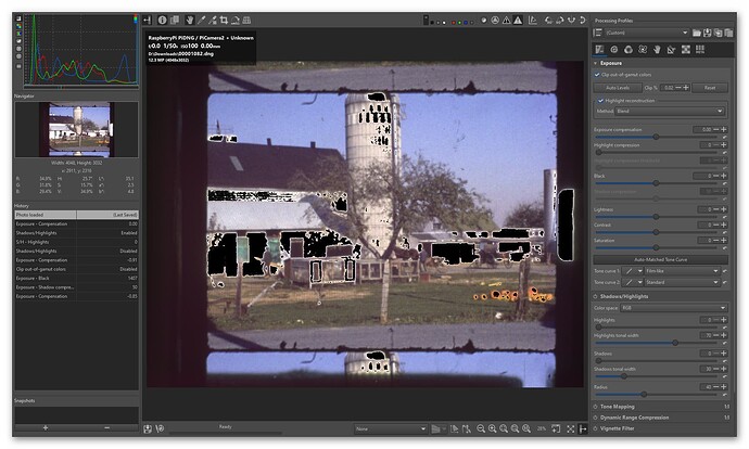
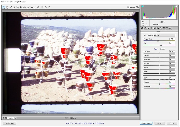
Now let’s see how this procedure would work with your raw. Here’s the initial setting, already with the clipped highlight indicator active:

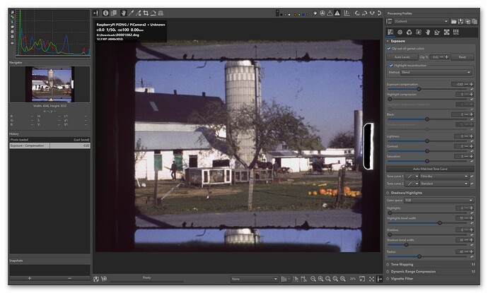
And this is how it should look like:


Only the sprocket area clips here. Good!

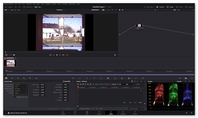
While we’re at that, the same in DaVinci. Original image loaded - way too bright, the “Scopes → Parade” viewer shows clipping.

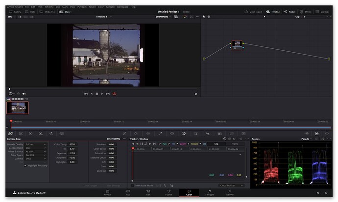
Adjusting so that all data is displayed, including the sprocket area:

Rather dark, but we set Exposure = -2.74. If you look closely, you might notice that your red channel is somewhat brighter than the blue and green channel in the empty sprocket area, but the color amplitudes of the actual frame data have about equal height - that is probably what one would aim at.

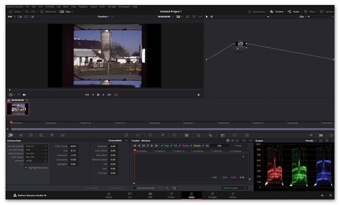
Anyway. We do not care about the sprocket area, only about the frame data. So up with the exposure again! Setting Exposure = -2.26, we arrive at this:

Note how the values of the frame data just touch the upper border of the Parade viewer. Usually, for me, I am done at that stage of processing. I only make sure that the chosen exposure works for all other frames in my capture. If you “exposure setting frame” was chosen carefully, that should be the case.

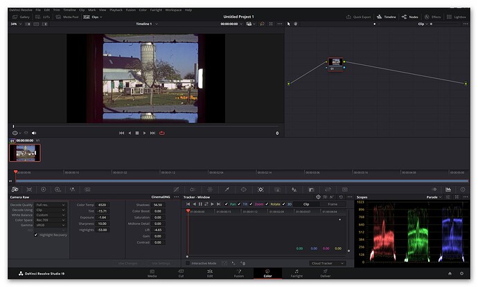
As noted, I defer al the other adjustments to a later processing stage. However, if you really want to optimize your footage further already at the level of the “Camera Raw” module, all controls are there. Here’s an example for your image:


I basically first looked at the “Shadow” setting, followed by the appropriate “Highlights” setting. Than, I readjusted “Exposure” and “Lift”. Once that was done, a little tweek on the “Tint” setting gave me a more autumn-like look of the frame. Of course, all of these setting are available also in the “Primary → Color Wheels” tab, and that’s were I usually do this stuff.

I have the suspicion that the controls of the “Camera Raw” tab work in linear space, whereas the controls in the “Color Wheels” tab work in the timeline’s color space. If so, they would not be equivalent. I still need to investigate that further.

Anyway. Here’s the data hidden in your .dng-file:

---- ExifTool ----
ExifTool Version Number         : 12.01
---- File ----
File Name                       : 00001082.dng
Directory                       : D:/Downloads
File Size                       : 24 MB
File Modification Date/Time     : 2024:10:06 11:15:26+02:00
File Access Date/Time           : 2024:10:06 12:12:19+02:00
File Creation Date/Time         : 2024:10:06 11:13:01+02:00
File Permissions                : rw-rw-rw-
File Type                       : DNG
File Type Extension             : dng
MIME Type                       : image/x-adobe-dng
Exif Byte Order                 : Little-endian (Intel, II)
---- EXIF ----
Subfile Type                    : Full-resolution image
Image Width                     : 4056
Image Height                    : 3040
Bits Per Sample                 : 16
Compression                     : Uncompressed
Photometric Interpretation      : Color Filter Array
Make                            : RaspberryPi
Camera Model Name               : PiDNG / PiCamera2
Orientation                     : Horizontal (normal)
Samples Per Pixel               : 1
Software                        : PiDNG
Tile Width                      : 4056
Tile Length                     : 3040
Tile Offsets                    : 756
Tile Byte Counts                : 24660480
CFA Repeat Pattern Dim          : 2 2
CFA Pattern 2                   : 2 1 1 0
Exposure Time                   : 1/54
Exposure Time                   : 1/50
ISO                             : 100
Exif Version                    : 0221
Shutter Speed Value             : 1/50
ISO                             : 100
DNG Version                     : 1.4.0.0
DNG Backward Version            : 1.0.0.0
Black Level Repeat Dim          : 2 2
Black Level                     : 4096 4096 4096 4096
White Level                     : 65535
Color Matrix 1                  : 0.4528 -0.0541 -0.0491 -0.4921 1.2553 0.2047 -0.149 0.2623 0.5059
Camera Calibration 1            : 1 0 0 0 1 0 0 0 1
Camera Calibration 2            : 1 0 0 0 1 0 0 0 1
As Shot Neutral                 : 0.3203177552 1 0.6680472977
Baseline Exposure               : 1
Calibration Illuminant 1        : D65
Raw Data Unique ID              : 323233303034333636303030
Profile Name                    : PiDNG / PiCamera2 Profile
Profile Embed Policy            : No Restrictions
---- XMP ----
XMP Toolkit                     : Adobe XMP Core 5.6-c011 79.156380, 2014/05/21-23:38:37
Creator Tool                    : PiDNG
Rating                          : 0
Metadata Date                   : 2024:10:04 17:24:15+02:00
Document ID                     : 6DE917EB3F26A9DCE53ED5A4CD92EBC6
Original Document ID            : 6DE917EB3F26A9DCE53ED5A4CD92EBC6
Instance ID                     : xmp.iid:af0ce410-d71d-5e40-8d00-6e4243ad0bba
Format                          : image/dng
Raw File Name                   : 00001082.dng
Version                         : 9.1.1
Process Version                 : 6.7
White Balance                   : As Shot
Auto White Version              : 134348800
Saturation                      : 0
Sharpness                       : 25
Luminance Smoothing             : 0
Color Noise Reduction           : 25
Vignette Amount                 : 0
Shadow Tint                     : 0
Red Hue                         : 0
Red Saturation                  : 0
Green Hue                       : 0
Green Saturation                : 0
Blue Hue                        : 0
Blue Saturation                 : 0
Vibrance                        : 0
Hue Adjustment Red              : 0
Hue Adjustment Orange           : 0
Hue Adjustment Yellow           : 0
Hue Adjustment Green            : 0
Hue Adjustment Aqua             : 0
Hue Adjustment Blue             : 0
Hue Adjustment Purple           : 0
Hue Adjustment Magenta          : 0
Saturation Adjustment Red       : 0
Saturation Adjustment Orange    : 0
Saturation Adjustment Yellow    : 0
Saturation Adjustment Green     : 0
Saturation Adjustment Aqua      : 0
Saturation Adjustment Blue      : 0
Saturation Adjustment Purple    : 0
Saturation Adjustment Magenta   : 0
Luminance Adjustment Red        : 0
Luminance Adjustment Orange     : 0
Luminance Adjustment Yellow     : 0
Luminance Adjustment Green      : 0
Luminance Adjustment Aqua       : 0
Luminance Adjustment Blue       : 0
Luminance Adjustment Purple     : 0
Luminance Adjustment Magenta    : 0
Split Toning Shadow Hue         : 0
Split Toning Shadow Saturation  : 0
Split Toning Highlight Hue      : 0
Split Toning Highlight Saturation: 0
Split Toning Balance            : 0
Parametric Shadows              : 0
Parametric Darks                : 0
Parametric Lights               : 0
Parametric Highlights           : 0
Parametric Shadow Split         : 25
Parametric Midtone Split        : 50
Parametric Highlight Split      : 75
Sharpen Radius                  : +1.0
Sharpen Detail                  : 25
Sharpen Edge Masking            : 0
Post Crop Vignette Amount       : 0
Grain Amount                    : 0
Color Noise Reduction Detail    : 50
Color Noise Reduction Smoothness: 50
Lens Profile Enable             : 0
Lens Manual Distortion Amount   : 0
Perspective Vertical            : 0
Perspective Horizontal          : 0
Perspective Rotate              : 0.0
Perspective Scale               : 100
Perspective Aspect              : 0
Perspective Upright             : 0
Auto Lateral CA                 : 0
Exposure 2012                   : -3.00
Contrast 2012                   : 0
Highlights 2012                 : 0
Shadows 2012                    : 0
Whites 2012                     : 0
Blacks 2012                     : 0
Clarity 2012                    : 0
Defringe Purple Amount          : 0
Defringe Purple Hue Lo          : 30
Defringe Purple Hue Hi          : 70
Defringe Green Amount           : 0
Defringe Green Hue Lo           : 40
Defringe Green Hue Hi           : 60
Dehaze                          : 0
Tone Map Strength               : 0
Convert To Grayscale            : False
Tone Curve Name                 : Medium Contrast
Tone Curve Name 2012            : Linear
Camera Profile                  : PiDNG / PiCamera2 Profile
Camera Profile Digest           : 57D05906E51D353BBF302E5EE4A0CC2E
Lens Profile Setup              : LensDefaults
Has Settings                    : True
Has Crop                        : False
Already Applied                 : False
Photographic Sensitivity        : 100
History Action                  : saved
History Instance ID             : xmp.iid:af0ce410-d71d-5e40-8d00-6e4243ad0bba
History When                    : 2024:10:04 17:24:15+02:00
History Software Agent          : Adobe Photoshop Camera Raw 9.1.1 (Windows)
History Changed                 : /metadata
Tone Curve                      : 0, 0, 32, 22, 64, 56, 128, 128, 192, 196, 255, 255
Tone Curve Red                  : 0, 0, 255, 255
Tone Curve Green                : 0, 0, 255, 255
Tone Curve Blue                 : 0, 0, 255, 255
Tone Curve PV2012               : 0, 0, 255, 255
Tone Curve PV2012 Red           : 0, 0, 255, 255
Tone Curve PV2012 Green         : 0, 0, 255, 255
Tone Curve PV2012 Blue          : 0, 0, 255, 255
---- Composite ----
CFA Pattern                     : [Blue,Green][Green,Red]
Image Size                      : 4056x3040
Megapixels                      : 12.3
Shutter Speed                   : 1/50

To obtain that data, simply use the tool noted at the first line of this file “ExifTool”. It works since a .dng-file is basically at heart a simple .tif-file - just with a few extra tags.There are online-tools for that available (search: “exiftool online”), if you do not want to set up this nice program on your computer.

Some final thoughts. What your Camera Raw is indicating is that it is using the profile information embedded in your .dng-file. You could opt to use a different profile, but I would not recommend that in our case.

The “profile” consists of quite some data (see the above listing), but not all of that data is actually used. We already discussed the tags Black Level and White Level which are the first parameters used in “developing” your raw data. Once these have been applied, color information is used to convert the raw data into a decent color space (say, sRGB or so). There are a lot of tags coming here into play, depending on the type of .dng-file. In our case, a .dng-file created by picamera2, we are working with the most simple type one can imaging. Only the As Shot Neutral tag and the Color Matrix 1 tag need to be used. Other tags in the picamera2-dng are nonsense, like the Calibration Illuminant 1, normal dngs feature actually at least two Color Matrix and Calibration Illuminants - this is a wild west area with a lot of uncertainties. So whether your raw developer does inpret the information in a picamera2-dng in the correct way or not is not clear. Judging from my tests, at least DaVinci, RawTherapee and Darktable do it right - no idea how Adobe’s stuff performs here.

EDIT: I noticed that the tags of your .dng-file look different from my raw files.

For example, in your file it’s Tile Offsets : 756 but in my (recently captured) file, it’s Tile Offsets : 760. Also, your .dng has two Exposure Time tags (?) and a Shutter Speed Value tag which is missing in mine. Lastly, there is a XMP Toolkit tag-section with a lot of auxilary data which indicates that you ran the original raw file through some converter? Or at least your Adobe Camera Raw sets some additional tags in your original .dng-file without telling you. In any case, the file you linked above is not the original file as created by picamera2. Whether this has an influence on how for example DaVinci interprets your raw data I do not know - default behaviour would be to ignore these tags, but you never know…
2 Likes

Thanks for taking the time.

The raw file I shared is straight from the HQ camera. But the first thing I did was open it with Camera Raw. It does seem to leave a few marks…

XMP Toolkit : Adobe XMP Core 5.6-c011 79.156380, 2014/05/21-23:38:37

You can choose to embed the xmp data into the original raw image, which is my default setting (as opposed to having separate xmp files lying around). So that’s probably it. And that might also be the reason why you only had to barely adjust exposure in RawTherapee.
I’m using a Pi5 by the way. But you probably already deducted that from the metadata.

When I open your file in Camera Raw, default settings look like this - overexposed with some clipping. Good to know.

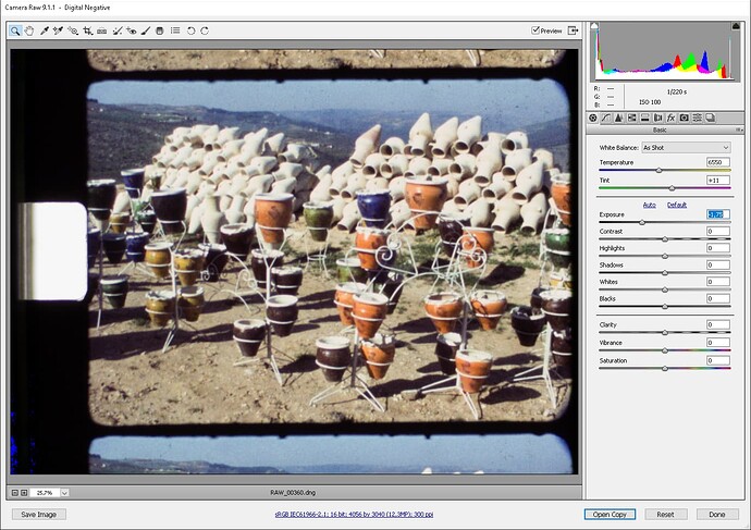
After taking down exposure, I get this:

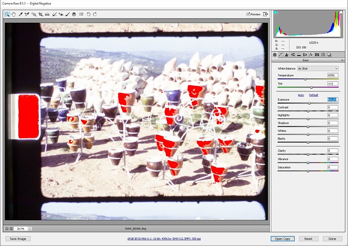
Interestingly the sprocket hole isn’t marked as clipping at all. I need to up exposure by about 0.20 for it to start clipping. Then things look like this.

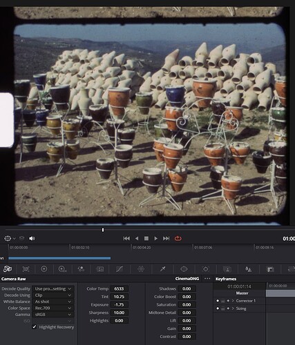
In DaVinci, with the same adjustment (exposure -1.75), it gives me this:

And after some dialing I think I’ve found the main difference between both programs: Adobe applies more contrast, even though the number is 0 both times.

The result still isn’t identical, but it’s clear to me now that nothing has gone “missing”, or something. The Adobe development looks more appealing at first glance, but the dark areas initially seem to have more detail in DaVinci (at least on my monitor which supposedly covers 99% of sRGB and 70% of AdobeRGB color space but unfortunately isn’t yet wide gamut).

Well. I feel like I was a bit hasty with my initial question, but it’s still interesting to see how different programs seem to have different ranges/defaults for their dials.

1 Like

Well, I have to say that now (sorry): in my view, “the Adobe development looks more appalling at first glance” - and even if you look deeper.

While Adobe did something right with the invention of the manufacture-independent .dng-format, it’s software and commercial offerings are not comparable to other vendors, say Blackmagic Design, for example. As you might have noticed, I never use Adobe software if I can avoid it.

Having that said, a few other comments. A dial setting in one program might have nothing to do with the same labeled dial setting in another program. Even if they are basically the same, the way the setting is applied to your image (the algorithm) might be quite different.

Also, what you see on your display is not the real data. It’s subjected to some intensity remapping - simply because the developed raw data is linear and would look aweful when displayed directly (I included an example in a post above).

Ok. As you remarked, your monitor can display 99% of sRGB - and that’s about currently the standard. Now any color space one is working with has two major settings: the position of the primaries and the contrast- or gamma-curve applied to the pixel values. For HDTV material, the correct contrast curve should be rec709 at this point in time - at least I think so. However, camera manufacturers as well as software designers tend to beautify their data (images) a little bit, deviating from that spec. Clearly, in your Adobe software, something like this is happening. (note that the “99% sRGB” concerns only the location of the primaries and has nothing to do with the contrast curve).

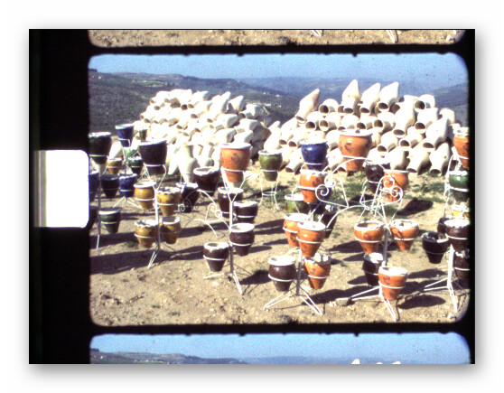
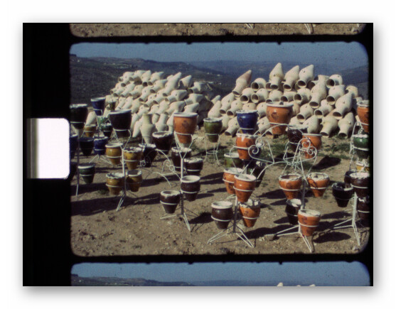
Have a look at the contrast curve graph a few posts above, where two different contrast curves are displayed. One comes from the standard tuning file of the HQ camera, the other is striktly rec709. Now compare this image (standard tuning file)

with this image (scientific tuning file):

The difference is noticable and is in mainly due to the different contrast curves used.

For the casual observer, the standard tuning file looks probably better - better contrast, more color saturation, great! But I can assure you that the scientific tuning file result is closer to the actual scene colors. Again, the major difference is the contrast curve applied. And something like this is most probably what is happening with your Adobe software - some unspecified, “extra tuned” contrast curve is applied before actually displaying your image on your screen.

Well, there is a reason DaVinci has quite a few setup parameters for proper color management. That’s not an easy business. In my personal setup, I use two identical displays, one is operating as pure sRGB display, one is set up as rec709 display. Only the later is used for color grading. In this way, I try to at least assure that the final video confirms to the spec. In the end, every display unit (mobile phone/PC/TV-set) will apply again some “beautifying” image processing anyway and screw the colors (as well as other things) again. But well, …

1 Like

Again, I’d like to assert that this advice is almost a decade out of date.

The best selling OLED TV at Best Buy’s website is listed as 99% DCI-P3.

Glance at the first page of PC monitors for sale at any site and you’ll see marketing text like “95% DCI-P3 125.7% sRGB” right in the product title. There’s even a “99.3% DCI-P3 / 139.1% sRGB” just two products above that one. They’ve started including AdobeRGB(!) numbers in the marketing text because of how wide these gamuts are getting.

Sure, those monitors are on the higher-end of the consumer monitor lineup. I don’t know how many of those are making their way to users. But here’s an easier to find statistic: Apple has been selling ~250 million wider-than-sRGB gamut screens, every year for years now. Here’s a WWDC presentation from 2017 (which still sounds recent to my ear but is already 7 years ago :sweat_smile: ) where they end the talk by saying “… and lots of your users already have compatible [with Display P3] devices in their hands today”.

9(!) years ago Android devices were already being shipped with a “limit colors to only sRGB” mode to rein in their gamuts because the screens could already show more than sRGB. (Android’s color management was kind of a mess back then and lots of sRGB content was being scaled incorrectly to the wider gamut, so users were voluntarily using the narrower sRGB gamut until Android got their color management act together.)

All of that is to say these screens are out there. A lot of them. For a long time. Across a wide swath of consumer demographics.

Mastering for sRGB today seems short-sighted. Some of this old film stock (I’m looking at you, Kodachrome) has these lovely, wonderful, vibrant colors. Squashing them down to sRGB or Rec.709 feels like such a waste when a substantial portion of regular, everyday display devices already have access to wider colors.

2 Likes

Haha, no problem. Scrolling through my post on my phone also made me prefer the DaVinci version.

This might be a super-dumb question, but: Can I master for a bigger color space without a proper display? Mine is 10-bit at least, and I can see a slight difference when switching Camera Raw to AdobeRGB, but that’s about it. What is the Pi HQ camera’s native color space anyway - if there is such a thing?
…I think my knowledge is a bit too limited to ask the right questions.
At some point years ago I started working with raw/cr2 files for photgraphy and remember getting “washed out” colors after working in AdobeRGB and then saving as sRGB for web. Since then I’ve just switched to always working in sRGB color space, and never truly thought about color profiles and such again…
What’s the best/right way to preserve the colors the camera saw during DaVinci’s workflow?

(I don’t mind getting pointed at the odd Youtube video, if this is too much of a rabbit hole…).

Well, sure. But a quick Google search yielded that youtube recommends bt.709 (which is rec709 in disguise) for normal content, and rec 2020 for HDR content. I confess that I have not yet done my homework here, but what is a display with a wide gamut good for if delivery channels and/or player software do not support it? Again, I have not yet looked to much into this aspect. Grading in rec 2020 is much easier than in rec709. So I am happy to learn more! :+1:

I guess I don’t have a definitive answer, but it seems like if you can’t see the colors while editing, how could you know what they were going to look like on the target device? So my guess is a “no” here. (Presumably this is why the pro/studio editing monitors are like an order of magnitude more expensive than consumer gear.) :grimacing:

For all my bluster above, this is one of those unfortunate things that still happens a little too often for my tastes. The “washed out” thing can happen with only a single weak link in the chain. I was just doing some color grading tests on some TIFF stills a few days ago when I discovered that (still, in 2024) neither Windows 11’s own image viewer nor the 3rd party viewer I prefer (“nomacs”) supported color management at all.

So even though the editor can do it and the file format can store it… the viewer(s) right at the end of the chain got it wrong and now the colors were different than my expectation.

This dovetails into:

I agree the problem hasn’t been completely solved. I’m generally indifferent to Apple’s products, but this is one place where their ability to control the whole vertical from hardware to OS to software (paired with making good color management a priority) has done a nice job. It feels like you bump into the “washed out” (or the inverse “over saturated”) problem less often on that side of the fence than you do in Windows.

That said, I think the better and more universal answer to the player software question is “the browser”. I wish YouTube were a little more permissive about their recommended gamuts. I don’t want to go all the way to an HDR workflow, so having something between here and there would be nice. But the raw browser (which is really just another way of saying “Chrome”) seems to have good color management support in the built-in video player. Between Chrome and WebKit, you end up with ubiquitous color support on all platforms. Point them at an .mp4 file directly and (as long as it’s encoded in the file correctly), the color should be right.

The Wide Gamut Test Page is a good demo for this. My wide-gamut-but-not-HDR PC monitor shows all the non-HDR results correctly. (I can see the “W” in the red square, etc.) And my iPad Pro shows everything correctly.

The trick is avoiding 3rd-party sites that re-encode your files and muck with the color information. YouTube always reencodes everything, so it’s probably not the best place for files you’re being very particular about. I’ve never tested whether Vimeo mucks with the color information, but simply dropping your file someplace like S3 (where the storage costs round to zero cents) and pointing a browser at the video’s URL should be something anyone can do on any device and see it the way you intended.

So that’s the delivery target I’ve had in mind: just some web page I make that points directly at these video files. That way my whole family should be able to see them as-intended on just about any device they have.

2 Likes

Well, my trusted old Samsung S20 fails miserably - as did a bunch of random Win-PCs I tested:

So… - at this point in time, it’s probably safe to call rec709 a standard. Assuming availability of higher color gamuts and HDR capabilities is probably geared more towards the “bleeding edge” variety in my opinion.

We have the situation that:

  • S8 film stock certainly exceeds the rec709 gamut
  • S8 film stock should be mastered in HDR, due to it’s large dynamic range.
  • the HQ sensor has a larger color gamut than rec709 - but: it is not yet known to me how large that gamut is.
  • the HQ sensor barely has the dynamic range necessary for S8 footage (so do other cameras)
  • DaVinci is happy to work in larger color spaces, all a question of proper setup.
  • Transport layers and final displays are at this point in time not guaranteed to deliver wider color gamuts. But they will, at one point in time.

So well… - I think how to solve this depends on a lot of personal choices, including available hardware. I do not own a color-calibrated HDR monitor, so successful grading of wide color gamut HDR material is out of my scope. My targets are friends and family, which for sure have rec709 or sRGB hardware. And probably no idea how to set things up on their Win-PC or mobile for higher quality display. My source (the HQ camera sensor) does not really yield sufficient data to entertain wide color gamut/HDR encoding. Youtube converts your wide color gamut footage to rec709 anyway. So at this point in time that’s my choice. That might change in a year or so, but then I might discover that the old HQ-based scans are of lower quality than what I really want to use. I don’t think there is a good answer here, and certainly not a universal one.

1 Like