@cpixip if you have an interest in reverse engineering that unit and its software, I’d be happy to support that effort.
… well, Frank Vine’s color control system is quite powerful. It switches the LEDs on during a short time when the camera takes the frame. Otherwise, the LEDs are off. So it’s a pulsed system, and as Frank remarks, “not suitable for use with rolling shutter cameras.” The Raspi HQCam is a rolling shutter camera, among others.
With a help of a FET, a microprocessor can switch on-off any LED quite precise. That is what is used in Frank’s system for exposure control. He even describes the electronics used at his page.
The system monitors the temperature of the LEDs and applies a temperature correction. I have my doubts that something like this will have noticable effects in this setup, as the switching of the LEDs leads to a continous temparature change during operation. Maybe it’s operating on a time-averaged setting.
The special twist of this system is that the image from the camera is analyzed and the LEDs are driven in such a way that the maximum dynamical range of the camera is used in every color channel. In this way quantization effects and noise are reduced. Of course, the frames captured will have a weird color balance which needs to be corrected in the post.
Well, if you design a system from scratch, you have many options available. Here’s my take on a illumination system:
-
Will your film be running continously and you need to freeze the frame by flashing? If so, you will need a global shutter camera and a LED system which you can trigger fast and reliably. Simpler and cheaper is to use rolling shutter cameras and a continously operating illumination system. For this to work, you obviously need to stop the film during frame capturing.
-
Do you want to scan film material which is severly under-exposed or even off-color (maybe forgot to switch on the daylight-filter, for example). If so, you will need an adjustable light source with a sufficient power reserve. On the other hand, a lot of people have obtained resonable results with a simple white-light LED, compensating with the camera’s whitebalance and exposure settings. Of course, in doing so, you will not be able to use the full dynamic range of your camera.
-
Depending on the film material, your camera might not have the power to resolve the full dynamic range of the film. To optimize here, you have two options: one, as noted above, is to use your cameras whitebalance and exposure settings. The other is to employ an adjustable light source to maximize results, while keeping the camera settings to fixed values. The later option has the advantage that LED-light sources can be switched usually much faster than usual cameras. You can basically vary the current of the LED (not much used), or the duration the LED is switched “on” (PWM - defacto-standard nowadays, big advantage in heat dissipation, among other things). If using PWM, you need to make sure that the switching is done with a high enough frequency in order not to run into beat patterns or flicker problems.
-
Film material which is/was used for projection is tuned to the spectrum of bulbs, which is very different from the spectrum a LED light source produces. Actually, there’s even a difference spectrum-wise between a light source composed of red, green and blue LEDs and a “normal” white-light LED. In any case, there is also the spectral filter characteristic of your film, which will vary between different film stock, and the spectral sensitivity of your camera. All these spectral characteristics interact and make it kind of difficult to arrive at an optimizal light source. And an optimal LED combination for Kodachrome might not be perfect for Agfachrome or Fuji stock. It’s probably easier to tune all that in post production.
-
What you can optimize is the dynamic range your camera is operating on. Here’s my take on this: all film stock I have encountered (Super-8 home movies) have occationally some part of the frame which is so heavily overexposed that it is pure white, i.e., the pure light from the illumination source is shining through. Clearly, this gives you the upper range of intensities you not want to be clipped by your camera. Now, consumer-grade cameras (including the Raspi HQCam) are somewhat optimized for daylight operations. “Daylight” corresponds to certain white balance settings of the camera, and it is that setting one should use in manual whitebalance mode. If you do so, these clear patches in your film material probably won’t be really white (actually, you have to check this with an exposure setting low enough so that these light patches turn grey, in order to stay away from clipping effects). If you now tune your light source so that these patches appear grey again, you are going to have nearly equal amplitudes in the red, green and blue color channels of your camera. Not perfect, but close enough in my experience.
-
Film will have scratches. Some are minor and can be handled by appropriate light source design. Basically, you want to shine light through the film frame from every angle possible. There’s only one design which does that perfectly, and that is an integrating sphere. However, for this to work as intended, you need to place the film as close as possible to the port hole of the sphere. Any further distance reduces the incident angle of the illumination, reducing in turn the desired effect.
Well Matthew, I probably would not really know what to reverse-engineer…
The basic operation of the unit is quite well described at Frank’s webpage, even the circuit diagram he’s using is there. From what I understand the system is basically a hardware-based unit with dials for adjusting the red, green, blue and an additional “IR”-channel.
The temperature-compensation Frank is mentioning is quite interesting, but highly probable tied to the specific LEDs he’s using. Since he’s driving all LEDs of a channel in series, variations of the LEDs respondance to a certain current (which happens with real LEDs) would not be covered by such a temperature compensation. Also, at least in my experience, temperature drift of LEDs has barely a noticable effect in real captures (given, I have done only a few experiments about this and never looked back - maybe I should revisit that theme again…)
Well, continueing: presumably one additional microprocessor in Frank’s unit is acting as a kind of sequencer, receiving a trigger input itself and than triggering in turn the different LEDs and the camera, for example to realize separate red, green and blue captures of a given frame with a monochrome camera. He’s using PICs for that, I would certainly use some Arduino-clone nowadays.
The hardware unit features for every channel a simple constant current source, plus a simple FET-switch for the realizing the pulse timing. The LED current seems not to be adjustable - for a redesign, that would be certainly an option to consider adding. If so, you could use the unit in both ways, either in varying current mode, or in varying exposure time mode. Or even in a combination…
The software he’s describing seems to be actually split in two parts - one software is a capture software for firewire-cameras. Nice, but, in sense, firewire probably had it’s days. New interfaces (USB3, CameraLink, GigE and CSI) offer much higher transfer rates and in turn potentially higher scan resolutions.
The other piece of software he’s decribing is a application which is just a software recreation of the real dial hardware, enabling you to turn the knob on your screen without turning to the real hardware. The only thing I can imagine important here is that watching the real-time histogram (of his capture software) with selectable region-of-interest can be combined with the on-screen dials to optimize the light source for a given scan (for using the full dynamic range in all color channels, for example).
4 Likes
Regarding 3: Isn’t this exactly where a machine vision camera shines? Changing exposure and whitebalance settings on the fly that is. Currently looking through the SDK of a machine vision camera to check if there is anything about this in there.
well, that should be the idea. What is happening when you request an exposure change might depend on the camera model. I would be actually interested in getting some data for different camera models.
I started with Raspberry Pi cameras, and they all feature a lot of automatic things you can not turn off, interfering with exact exposures. I tested one camera which is used in machine vision applications, the
and was surprised that at least this camera features the same problem as the Raspberry Pi’s cameras.
Specifically, I did the following experiments. A fixed frame was imaged continously by the camera. At a certain time point, a new exposure was requested. The average intensity of the image should ideally jump right to new value, corresponding to the exposure requested and stay there.
Of course, caused by the images already recorded but not yet consumed by the image software, one expects a certain delay between the exposure trigger and the change in average intensity. Ideally, it would be just a single frame.
Now, here’s a diagram of what happened:
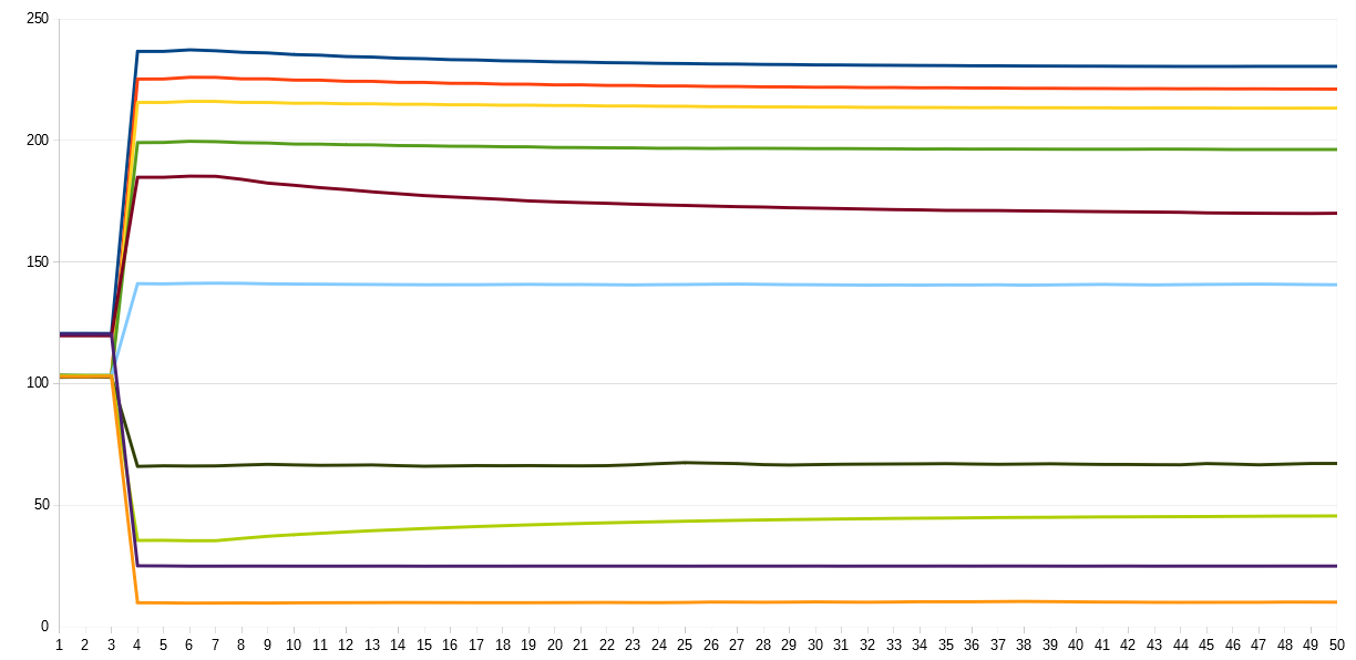
The x-axis shows the frame numbers after a new exposure was triggered, the y-axis the average intensity of the frames. Clearly, it takes 3 frames until the camera reacts to the new exposure. These 3 frames are presumably just the intrinsic pipeline delay.
The inital new intensities the camera delivers after the third frame are actually not correct - the intensities the camera delivers 50 frames after the new exposure are more appropriate for the exposure requested. Note how long some exposure changes took and how uneven the response was, depending on the difference between initial exposure and new exposure requested.
I am sure that there are cameras which perform better in such a test, but I have none available. Most manufacturers do not bother to give any hint on the processing pipeline delay (here: 3 frames) or on the speed of exposure changes.
Another twist: normally, the exposure time you are requesting is mapped to certain camera registers. And these registers usually have some constraints. So it might happen that you request an exposure time of 1/1000 sec, but the camera will actually use 1/1024 sec instead. By the way, this happens occationally with normal DLSRs as well. Nothing to worry about normally, but if you depend on precise exposure times, something to be aware of.
So, anyway. For me (and probably anybody wanting to go into HDR/exposure fusion) it would be very interesting to get some information on the performance of other under rapid exposure changes.
1 Like
@cpixip what do you think about the relative merits of Frank’s ‘squeeze maximum dynamic range from the CCD’ and correct in post approach, versus exposure fusion, for getting the maximum out?
Having seen how much dynamic range is in reversal film, and how a CCD camera struggles to get anywhere close when averaging out, I have to be honest I am a bit sceptical as to whether it is worth investing focus in each RGB part of the spectrum being maximised. If you are still missing dynamic range and want to do exposure fusion on top, you would need to build a very complicated system that does both. The reaction times you mention above surely must be an issue with most cameras, as the FLIR camera I’ve got really does not react fast enough to do spot on exposure from one frame to the next at any reasonable transfer speed (I would call 3fps ‘efficient’ for a DIY system).
Trying to wrap my head around how to do frame by frame CCD optimised PWM, with multiple exposures stitched together… probably simple once built? But very intimidating and perhaps unlikely to give much benefit above going straight for exposure fusion? ¯_(ツ)_/¯
1 Like
@bainzy - well, one point in Frank’s approach is to utilize the maximum dynamic range of each color channel during capture. Given the dynamic range a typical color-reversal film is able to display, this is probably a sensible approach.
For cinema type of movies, you probably can set the illumination levels for a choosen reference frame and digitize the whole film with these settings. This is different with the material I am mostly concerned with, Super-8 home movies. Here, there will be over- and, more often, under-exposed scenes interwoven with normally exposed ones. In this case, you will need to readjust illumination intensities on the fly, preferably by some feedback system analyzing the capture in real-time.
Now, in any case, each raw scan will initially not be properly white-balanced; you will need to correct that during post-production. If you are planning to color-grade the final movie anyway, that is probably not a big deal.
In contrast, I wanted a mostly automated system which can tolerate some exposure variation and which would avoid the processing of 14-bit or more raw camera data (with my cameras, I can get anyway only 12-bit raw data). After a lot of experiments, I finally settled for employing exposure fusion, based on 5 images taken ranging over 5 EVs.
What is the difference compared to capture a single raw frame with properly adjusted illumination levels? Up to this point in time, I can still not give a definite answer, because I simply did not have the time to make some additional experiments. Anyway, what I know so far:
-
A well-exposed single raw camera capture with 12 or 14 bit resolution can capture basically the full dynamical range of a color-reversal film. It is much faster than taking the 5 or so needed, different exposures for exposure fusion. If you go for exposure fusion and take 5 exposures by varying quickly the illumination source, you can work much faster than if you keep the illumination constant and vary the exposure time of your camera. Still, exposure fusion is much slower than a single raw capture. I am currenty able to scan 1 minute of 18fps-film in about 34 minutes.
-
12 to 14 bit is barely enough to capture the full dynamical range of color-reversal film. Slight variations in the exposure of the original film might push your working envelope in such a way that either the shadows are being just pure black or the highlights being burned-out. Whether this is noticable in the final scan remains to be seen - after all, your end product will normally be displayed anyway on a limited 8-bit display.
-
With illumination-optimized raw captures, your original material will be off quite a bit from what you want to achieve for final presentation - thus, extensive (manual) post processing is needed. With exposure fusion, color corrections needed in post production are less severe. Exposure fusion has the tendency of averaging out certain variation - so post production work is reduced. You can see some examples of this “averaging out” of original film variation in the examples I posted here.
-
Exposure Fusion is a computationally expensive algorithm, and it scales badly with scan resolution. I never tried 4K, but with 2012 x 1512 px, I need with my not-so-bad desktop 2.3 seconds to combine a single frame into the output frame. This adds substantially to the overall time you have to invest for scanning a given amount of film. Processing of 1 min of 18 fps film will take about 41 min. That is longer than the actual scanning time! Since this is an automatic process, I usually let the stuff run overnight. In total, my system currently needs at a resolution of 2012 x 1512 px for 1 min of 18fps film a processing time to arrive at the exposure fused base material of 1 hour and 15 mins. Nothing for the impatient!
-
Because a lot of computations are involved, the output image of the exposure fusion algorithm is a little bit less sharp than the image one would obtain from a single raw capture. That can however be corrected by an appropriate sharping step during processing. Furthermore, exposure fusion has the tendency to enhance sligthly local contrast features - this improves overall image perception a little bit. You can see this if you look closely at the original size images I posted above and compare.
-
Exposure fusion does not benefit at all from a finely tuned illumination. That is caused by the huge range of EVs covered. Given, each EV exposure is only output (as a jpg) with 8 bits (per pixel, per color channel), but the number of digits available in the 5 different exposures covers a wider dynamic range, probably equivalent to a raw capture with more than 18 bits (I need to calculate that in more detail - this is just a back-of-the-envelope estimate). You can see this in the examples given here as well. The second and third example given there would have needed very different illumination settings if done with a single raw capture (the second example is very bright, the third example very dark). Exposure fusion just picks the right illumination level automatically. As a matter of fact, the illumination/exposure levels in my approach are set to the maximum intensity of the light source, not at all to what specific film is actually scanned. The values stay fixed whatever I scan.
2 Likes
** don007**
Great job! What camera did you use?
Watched the Trailer. It is fantastic. I think the noise you see is Film Grain. No fault of the Camera. What is the Camera you used?
What kind of optics and light did you use? Show a photo of your installation!
I have sent him a mail regarding the camera and got a reply. The camera
IDS. Model UI-3080CP-C-HQ_Rev_2.
https://en.ids-imaging.com/store/ui-3080cp-rev-2.html
It is from a South Korean company
DS Imaging Development Systems Korea
Poonglim Iwant Office A-dong Room 607
170, Seohyeon-ro, Bundang-gu, Seongnam-si,
Gyeonggi-do 13590 South Korea
I assumed that he was photographing a projector gate at 24 fps. I asked him about that and did not get a reply.
well, “ids” is actually a German industrial camera manufacturer, established 1997. The South Korean branch of ids was - as far as I know - opened in 2015. The specific model “UI-3080CP-C-HQ_Rev_2” features a resolution of 2456x2054 px (global shutter) with a 12bit DAC. Pixel size is 3.45 microns. The unit has an internal image memory of 128 MB and can sustain frame rates of up to 77 fps (triggered). Connector is USB 3.0 plus an additional connector featuring flash output/trigger input. So in total, that’s not a too bad camera for the purpose.
1 Like
Thanks for the update.
So in total, that’s not a too bad camera for the purpose.
But a bad camera? could you please elaborate?
Hi @Udayarangi - well, not absolutely sure what you are exactly aiming at with your question. My “not a too bad” camera comment was referring to a “decent” camera for that purpose. Clearly, as it is an industrial camera, it is rather pricey (at least for my budget). The resolution is ok for Super-8 and similar formats, but kind of low for 16mm or above (at least for archival purposes). The 12 bit DAC is nowadays average. You can get cameras with 14 bits which will give you more head room with under- or overexposed material. The USB 3 interface is fine, but not really well supported with various hardware/software combinations (WIN10/Linux + opencv comes to my mind, for example). Being able to trigger the camera with up to 77 fps is great. But all of these characteristics are taken from the manufacturers data sheet and you only find out what the camera is really delivering in your hardware/software environment once you have bought and started the camera in your setting. From my experience, you are always up to some surprises at that point…
However, if your question refers to some examples I would not use in digitizing film, here’s a short list:
-
photographic cameras - while those cameras without doubt deliver nice images and great raw material, they tend to be endlessly slow in photo mode. Operating them in video mode is a different beast. Some older cameras did have heat issues when being operated over extended times in video mode, but that might not be an issue anymore. The “nice” keyword above hints at another issue which is often overlooked - these cameras tend to employ a lot of tricks to make the image viewable, and you might not be interested in such things in an archival setting. There is rumor around the web that even in “raw” mode, some image processing (noise-reduction) is already taking place at the sensor level for certain cameras.
-
the Raspberry Pi cameras V1/V2 - I include these here in my “no use”-list because a lot of film scanner projects (including my own) tried to use these. One of their advantages is the fast camera interface (and the price, of course). But the sensor chips of these cameras stem from mobile phone applications, tuned to work with a tiny lens with short focal length. In a film scanner environment, you will need to exchange the standard lens with a lens of much longer focal length - and this does not match well with the micro-lens array in front of the sensor chip. What you end up with is a dramatical increase in color channel mixing from the center to edges of the frame. And this color mixing leading to desaturation of colors on the edges is unrecoverable. Note that the new Raspberrry HQ camera does not have this issue.
So, in total, what constitutes a “good” or a “bad” camera depends heavily on the setting in which the camera is being used. Also, the boundaries of what sensor is good for a certain task tends to blur in recent times, as methods of computational photography nowadays are able to create sufficiently good material even from rather inferior sensor chips.
4 Likes
@VitalSparks sent these links to me and I’d thought I’d share. Some more info on lighting and color:
This is an great video on the subject of integrating spheres that came out a few days ago.

As part of the video a couple of papers are reviewed.
This one on the subject of 3D printing an integrating sphere.
This one on the subject of the paint for the sphere surface.
Thought it was a good reference to hang on this great thread about lighting.
1 Like
I too was looking for an easy way to do an integrating sphere.
Just 3D printing with PLA or ABS maybe won’t get you the surface finish you’d like without a lot of sanding, and then you’d have to worry about how much light is going to be dispersed and absorbed in the plastic.
If you’re going to use Barium Sulfate for the highly reflective coating, then it may not matter much what material you use. Instead of trying to design and print a 3D model, I found these cheap alternatives on Amazon:
55mm ping pong balls $1 each
40mm ping pong balls $0.58 each
25mm stainless steel spheres $4.50 each
The Barium Sulfate is trickier to find. There’s only a couple dodgy “extra pure” listings on Amazon, and on eBay the good stuff (97%) seems to come from the UK with shipping costs 4X the purchase price.
Another alternative may be paint. In the home theater groups that look for a good flat, white it seems the Glidden Diamond Pure White Matte paint is recommended. Available at Home Depot for $28/gal and maybe $7 for a sample size. Could probably be mixed with Barium Sulfate for even higher reflectance.
For the ping pong balls, I was even considering getting lazier and not even coating them with Barium Sulfate, but crumpling some aluminum foil to get it good and crinkly (for random reflection) and then wrapping that around the outside of the ball to eliminate any light loss through the walls.
Again, these all fit my “good enough for great results” mantra and probably not archival methods.
I’ve got a spreadsheet that will calculate the size of integrating sphere you need for a given film size (8, 16, 35) and the number and size of LED’s you’re using. I need to clean it up for general consumption and post it here…
Fun stuff!
Update on some places to get Barium Sulfate:
Etsy 1lb, 99.0%, $18
Carolina Biological, “Lab Grade”?, 500g, $19
DotMed, expired enema kits!, 96%, $18
Amazon, 1lb, ??%, $23
2 Likes
I used the 55mm ball without any coating.
There is a small injection defect on the “poles” of the ball that is visible from the insight only, so when opening the hole orient the ball so it is opposite to the nice flat area.
The last part of this post shows some variations of the light.
And all the measurements of the LED drivers in this post are also using the 55mm ball.
I would recommend blocking the back to avoid external light to blend with the surface of the ball.
Was also considering experimenting with painting the inside of one, but put it aside for now.
Is it good enough… yes, very much so. No 3D printer here, so I try to use what is available.
I’ve got a spreadsheet that will calculate the size of integrating sphere you need for a given film size
Looking forward to that!
In my experience, although there are off-the-shelf options for making spheres, mounting them to other components can get tricky. That’s why I went with 3D-printing + barium sulphate.
@PM490 Thanks for those links. That paper on paint mixing is the one I used for Kinograph’s sphere. Recommended!
1 Like