SnailScanToo or 2

Spring Sprint: Image/Color Processing and File Output

It is appropriate to clarify what Tingopix is doing regarding image processing and file output. The project uses the picamera2 library in an unconventional way to achieve a few specific goals:

  • Direct back-to-back capture of RAW data and real-time image processing of the bayered RAW for sprocket hole detection and image monitoring/waveform.
  • Maintaining and averaging for maximum bit depth from capture to file.
  • Finding the best possible quality-to-speed trade-off.
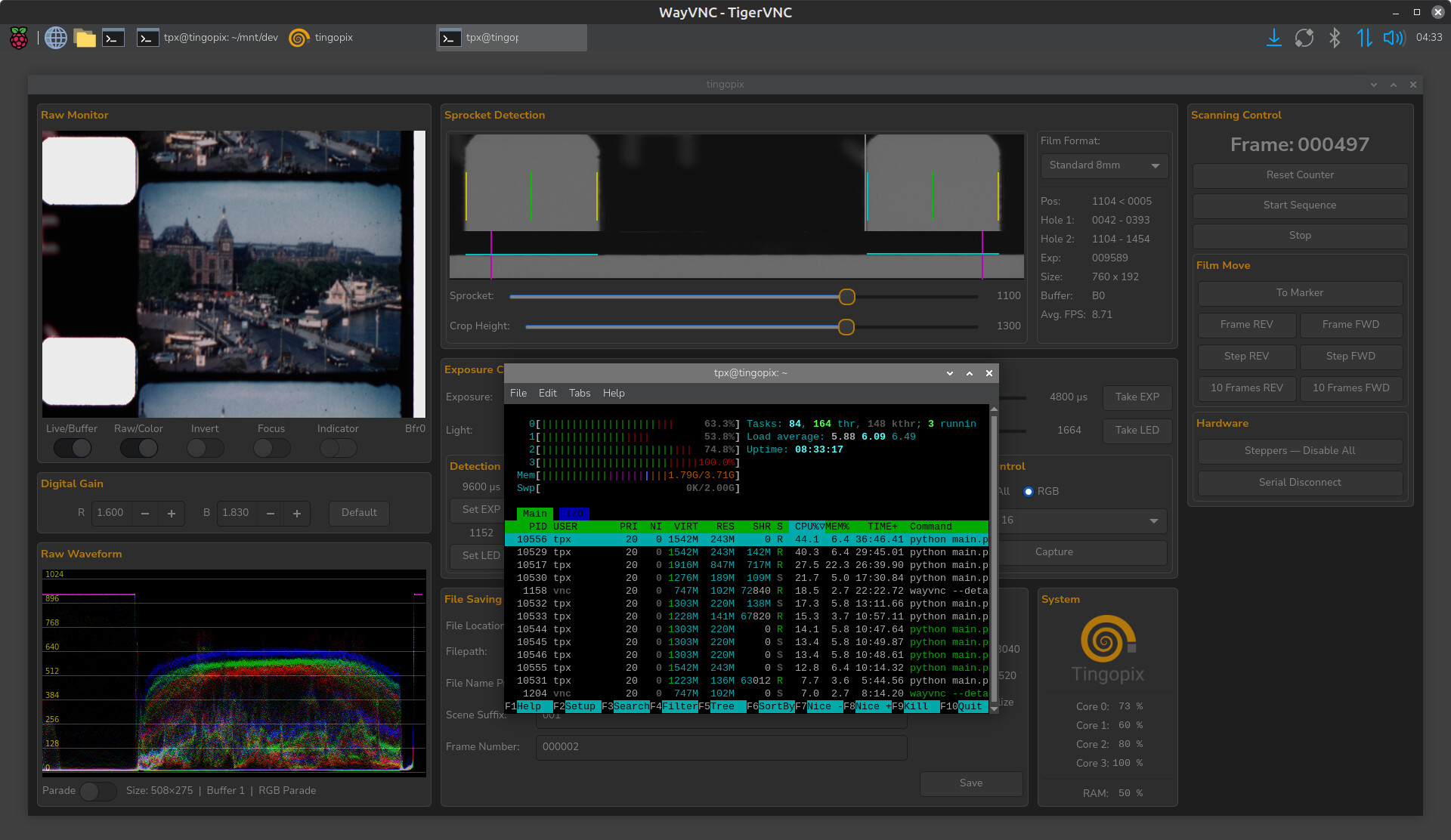
  • Running a practical GUI on a Raspberry Pi 4 via VNC.

The following details describe what is now implemented:

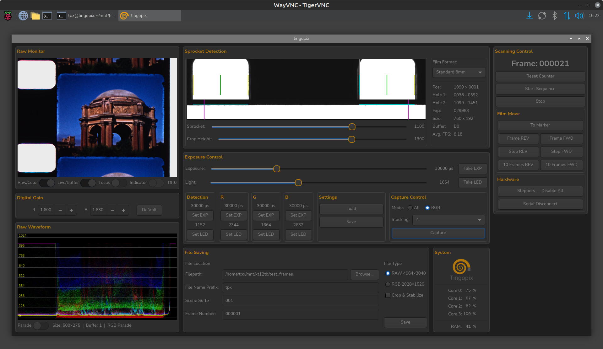
RAW/Color Monitoring Update
The GUI now provides the option to show a RAW or color-processed image and waveform. This is nearly impossible to do with OpenCV (given the RPi 4’s processing power), so here are some of the tricks used to achieve this:

  • Only the RAW capture is used (no RGB image from picamera2).
  • The presented image is 1/16 of the full resolution.
  • Resizing is done by additive averaging, not by scaling. 16 sensel R/B RAW values and 32 sensel G values are summed into one RGB pixel. These are then stored as 8-bit RGB for the GUI monitor/waveform.
  • When using RAW mode, the smaller RGB array is presented.
  • When using Color mode, Black Level Correction (BLC), Clipping, and a Color Correction Matrix (CCM) are applied before converting to 8-bit RGB. These steps occur before storing the data for the GUI monitor/waveform.
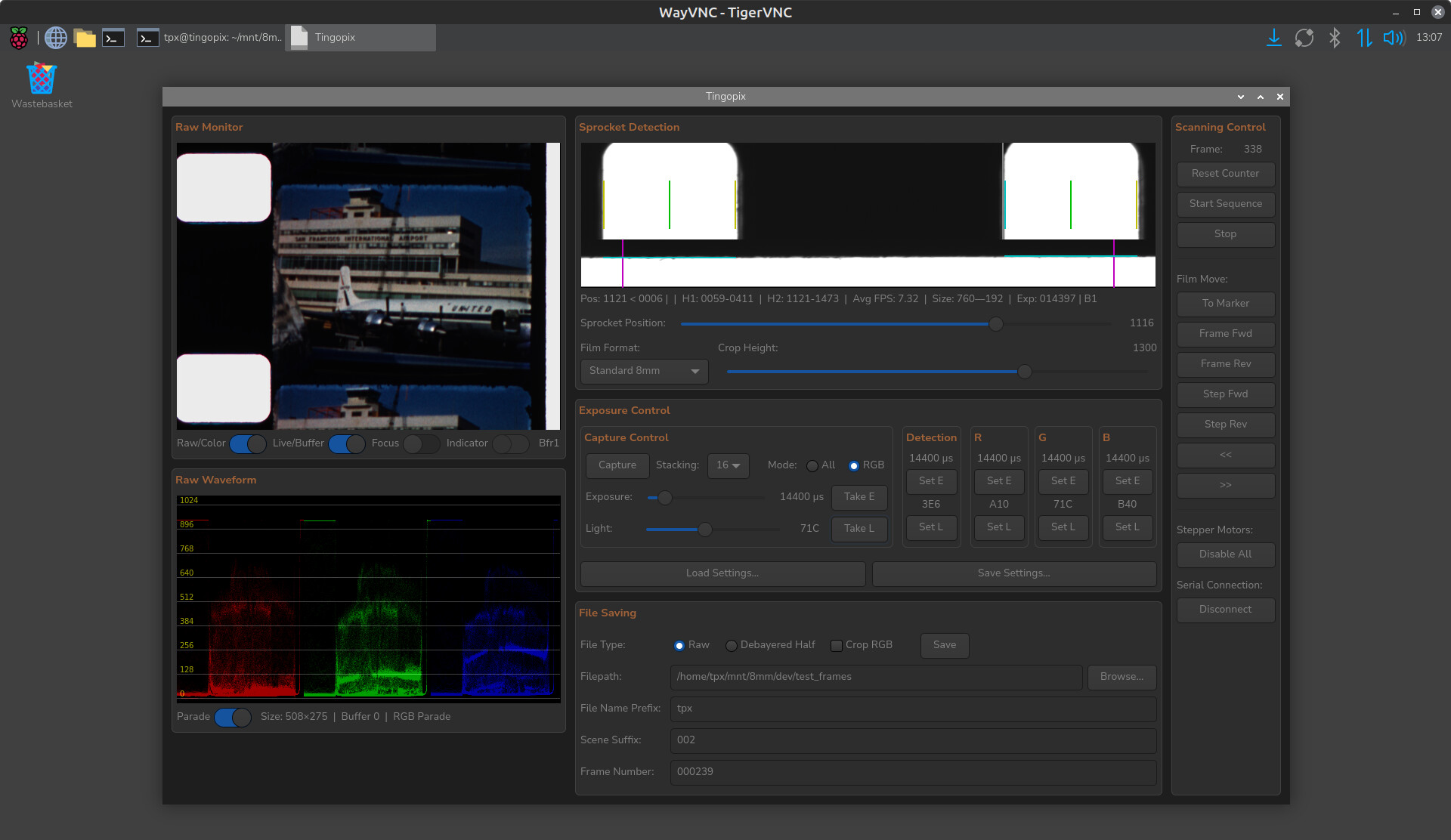
File Outputs

  • The sprocket location data is captured at a lower light intensity and is embedded as a few rightmost pixels in the RAW array.
  • One can save the Sensel-RAW with sprocket data as a 16-bit TIFF (12–16 bit content in the most significant bits).
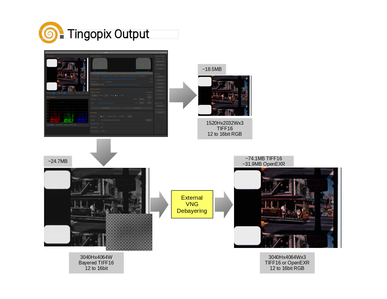
  • Additionally, there is an option to save a smaller RGB image (half vertical/horizontal), with the option of stabilizing/cropping using the film edge or sprocket hole as a reference. This image is created by combining adjacent RB2G sensels into a pixel (every pixel represents true data from the sensor).
  • When full sensor resolution is desired (for example, when capturing 16mm), quality debayering (VNG) would take too long and result in files too large for the RPi to handle. The compromise is to debayer post-scan from the Sensel-RAW mentioned above, which also offers the option to save the result as either uncompressed TIFF16 or lossless OpenEXR (both of which are handled well by DaVinci Resolve).
  • All files are saved as Linear. Gamma is selected and applied within the color correction/editing software.

The chart provides a summary:

How fast/slow?
File saving time is roughly the same for full Sensel-RAW or half-resolution Debayered/Stabilized files. Tests were performed by saving to a hard-disk NAS; performance should be slightly faster when saving to a local SSD via USB3.

  • A single capture of all channels will produce approximately 25 frames per minute (12-bit depth).
  • Capturing each channel separately (different light, same exposure) produces approximately 16 frames per minute (12-bit depth).
  • Capturing with multi-exposure decreases the frames-per-minute rate. The current implementation is not optimized; for a same-exposure/different-light set, it provides 6 frames per minute. Changing the exposure for each channel (an option if no light intensity control is available) takes additional time due to the picamera2 library processes.
  • Post-capture debayering of the Sensel-RAW into an OpenEXR using a vintage 2011 i7 (4 cores) takes about 1.5 seconds per frame (using an SSD).

Retrospective and Future

The scanner is now working at quality levels I could only dream of, particularly considering it uses an HQ sensor. The results are in the same quality league as $30K commercial scanners (though certainly not at the same speed :slight_smile:).

There is always more to be done. From here, my goal is to make minor improvements, clean up the code and pending TODOs, and publish more on GitHub. If anyone wishes to explore building one, that would certainly be an incentive for me to focus less on development and more on documentation.

A call to Cine-Doméstico and a Tscann-8 alternative
I am particularly interested in helping individuals or institutions pursuing the digitization of cine-doméstico (home movies).

Also, if you are considering building a Tscann8, Tingopix is a solid alternative with similar costs (by simplifying to a constant-level LED, which the software already handles). It is simpler to build, provides gentler film handling, and handles both 8mm (400ft) and 16mm (small reels only).

Acknowledgment and Gratitude
The work on this project has been enriched by the exchanges in this forum. Thank you all for sharing your efforts for the benefit of the community.

A special colorful acknowledgment and my sincere gratitude go to Rolf @cpixip for his work with the Raspberry HQ sensor, for sharing his insights into the libraries, and for his invaluable work on the scientific tuning file, which was incorporated into picamera2 and is used in the Tingopix color processing pipeline.

Lastly, it is important to recognize @matthewepler for creating and maintaining this forum, which disseminates know-how and spawns projects like All Film Scanner, this one, and many others.

3 Likes

Yes, by summer I would like to build a scanner and started collecting parts for a tscann-8 2 years ago. Somehow I get distracted by other projects.

I’ve enjoyed reading your progress over the years. Tingopix is attractive because it handles both 8mm and 16mm.

Question: It appears that the the camera mounting bracket just sits on the tabletop with 2-3 kg of mass. I would have thought it would have been screwed down. I’m guessing this design decision has something to do with switching between 8mm and 16mm focal lengths and providing a simple way to create multiple DOFs for alignment. My concern would be stability during scanning; how difficult is the alignment and how often do you have to perform alignment? Could you explain more about why you made this choice?

Thanks for sharing your project!!!

1 Like

@PM490,

My sincerest congratulations on the excellent work and the quality of the results.

Personally, I’ve always prioritized quality over speed. I wouldn’t worry too much about capture times when, as in your case, you achieve such remarkable quality in digitizing our old films.

Best regards.

1 Like

Thank you @Manuel_Angel for your kind words. Muchas gracias!

@justin glad to know you are considering this design for your scanner! and thank you for your kind words.

That is the case, note it is on a heavy glass already. The steel bearings total are 1Kg (2.2 pounds).

Maybe screw the camera to the transport. I do the vertical adjustment with the feet of the mount. It is worth exploring, and maybe move the vertical adjustment to the camera.

A simple way to create multiple DOFs. The switch between 8mm and 16mm is handled by the length of the rail, but some vertical minor adjustments are needed.

I considered the camera-stand into the scanner, the reasons to split transport and camera stand:

  • Hope that there will be other options for the camera, and that changing the camera would not require rebuilding the scanner.
  • Providing the option of using something other than RPi and HQ. The transport/light block is

The setup sits on a very heavy glass table. The alignment is quite simple, the flat front of the camera stand is flat against the front. It is centered to the gap (there is no gate). When switching between 8 and 16, it may need to slightly adjust the leg screws if one wishes to crop one of the sprockets (better resolution on the content). And focusing is not an issue, slide to the 8mm or 16mm range, and then use the knob for fine focus.
How often? usually I focus at the start of the capture. Aligning the stage only when switching formats (or when accidentally moved).
Because there is no gates, as long as it is in the center of the light source, the critical DOFs are focus and height.
What lens do you plan to use? Many on the Tscann are using a microscope lens, but there was a post in the forum making a comparison, and the Componnon-S was better (what I am using know).
There are certainly other ways, the simple (and expensive) is a micro-stage with 3DOFs. I am not mechanical, so the current came out great, but I am certain there are better/simpler options.

Thank you for taking time to answer my questions.

I purchased a Nikon Coolscan LS-4000 ED scanner lens from eBay.

Scanner Nikkor ED 7 Element Lens — Close-up Photography .

I need to make an adapter mount that I can thread into the raspberry pi HQ camera.

1 Like

This looks amazing and really well thought out! I would certainly be interested in building one.
I built a TScann8 last summer (so I already have a lot of parts) but had problems with the sprocket hole detection of the phototransistor. Then before solving it different stuff came up and I never really got it working properly. I am now starting to pick up again on the task of digitizing old home videos from super 8 film and came by this project of yours. Looking forward to see more!

1 Like

Incremental Project Update

Software Improvements

Been working on cleaning the Raspberry Pi Software with the intent to release first and allow those interested to begin testing it.
The software will allow running the camera and do captures even when not connected to the hardware controller (PICO).
A provision to incorporate third party controller/code was also added. For example, it can be used to command a stepper motor in a projector setup. While this requires additional testing, it opens the door to use the software for those modifying projectors (with a controlled stepper).

Cleaner Layout

The cleanup includes a better layout of the gui.

Project Website

A project summary and comparison with Tscann8 is now online. As time permits, documentation will slowly be populated in the project website, pointing to the parts uploaded.
Please visit www.tingopix.com, the actual host is at tingopix.github.io

Stay tunned!

4 Likes

This is awesome, will the hardware parts list be available in the webpage? Also where can we watch sample footage of this scanner (Super 8 and Super 16mm specifically). Thanks for the hard work!

Thank you for the kind words @fabriccio.
Yes, the list of parts, and the files to make 3D parts will be listed in the website and hosted in the github.
Please note that for 16mm, I have only scanned small 3.5" diameter reels (I don’t have any other 16mm film).
You can see the results at https://www.youtube.com/@Tingopix

Here is a 16mm film and a Standard 8mm film.

Speed Improvements

Have been doing some speed improvements, and would like to update previously reported capture frame rates.

  • 16 bit depth/all channels: 16 capture stack, simultaneous capture for all channels (16 camera captures), one light setting = 12 frames per minute.
  • 12 bit depth/RGB: single capture for each color (3 camera captures), each color with its own light setting = 14 frames per minute (more than doubled than before).
  • 16 bit depth/RGB: 16 capture stack, separate R-G-B capture for each channel (48 camera captures), each color with its own light setting = 6 frames per minute (same as previous single capture).

The above -as also mentioned previously- is without camera exposure changes between colors. Different exposure changes for each color channel increase total time by adding the picamera2 exposure timing stabilization for each exposure change.

In summary

Not every reel or every scene may justify the extra time. But when needed, the reduction in noise (by averaging multiple captures) and the increase bit-depth is a significant quality improvement to the typical raw results from the HQ sensor.
The speed optimizations required additional memory use, with a RPi 4 (4GB RAM), htop reporting 1.79G used.

1 Like

Any updates on the hardware list and parts to build this project? I seek to make it but I don’t know where to find the complete instructions. Thanks a lot!

Hi @fabriccio, thank you for your interest.
I do intent to provide a complete list and instructions. The list itself is not the issue, but to prepare all the files (schematics, PCBs, 3D models) required for everyone to manufacture components.
May I ask? are you equipped to build the PCBs with surface mount components or would you order these preassembled?
What I was thinking to do was to release the Raspberry Pi software first, and allow those interested to test it with the camera. That is in part why I have been dedicating more time to polish the user-side software.

Edit: I also see that you have mentioned interest in building other projects, which are very different in cost and capabilities. Have you decided which is best for your application?

As I already own a TScan8 and have knowledge to build many things, I am interested on the software too

Thank you @fabriccio, thats great.

The goal is to have a build plan (similar to what Tscann is sharing) with documentation and files.
I just need spare time to clean, organize, and publish.

Here is a summary list of what to expect:

  • STL Files:
    – Rollers (already in the github).
    – Tension sensor base
    – Tension Capstan
    – Stepper spacers
    – Reel mounts
    – Integrating sphere
    – Camera mount
    – Miscellaneous (reel adapters to 8, S8 and 16mm. Optional lens to film cover)
  • Mounting plates cut/drill CAD Files
  • Schematics and manufacturing files for PCBs (currently)
    – LEDs
    –Controller (PICO and Stepper Drivers)
    – Light DAC
    – LED Driver
  • Key Components
    – Mount plates (currently 3mm thick lasercut plexiglass).
    – 3 NEMA 17 steppers
    –2 Potentiometers (tension sensing)
    – RPi4 (minimum, recommended RPi5) with 3GB RAM or more (would like to test if it runs with 2GB… it possibly could).
    – HQ sensor with cable to RPi.
    – Schneider Componon-S 50mm f/2.4 (camera mount is designed for it) or similar (adjusting the lens support).
    – Edit: Lens thread mount adapters, T42 extension tubes, and M42-T42 adapters.
    – Controller PCB
    — 3 TMC2209 sticks in UART configuration
    — Raspberry PICO
    – DAC PCB (currently 8 port DAC)
    – LED Driver PCB
    – LED Sphere PCBs
    – Components for all PCBs
    – Power supply (currently using more than one to separate LED and motor power).
    – Wiring and connectors
  • Miscellaneous
    – M3 screws and nuts
    – Silicone Rubber bands
    – Misc. Hardware including items for camera slider

I think that’s it… and if you are comparing with the Tscann, note that there is no UV LED or photo detector as sprocket is detected by the camera.

This looks amazing. I would really like to know the approximately price of this build and also know when everything will be published to start the build

You had stated earlier that your scanner

compared to the T-Scann. What is it about your design that allows for better handling? I don’t know much about this aspect of projectors or scanners. Apologies if the answer is obvious to others.

@fabriccio thanks again for the kind words.

The project was developed through a number of years and prices have changed particularly after tariffs for US. Without repricing, a rough estimate would be between US$600 and $800 (considering the Rasberry Pi, camera, and eBay lens).
When will everything be published? will do my best to publish everything within 4 months… but it may take a bit longer.

@justin no reason for apologies, and good question. Notice the word I use was gentler.

The Tscann uses a pinch roller (pressure contact on both sides of the film) and some parts of the film path take sharp turns. I have some film that it has deteriorated, and a sharp turn will make it crack. It is not unique to Tscann, the Gugusse roller also uses a pinch roller.

Why Tingopix is gentler?

  • Pickup and supply tension is set/maintained by controller.
  • Friction-capstan. There is no pinch roller, the capstan holds the film solely by friction under tension.
  • Larger diameter rollers when turning more than 90 degrees.
  • Minimum contact with film. All rollers and capstan have contact only on the film edges (green bands for 8 and 16 mm gauge).
  • There is currently no gate… the film is never in full contact with any scanner component, only edges.

For the above reasons, I do think this design is gentler.

But is the handling better than Tscann? I have not built or test a Tscann, so there may be some advantages to it.

I wish everything could potentially be published faster haha. We are currently also looking at the Axion Scanner from Cuimaging because the build looks solid and also faster, but specially it’s ready to purchase.

I really like all the projects in here but no one really has everything organized for others to build their amazing scanners :disappointed_face:

@fabriccio It looks like a well-built new scanner, and a new commercial price range. The cost certainly has a return on the speed, larger reels, and options.

My goal with Tingopix is to be an affordable option especially for non-profit archives, without quality compromise. To that effect, I would point out that the bit-depth output is 12 to 16, and the DAC used for light dimming is also 16-bit. Not bad!

1 Like

Is there any way to build just the rollers stl and the light source right now? We are modifying our current setup on the Tscan8 not only to fit 16mm but also to handle better the whole roll. That would help us a lot l.