Strange encounter in the red channel/RPi HQ Camera

While scanning Agfa Moviechrome Super-8 footage with the Raspberry Pi HQ camera in raw-mode, I encountered something interesting.

The following frame

was developed via RawTherapee in the default settings. Note that there is slight banding in the blue sky portion of the image. The raw file (.dng-format) can be downloaded here if you want to check on your own.

The scan was exposed in such a way that while the sprocket area blows out (100%), the brightest image areas are still captured faithfully (<90%). The camera was operated with the picamera2 lib which created directly the raw image.

So far I have traced the banding issue back to a very high film density in the red channel of the raw file. Here’s that red channel, somewhat enhanced via daVinci

Note the very dark area in the blue sky. This area of the image is in fact noticably darker than the unexposed film around the sprocket area!

Similar behaviour can be seen in other areas of the capture, for example in the dark bushes on the lower right side of the frame (here, also the noise of the HQ camera is quite visible).

I think what I am seeing here could be the special chemistry designed by the Agfa engineers. In order to create vidid cyan color, maybe they intentionally reduced the red channel in high cyan saturation areas?

I have noticed a similar thing with Kodachrome film stock, again only when vivid cyan colors come into play. However, it is way less noticable.

In fact, in both cases, Moviechrome and Kodachrome, going from the raw files to the color-graded end result, the described effect is practically not noticable.

Another explanation might be that the color science of the HQ camera is not perfect. If too much blue and green (=cyan) is subtracted from the red channel (which can happen with the color matrices coded in the tuning file), this would lead to negative values in the red channel. Which of course cannot be represented by any raw format. The more I think about it, that could actually be the issue.

An easy fix would be to reduce the saturation slightly during scanning. It was at the default value for the example shown. But maybe the color matrices need to have some further examination…

I would be interested if some members of the forum could comment on that phenomenon.

I think all of the information is there in the DNG file. I just processed it (with Photoshop’s “Camera RAW” app) and I don’t see the banding between the cloud/haze layer and the open sky that you did:

At first it was hard to choose between having red information and blowing out the highlights on the mountain vs. losing the red but having more contrast on the mountain.

I settled for a custom curve on DNG import which let us have both:

curve

Then it was just a quick “auto tone” operation to pull each channel’s histogram out to its limits (along with a little denoising and an unsharp mask; I can’t help myself) to get the above image. It’s probably still a little over-saturated, but Photoshop’s “auto tone” has a tendency to do that.

If you inspect the channels in the JPEG, the conversion to sRGB butchers the red channel in the sky completely. So, here is the sky before the sRGB conversion via a screen-capture in the image editor (while it was still in “Display P3” color space):

That seems reasonably continuous for the kind of haze that was over the mountain.

EDIT: I just repeated the process but imported the DNG in the “ProPhoto RGB” color space instead of P3 and that gave enough headroom that I didn’t need to mess with any curves in order to get a continuous red channel that could be worked with. Exporting as 8-bit sRGB still crushes it down pretty hard though.

2 Likes

Many thanks @npiegdon! I think we are coming closer to solve this riddle.

Inspired by your tests, I wrote a little program to extract the raw Bayer data of the raw, that is, the red, green1, green2 and blue channel. Now if you look at the slightly brightened up red channel image, you see the following:

Indeed, there is a image data available in the sky band! I measure values of around 5300, that is, about 1200 counts above the blacklevel. One can see this also in the little histogram here (the leftmost large spike):

histogram

Reducing the contrast in RawTherapee (RT) to -47 and using “No profile” in the “Color Managment”, I get something not so good:

The too dark band is back again! Note that this is very similar to the red image above, which was obtained with the daVinci raw image reader. It is also very similar if you read the image with rawpy, a package which uses dcraw as a base, if I remember correctly.

Back to RT - switching RT to using “Camera standard” I end up with this red channel:

“Camera standard” should be a color matrix supplied by libcamera, using the information from the camera tuning file.

Lastly, Jack Hogan once developed fine-tuned color matrices for the HQ camera. Using his “Raspberry Pi High Quality Camera Lumariver 2860k-5960k Neutral Look.dcp” with the “Custom” checkbox enabled, I end up with the following:

Amazingly, the whole sky is now too dark in the red color channel! Most interestingly, this last case would be hard to spot, as there is no obvious banding in the sky.

So in summary, the issue seems to stem from the different ways to convert raw data into the (linear) output file where the rec 709 is applied to. There are only three steps involved here (if I remember correctly):

  1. Subtract the black level (I assume this is handled correctly by all programs tested)
  2. Apply WB - which is just multiplication in the red and blue channel by some factor (can not possibly introduce the behaviour seen above)
  3. Apply a CCM color matrix - here, there are negative entries which can lead by saturated colors to values drifting below zero. Those values cannot stored or further processed and are maybe the core problem

Which CCM is applied depends; in the .dng-file is a CCM embedded, namely the one libcamera calculated from the CCMs in the tuning file. So this is probably the “Camera standard” case in terms of RT syntax.

I assumed that the “No profile” selection would just use an identity matrix. But the result clearly differs from from my first image, which is indeed the raw red channel, even without the black level subtracted.

Lastly, the “Custom” selection allows you to choose .dcp-files. The one I used contains mainly two CCMs, for 2860k and 5960k; the matrix which is really used is interpolated from the color temperature set for the image.

Summarizing: the effect seems to depend on the CCM employed. Which one is actually used seems not really documented well. You might occationally end up with funny banding artifacts in highly saturated imagery.

So again @npiegdon, thanks for the input! If other members have fun to try their luck on this test image, please post the results. Would be interesting to see how other software handles this case.

2 Likes

The jpg below wer produced by changing the RGB curves of the DNG with Darktable.
I see banding on the right side (unexposed area) of all 3 channels. Yet on the left side (above/below the sprocket hole) there is no such banding.


I do not know what the origin of this particular banding (only on the right side) may be.
I have seen similar banding profile across the entire frame due to noisy power source for the light, but the fact that it is only on one side of the frame seems to exclude that out.
If I may speculate, it feels more like a sensor noise issue than a computational byproduct. Again, pure speculation.

1 Like

Thanks @PM490 for the observation! I think this is just sensor noise. It is highly unlikely that it is caused by the light source. The “light source” are three independent but identical light sources, driven by independent constant current sources. Any intensity variation would have to be sync’d with the line frequency of the camera. As this is a completely different circuit, I do not see any way how such a sync might happening.

This streaky noise pattern was discussed in the exposure fusion vs. raw capture thread and I have seen it in across the full frame (if that frame is dark enough) over the full area of the frame. It’s mainly present in the red channel, as this channel works with the highest overall gain of all color channels.

Usually spatio-temporal noise reduction gets rid of this noise.

1 Like

@PM490 - you started me on looking further into this noise issue. Here’s a .dng capture (scanner settings as above) which basically only shows a rather dark frame. (Note that this is only a scan of a dark header film; a dark frame of a Kodachrome would be even lower in amplitude, but I do not have such a scan at the moment.)

Looking again on the red channel (enhanced to make structure more visible)

one instantly can verify your observation: the amplitude of the bands are increasing from left to right.

A wild guess would be that this is happening in the analog part of the read-out circuitry of the sensor, being somewhat reset once a full scanline is processed.

Actually testing the above (enhanced) image in more detail, here’s a plot of a vertical line (red) on the right (diagram “Intensities”)

and here the same, with a line on the left:

the difference is less noticable, but there are higher spikes in the signal on the right side of the frame.

Here’s another raw scan for experiments. It’s Kodachrome stock and shows a rather dark scene. The intensity plots do also not show a too much difference between left

and right borders of the scanned frame

In summary, the sensor noise we are talking about is certainly there, but I think it is especially visible to the human eye because of the correlation in the horizontal direction.

In the second .dng-file there is a tiny dust particle in the center top part of the frame. It gives a sort of reference of the performance of the optics/sensor/software-combination of the scanner used in comparision to the film grain at low exposure parts of a scene. I’d say that the spatio-temporal noise introduced by film grain overwhelms sensor noise by far.

1 Like

A couple of thoughts…

  • If two captures are taken/processed with the same settings of the unexposed frame… are the horizontal lines in the same vertical location?

  • Is there any difference on the horizontal lines if noise reduction is on and off?

On the last one thought, I would hypothesize that the noise reduction is then operating differently in the lower black levels (right side of the previous RGB frames) than in the slightly higher black levels (like the left side of the previous RGB frames).

At the moment I have my setup offline, but when able I will also test the lower black levels to see what I find.

Hi Pablo (@PM490) - I did some quick captures of the test you have suggested.

I used the standard app to capture that stuff because I do not want to rewrite my own software. Here are the command lines

01: rpicam-still -o cap_01.jpg -r --shutter 3594 --gain 1.0 --awbgains 2.89,2.1 --denoise off
02: rpicam-still -o cap_02.jpg -r --shutter 3594 --gain 1.0 --awbgains 2.89,2.1 --denoise auto
03: rpicam-still -o cap_03.jpg -r --shutter 3594 --gain 1.0 --awbgains 2.89,2.1 --denoise off

So 01 is the reference, set up like I would operate the HQ sensor in my software, 02 includes a denoising step, and 03 features the same capture parameters as 01.

You can download here cap01, cap02 and cap03 for your own analysis. I intentionally dimmed the light source to get in the area of image intensities we are interested in.

Here’s the (enhanced) red channel of the reference cap01:

The same behaviour can be seen as previously: noisy streaks, primarily on the right side of the image

Comparing this with activated noise reduction, we obtain

Hmm. Barely a difference. Maybe the noise reduction works only on the generated jpg? The captures were done with a RP5, and here a lot has changed under the hood…

Anyway, on to the final test image, cap03 which was taken with the exact settings of cap01:

Not much difference either. But: the visible noise structures did change between cap01 and cap03 - so I think it’s something of a hardware related noise. Note that Jack Hogan did quite some research on the HQ sensor and it’s noise characteristics, hinting to on-sensor noise cancelation techniques.

1 Like

Thank you for doing the test.

Looks like that is the case. When my setup is back, I will do some testing to see what it shows and have a point of comparison.

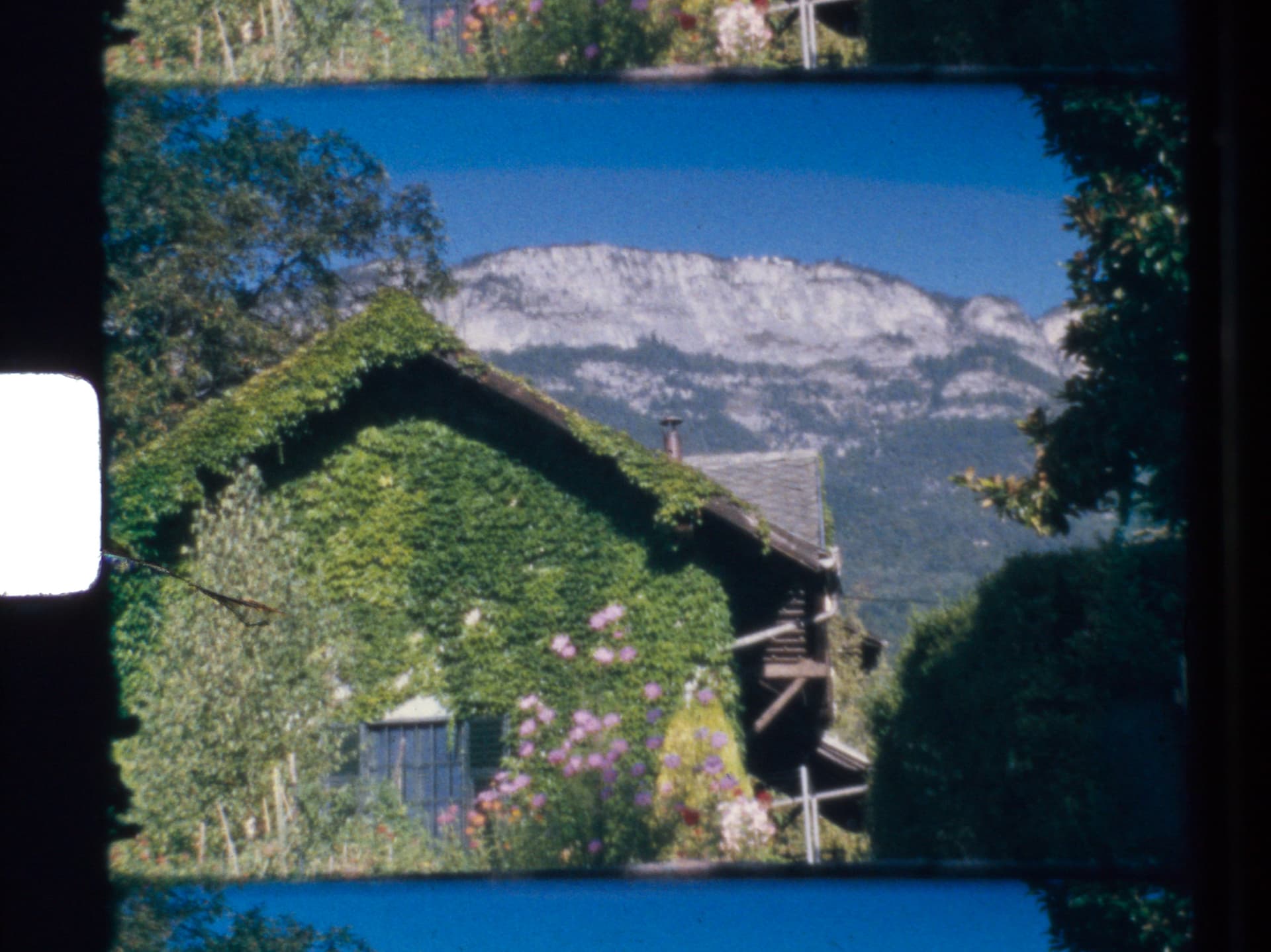
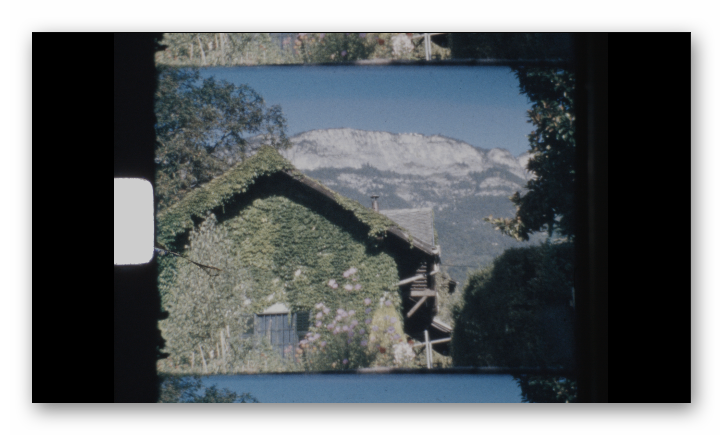
Let’s return to the original question - the strange banding in the blue sky in a Agfa Moviechrome scan (first post of the thread).

First a summary, as this is going to be a long post: The colors available in film stock greatly exceed the colors representable on a normal computer display (rec709 or sRGB). Mapping from the film stock to digital imagery requires a careful adjustment of the process in order to preserve the color content of the original footage.

Now for the details.

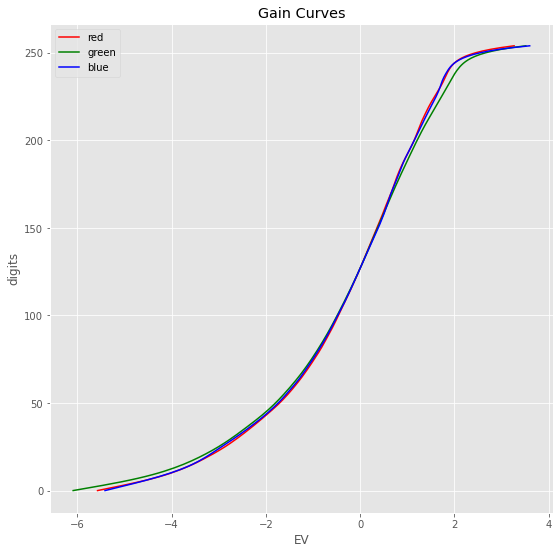
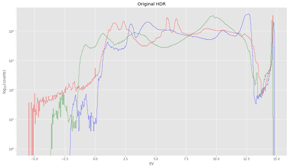
To get a basis for analysis, I created a real HDR from an image stack of 32 different exposures of the frame, ranging in exposure time from 0.24 msec to 0.3 sec. I used that data within the context of Debevec’s algorithm to first estimate the gain curves of my HQ sensor. This is the result:

That plot shows two things: first, the estimate of the gain curves is not too off (it would be perfect if all curves would fall onto each others), and secondly, your average jpg covers about a range of 8 stops.

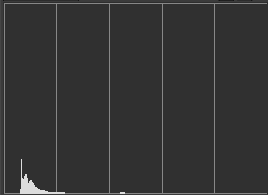
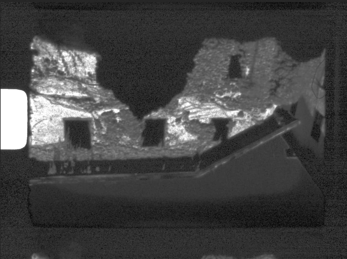
Now, using the gain curves to calculate the real HDR, one ends up with image data having the following histogram:

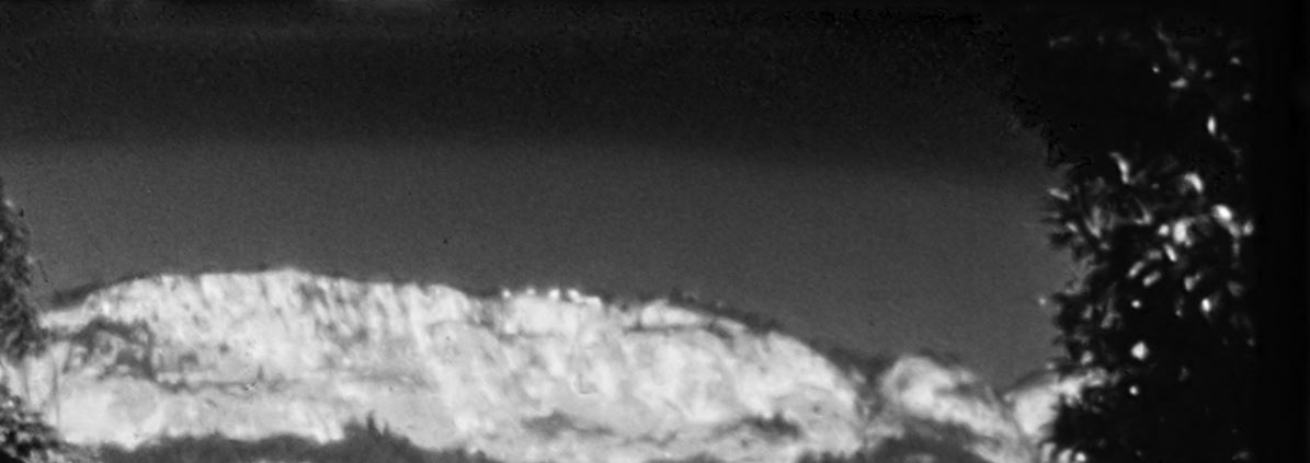
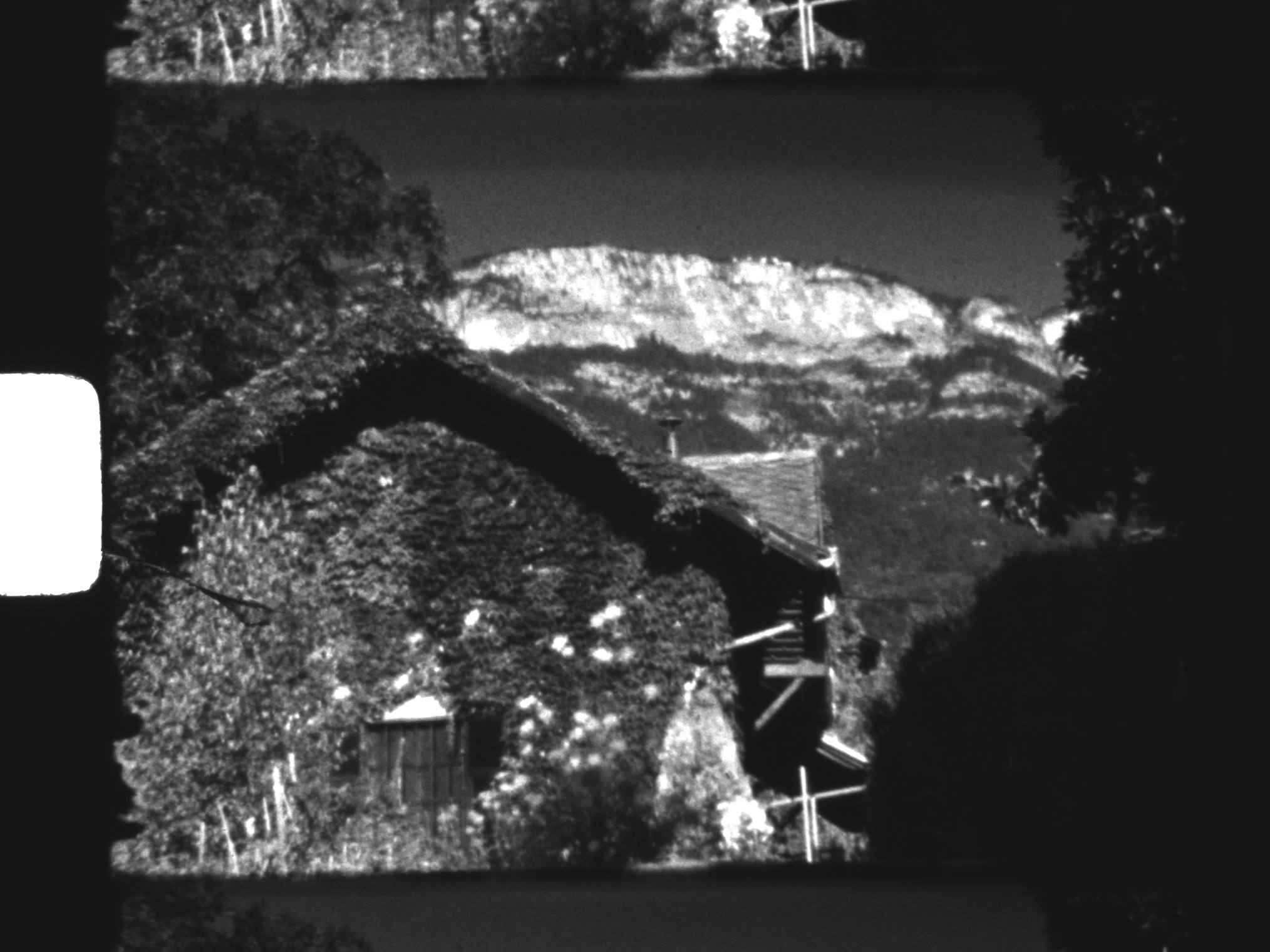
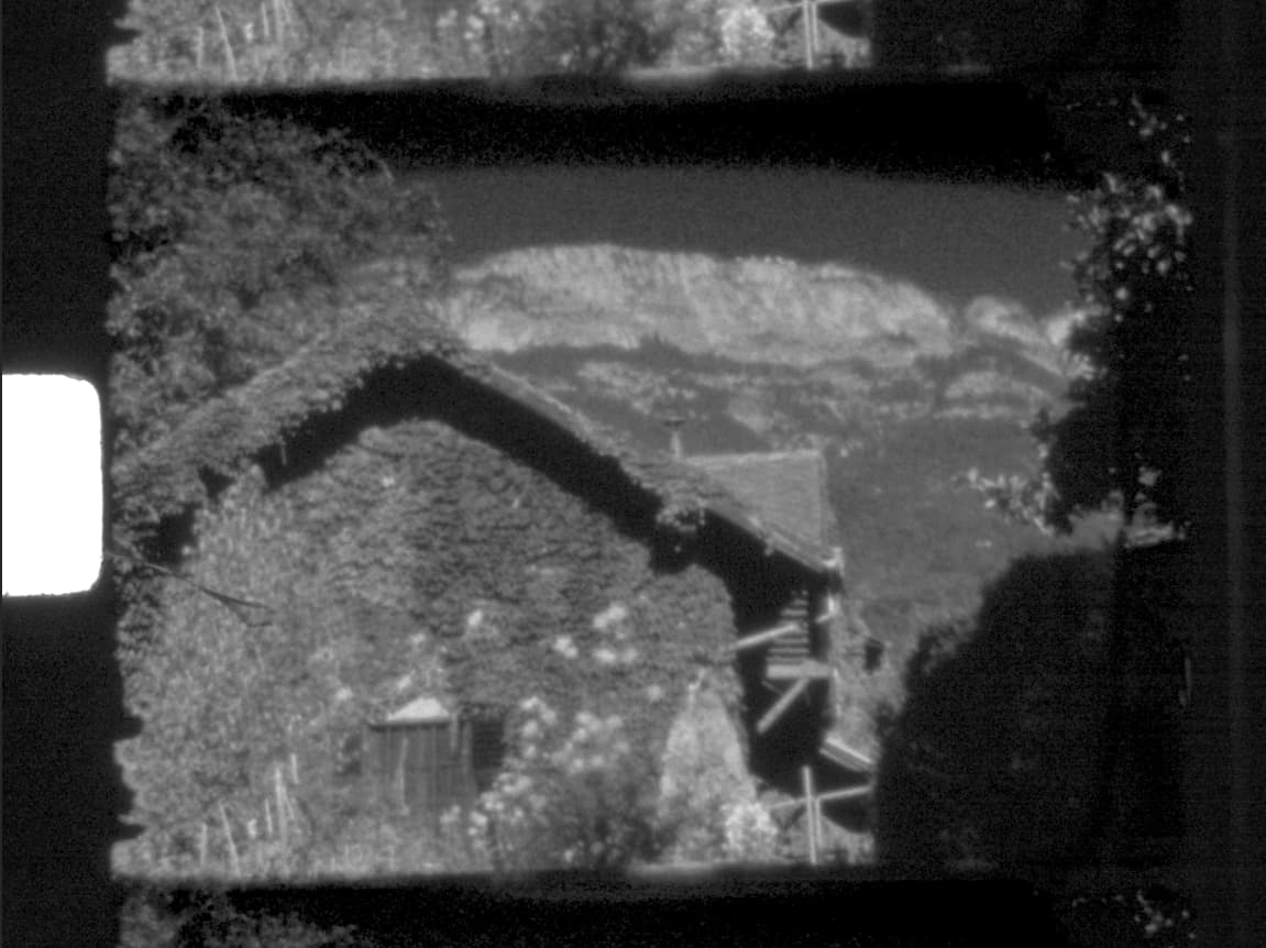
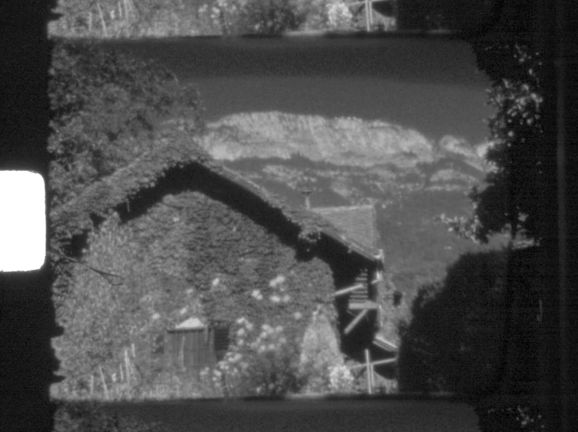
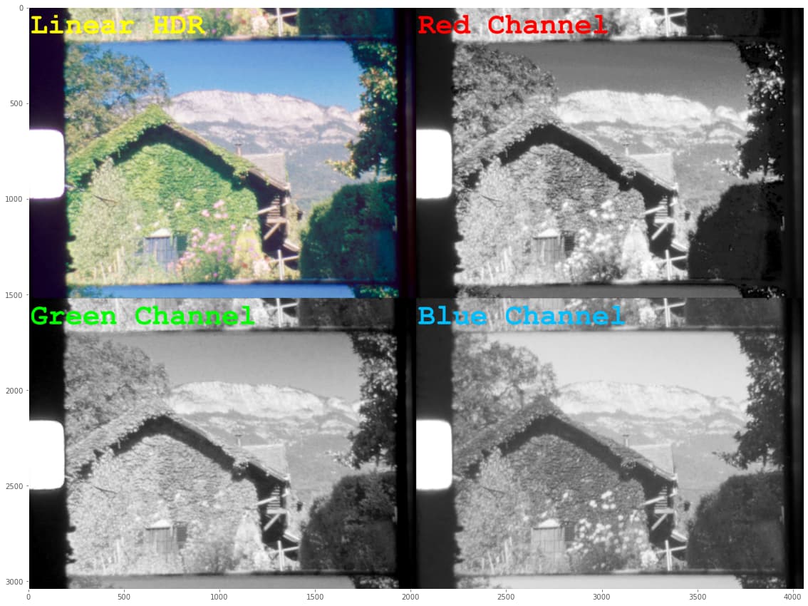
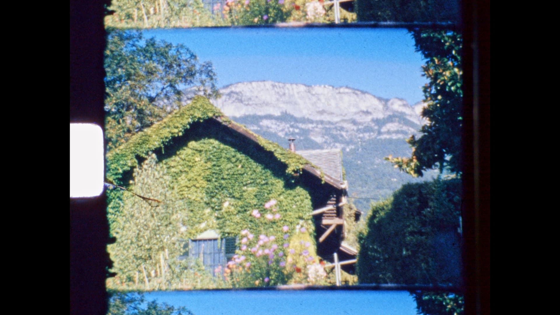
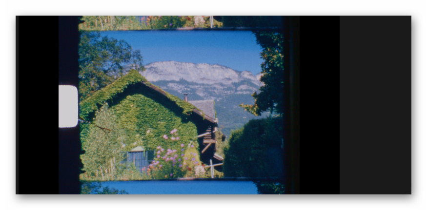
I find this rather impressive - the data of the scan ranges over 20 EVs! Well, granted, the real image data ranges probably only over 12-15 EVs (stops). Here’s a display of the HDR-result:

Looking at the data in the sky, there are slightly visible bands of different color as well. So it’s safe to assume that the banding is actually real, sort of. The question is: why is it so much more visible in the .dng-file when developed by the usual raw converters?

To answer this question, I implemented the raw development pipeline step by step and checked the data after each step.

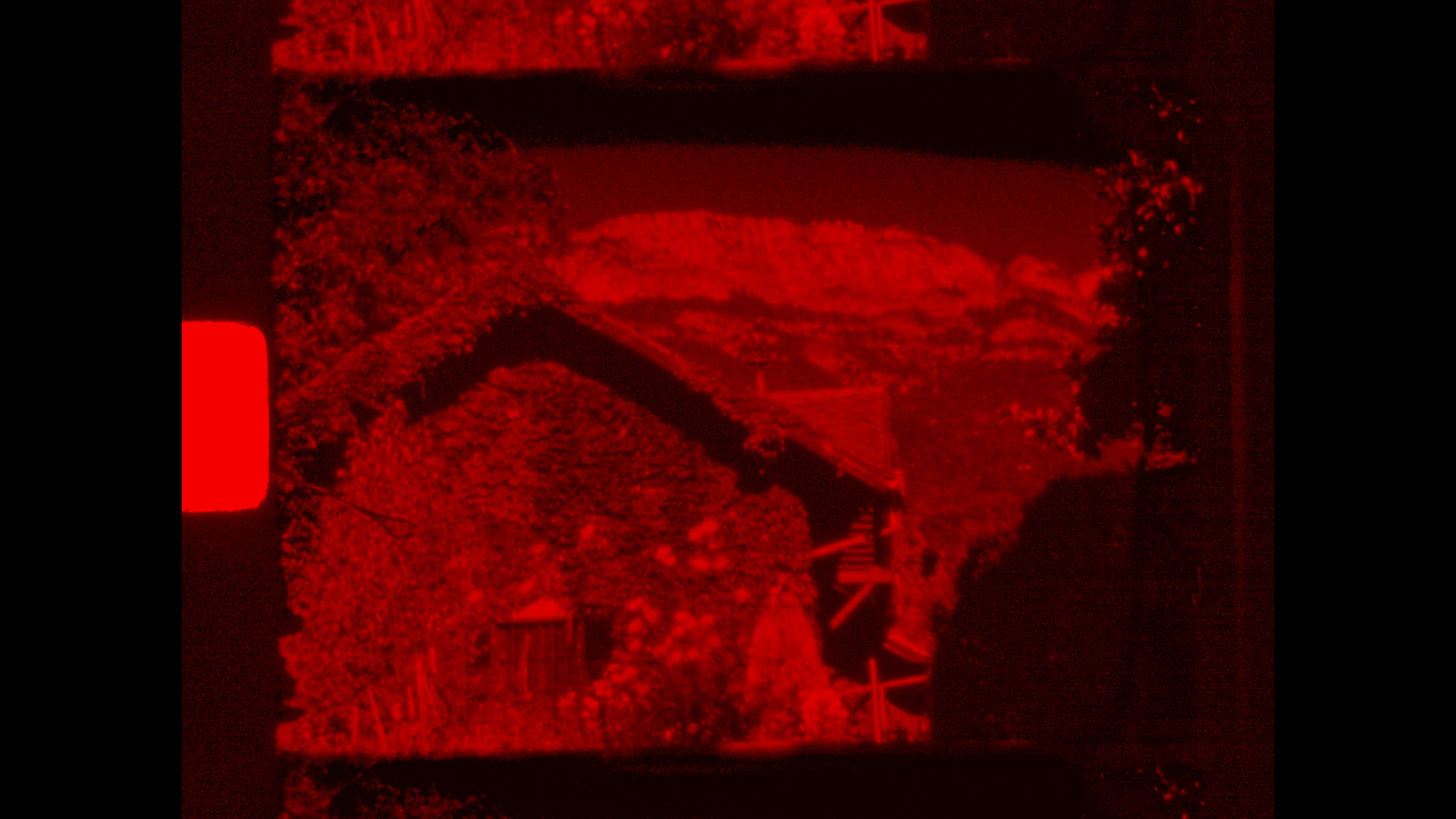
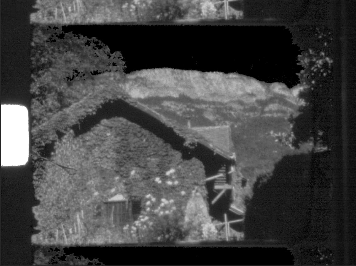
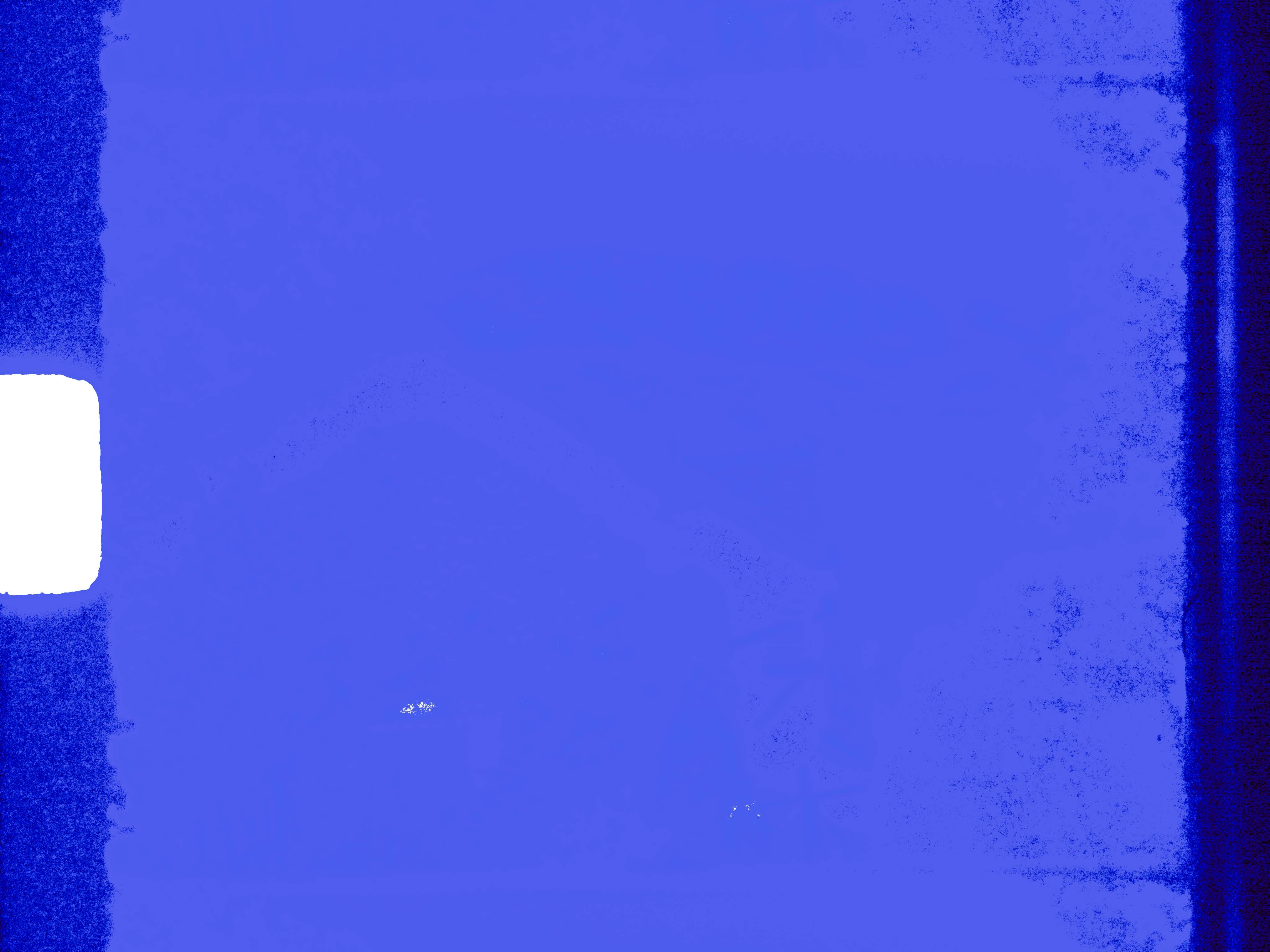
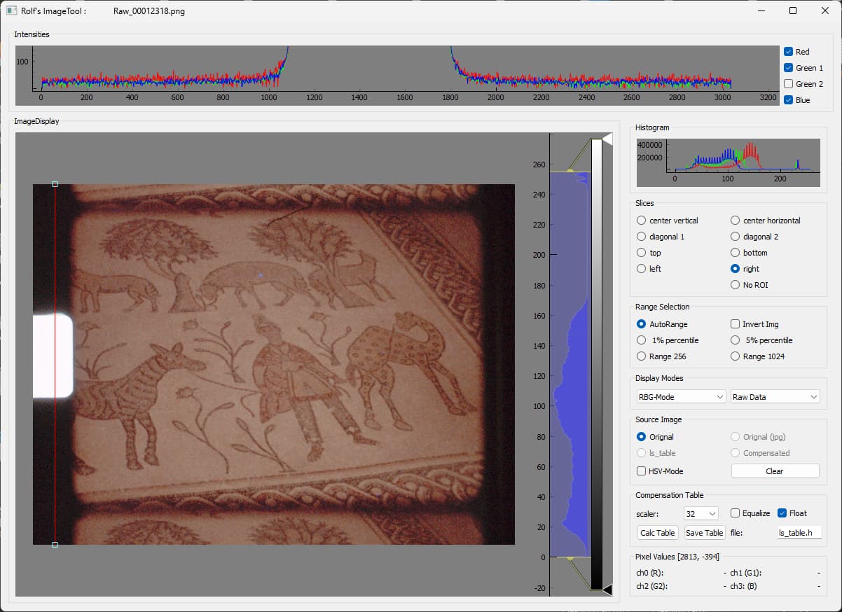
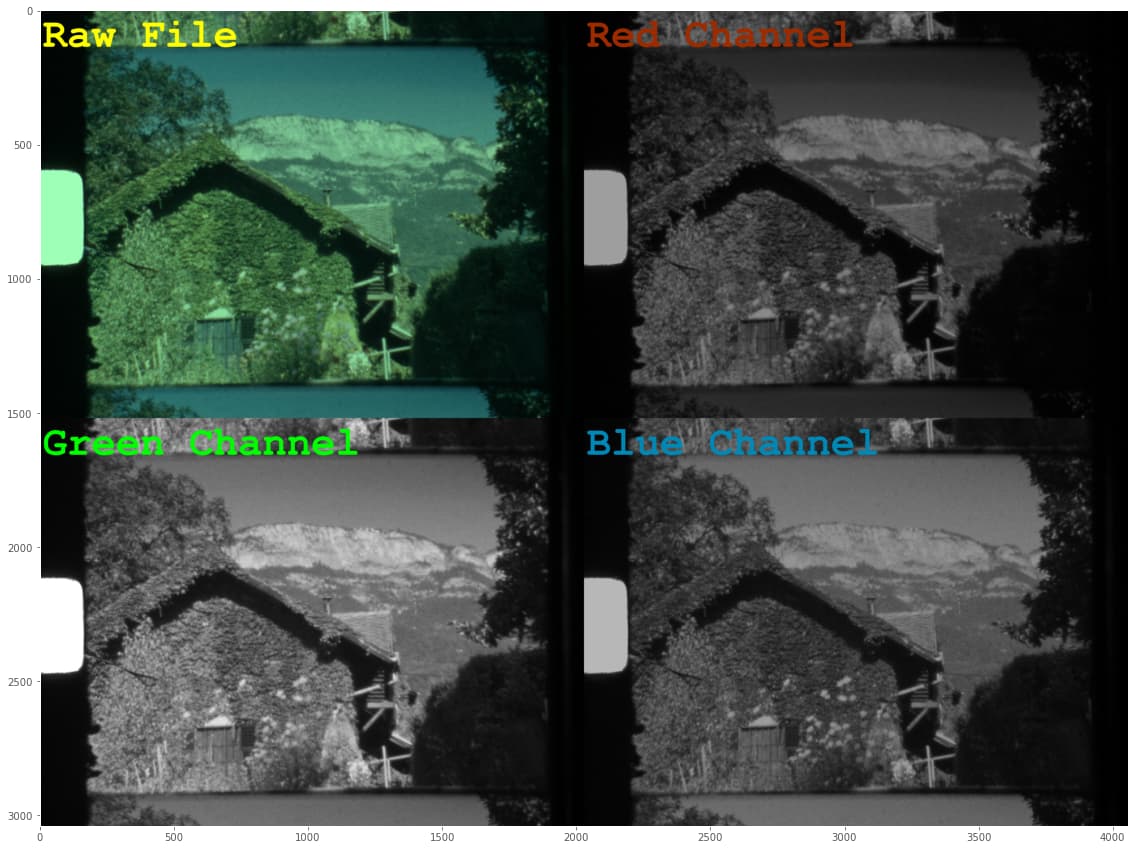
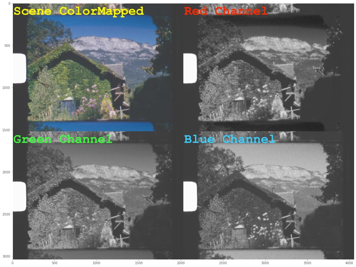
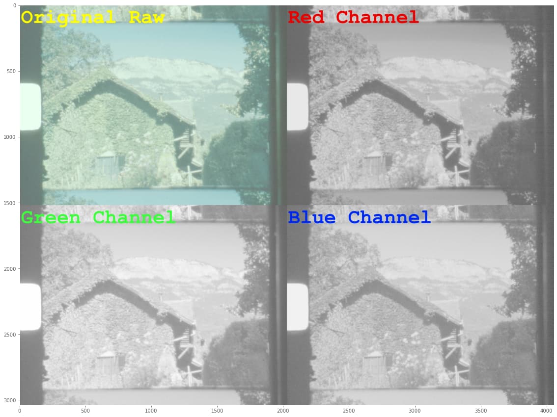
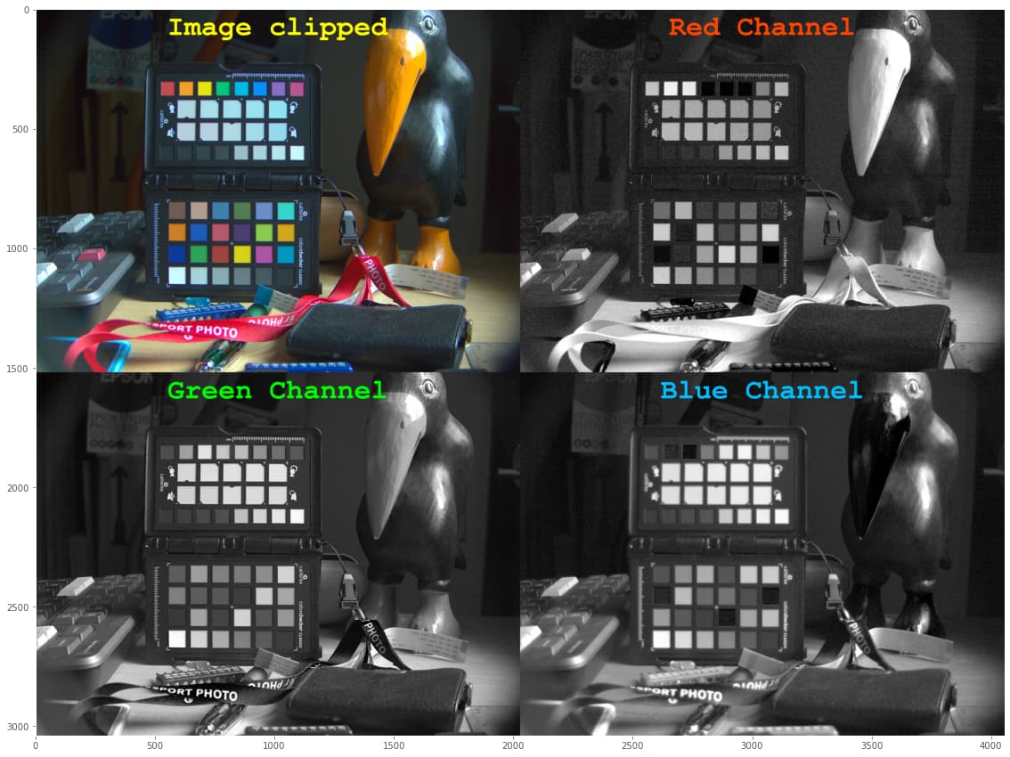
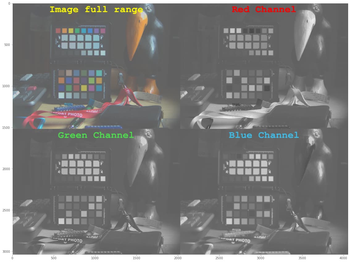
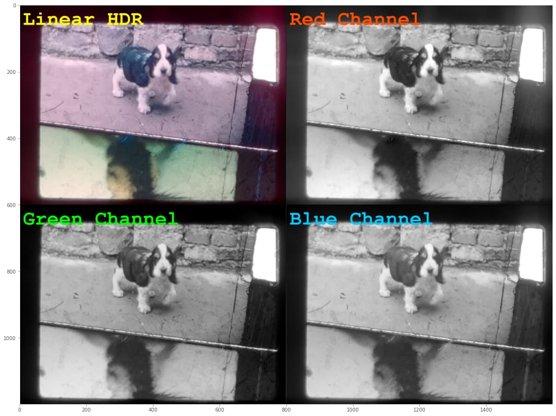
Now, the very first step in raw development is to De-Bayer the image. During that process, also the blacklevels and whitelevels are taking into account, in effect normalizing the image data. Here’s the result of these steps:

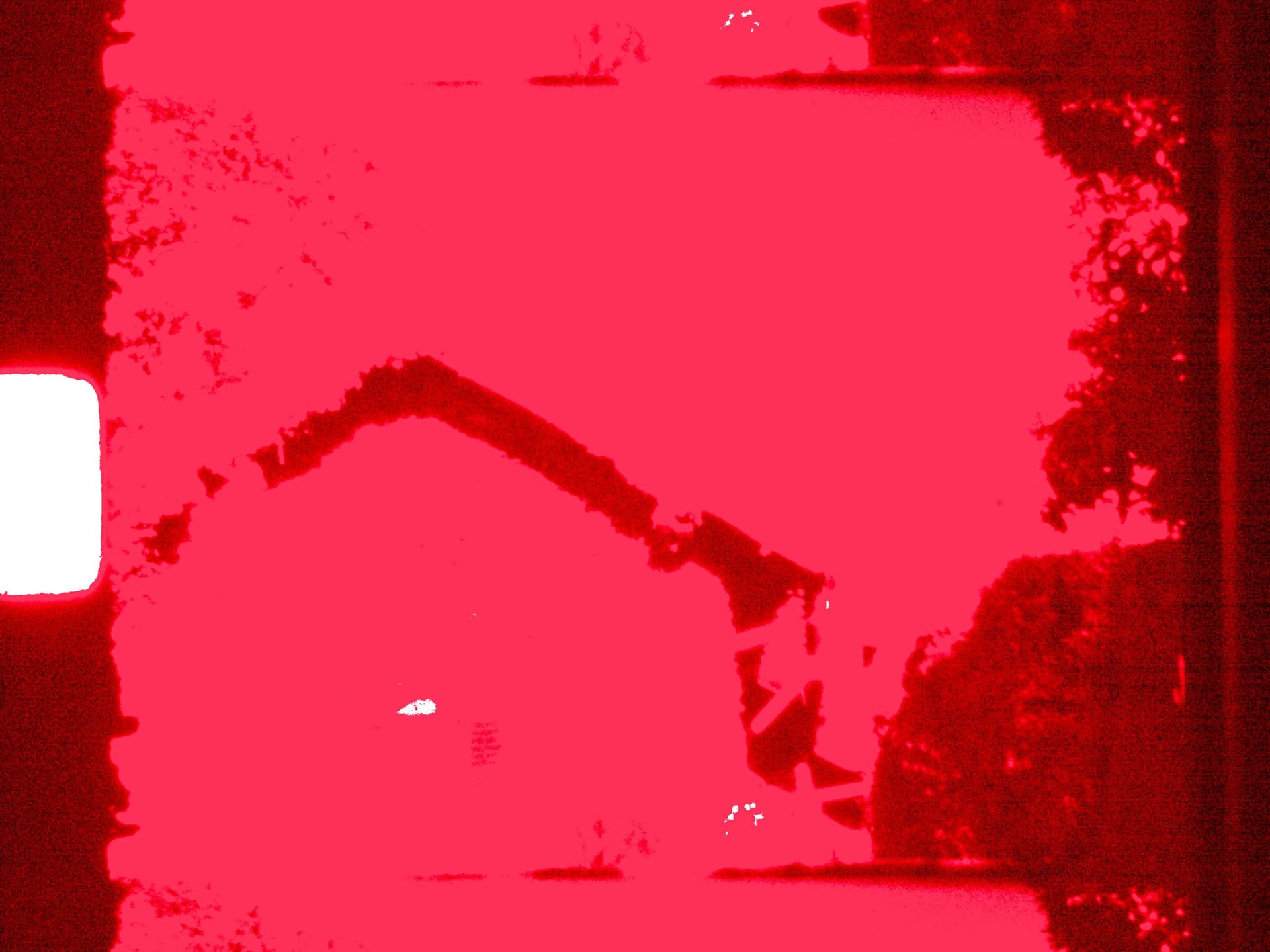
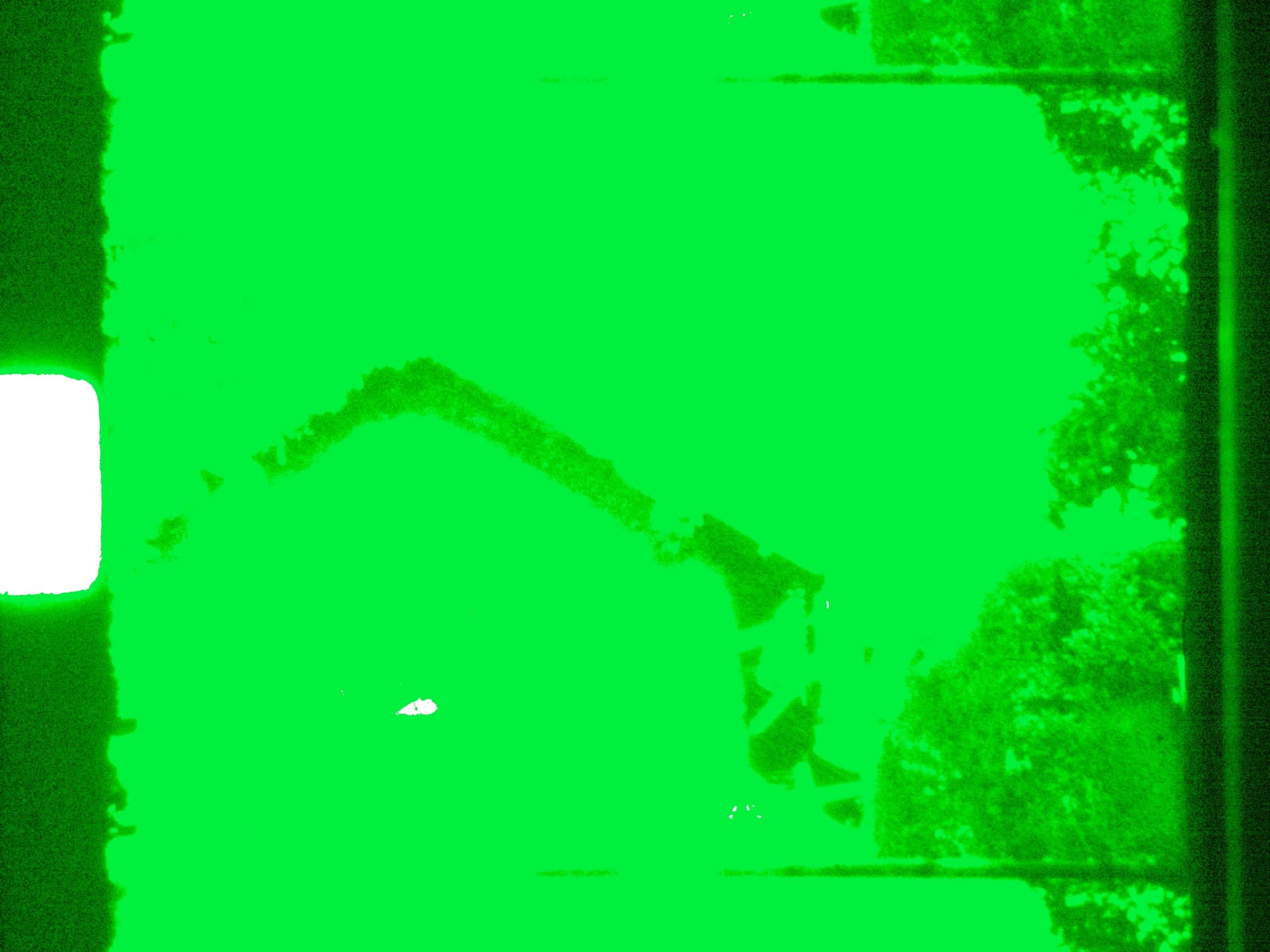
On the top left is the obtained image, it features the familiar greenish tint of raw data not yet color managed. The other quadrants of the plot show the data in the red/green/blue channel, and one can see in the sky two nice bands in the red channel of the data.

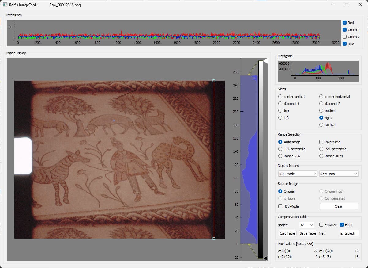
As a sidenote: already at that step some colors will be clipped. Some clipping is intentional (in order to avoid magenta tinted highlights), some other not so much. Specifically, from the raw data the blacklevels of the sensor are subtracted - which in the case of the HQ sensor have a value of 4096 units. That information is contained in the .dng-file for the raw converter to use. However, the lowest value available in the raw Bayer-data are red: 3920, green1: 4032, green2: 4016, and blue:3986. So subtracting the blacklevel as specified in the dng-file will yield negative values of some pixels of the image. Not so good, but I think all raw converters handle that situation gracefully. There are no visual artifacts in the above image either.

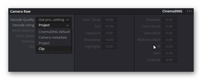
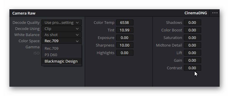
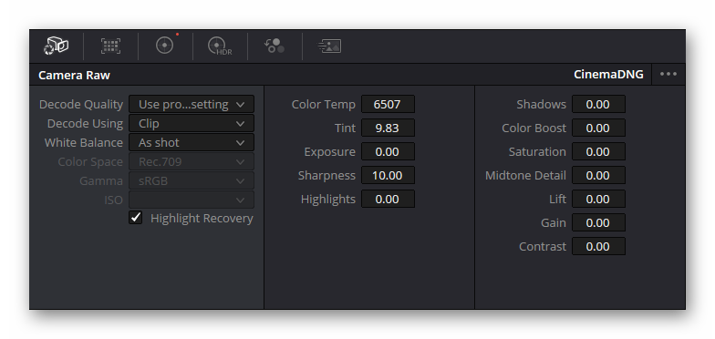
The next step a standard raw converter is performing is applying the whitebalance coefficients used at the time of capture to the raw data. In the case of the HQ sensor, this is either the inverse of the red and blue color gains you specified when taking the capture, or, worse, the inverse of the color gains libcamera came up with at capture time, based on the information available in the tuning file. None of this will happen if you specify the whitebalance in your raw converter by manual means, for example using the color picker to indicate a grey surface in the image.

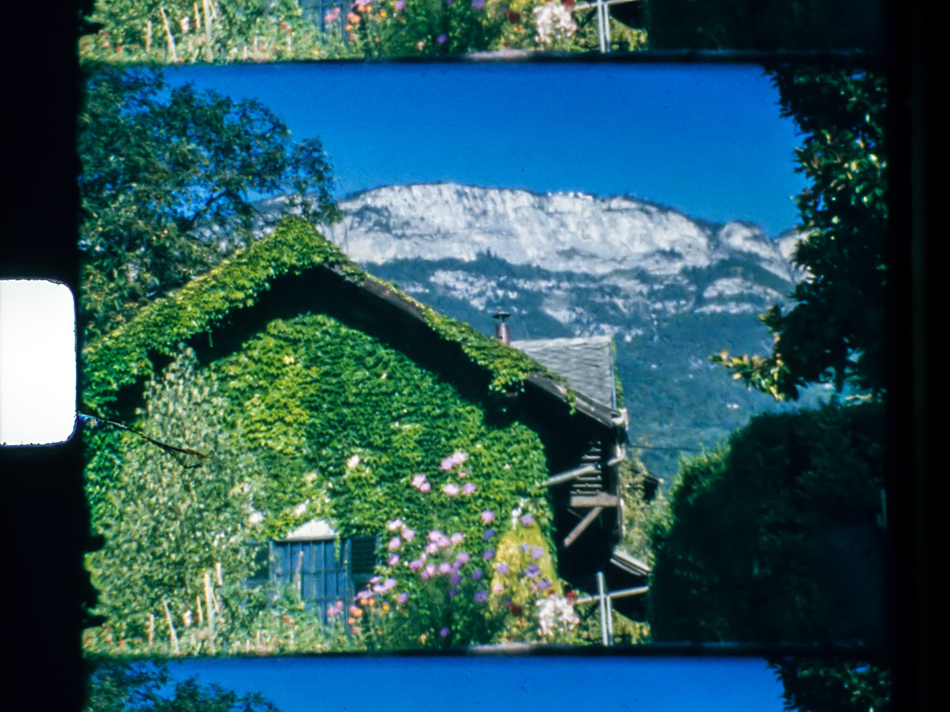
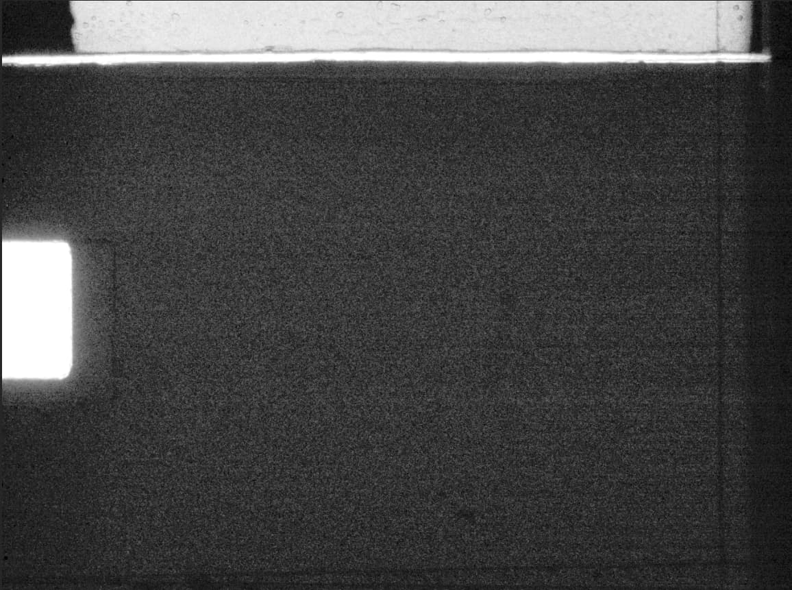
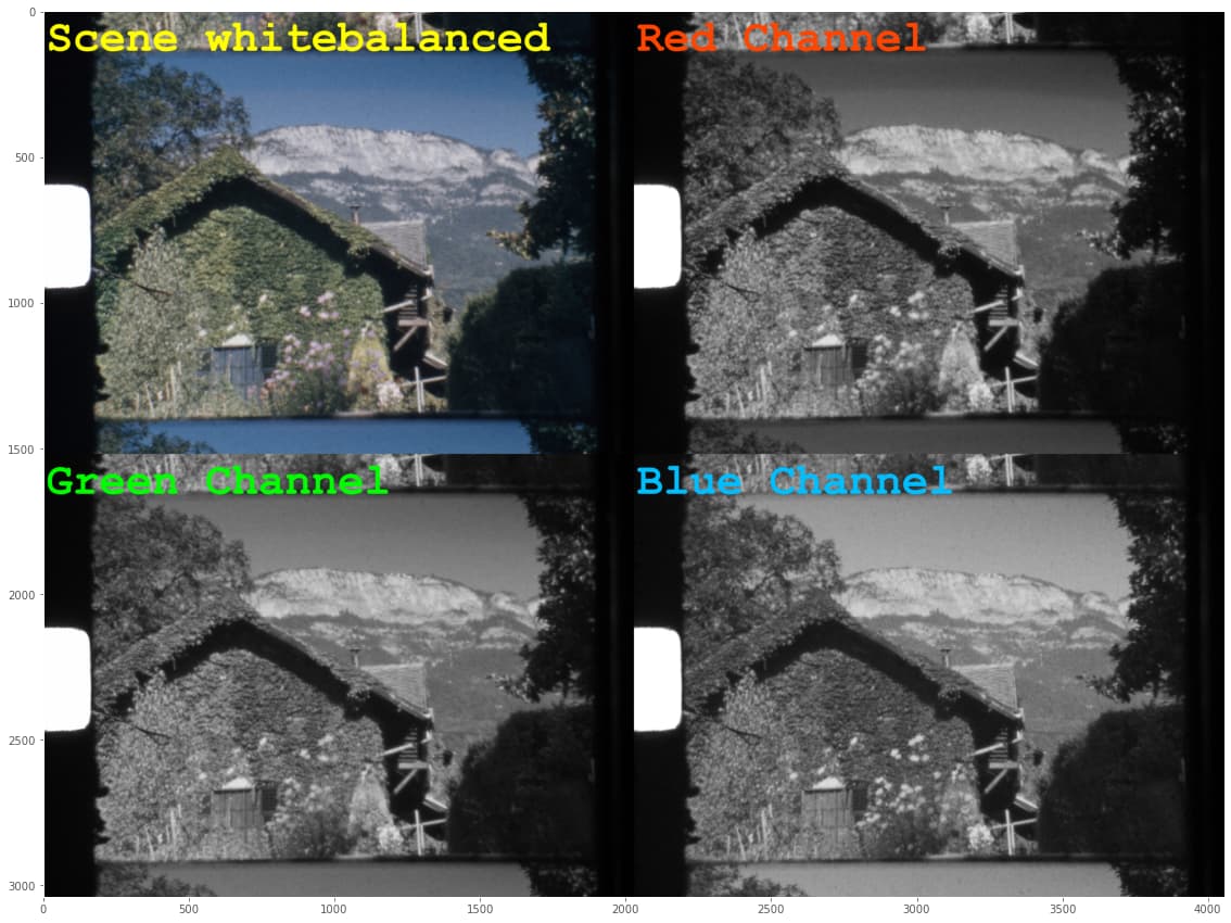
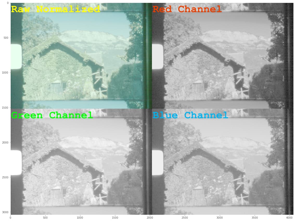
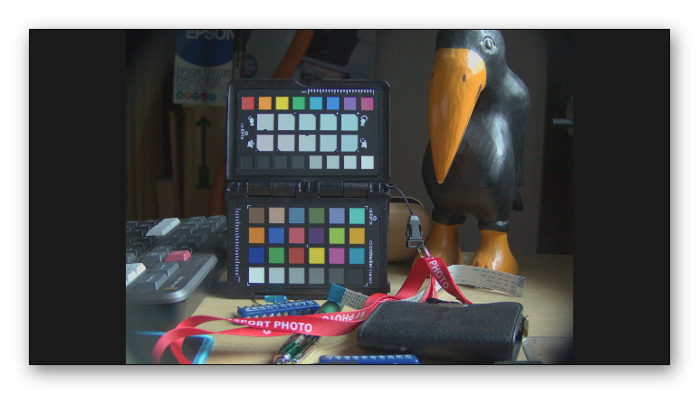
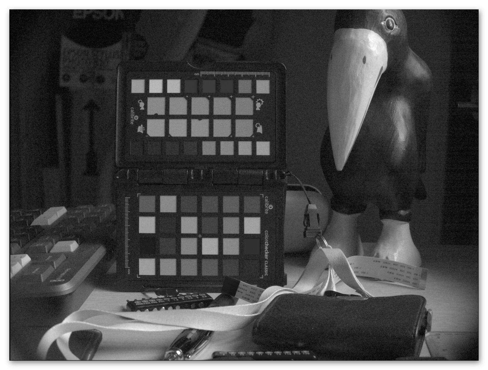
However, if you do not interfere manually at that stage, the whitebalancing values from the .dng-file will be taken. In my case, these values are fixed and set by my capture software on capture start. Applying the whitebalance, we end up with the following image:

In fact, not too much has changed from the previous image, as it is just a simple multiplication in the color channels. If anything, the banding in the red channel is slightly reduced. But the colors in the image alreay look better, but somehow not yet “right”.

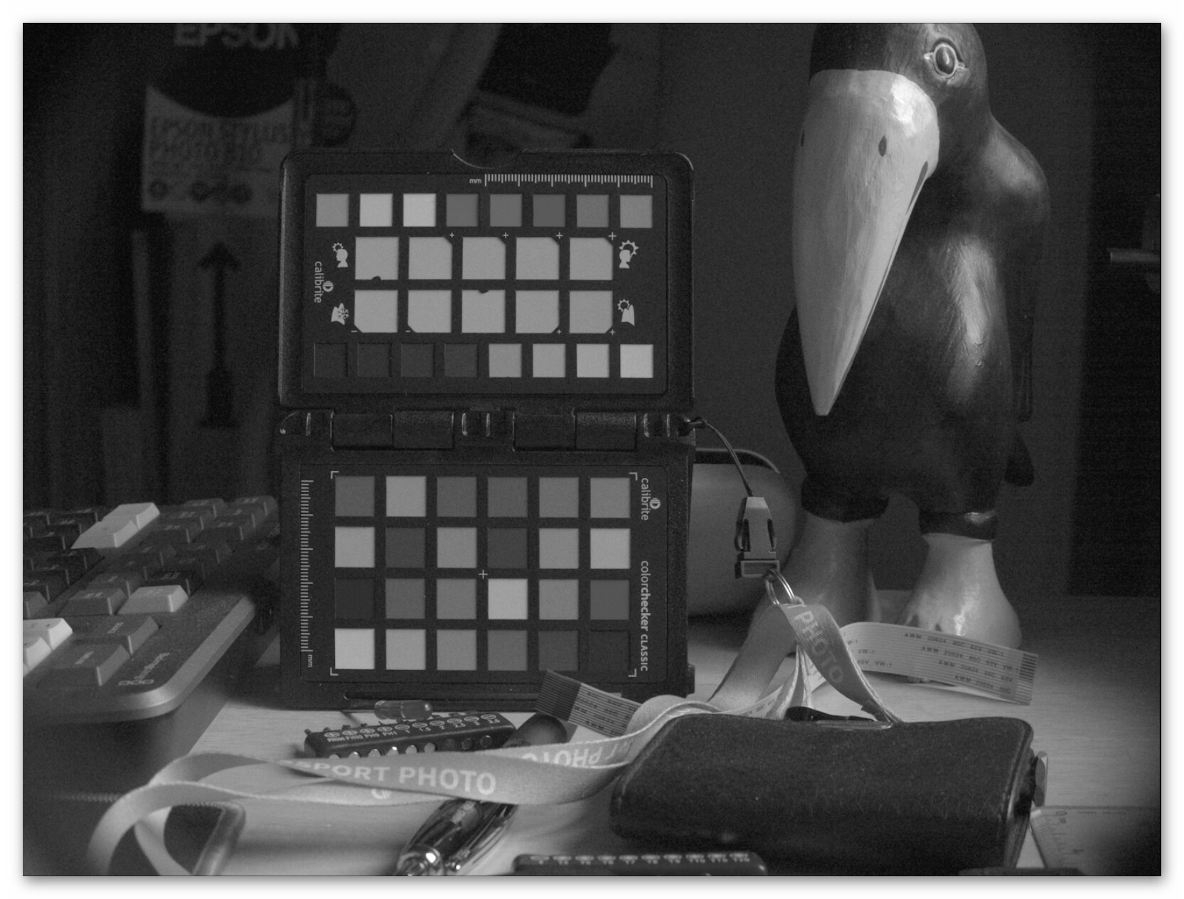
This is where the next step improves things. Here, a CCM (compromise color matrix) is applied to the image data. Like the whitebalancing coefficients, the CCM can come from a variety of places. For starters, there are usually two CCM embedded in the .dng-file. The picamera2-lib is here slightly special as it includes only one CCM in the .dng-file. If you do not prevent the raw converter from doing so, it will use this CCM matrix to arrive at the next step of development

Note that this CCM is actually again calculated by libcamera during capture time. So it will heavily depend on the tuning file you had been using at the time of the capture. As one can see, the banding in the red channel is more noticable. This is probably caused by the CCM mixing negative components from the green and blue channels into the red channel.

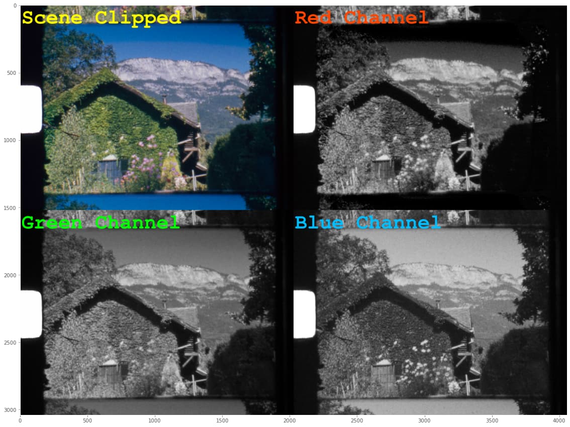
In fact, I cheated somewhat when processing and presenting the above images. All the calculations above were done in floating point numbers. And indeed, looking at the minimal values in the color channels, one discovers that they are negative - that is, not displayable on any screen. Clipping the above image to the displable range, we finally end up with this image

and here the banding in the sky is enhanced by the clipping process!

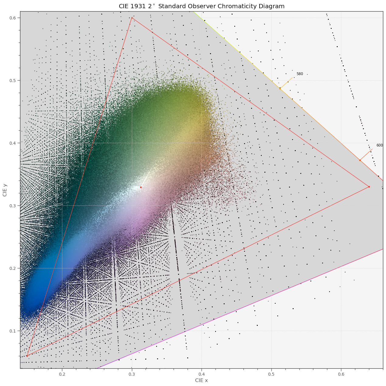
To give you another perspective, here’s the CIE diagram of the image tagged above as “Scene whitebalanced”:

The red triangle indicates limits of the rec709 color space. All pixels lying outside will be clipped, leading occationally to hard borders in the final image.

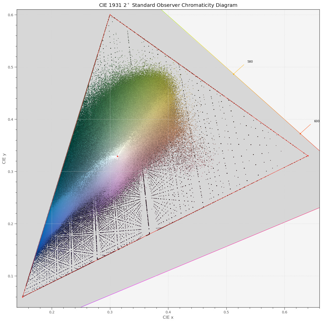
To make this explictly blunt, these are the pixel values of the image tagged “Scene clipped”, for comparison:

Clearly, rather large areas in the blues and greens are just gone.

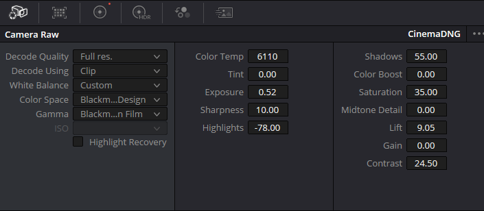
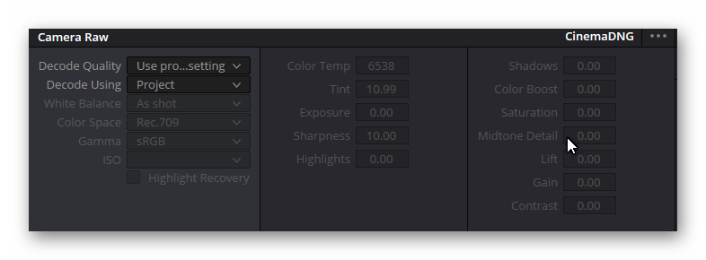
There are two ways to dealing with this: either manually tweaking the settings during the raw development, ignoring the data embedded in the .dng (as @npiegdon did above) or changing the color science of the HQ sensor to another, larger color space by default. (would it be really possible? What primaries would be the best? Would the RP5 log-like raw encoding be usable? Or another log-color space?)

The option of tweaking the processing of the libcamera seems to be an interesting option for me, but I have not yet looked into this in greater detail.

3 Likes

Since my reply a couple weeks ago, I’m starting to question this base assumption. Out of the five screens within my arms reach right now, four of them can display the more-than-sRGB “W” in the red block at the top of this test page. This includes the phone in my pocket (which is the only one that passes some of the HDR tests, too).

Have we quietly reached past the end of sRGB? I know a decade ago I already saw “98% of sRGB” advertised on monitor boxes at the store. These days they’re climbing to the higher percentages of P3.

I know that Netflix now has a minimum requirement for content providers that the footage be delivered as “BT.2020 limited to P3-D65” (where “P3-D65” is just the standardized/renamed version of Apple’s “Display P3”. P3-D65 uses the same illuminant and gamma as sRGB. Contrast that with the older “DCI-P3” which was created for movie theaters and has an illuminant and gamma optimized for Xenon lamps… but everyone online seems to intermix the two terms freely, unfortunately.)

Now I’m starting to wonder if I can keep a wider gamut through my whole editing pipeline. If I can already see >sRGB on my devices today, why waste that headroom when I’m hoping my family will enjoy these transfers for the next ten years or so?

I don’t know if I’m ready to tackle an HDR pipeline–which seems like a lot more work and requires equipment I don’t have–but at least keeping the color here throughout without squashing it down to sRGB at the end seems pretty doable and would already have a positive impact on the kinds of scenes you’re encountering here.

well, yes. There are a bunch of other delivery formats available (P3, rec2020, …) and it will probably matter what Vimeo or YouTube or any of the streaming services will adapt in the future. Currently, I am using daVinci Wide Gamut for my editing, but other promising options are available as well in daVinci.

That is exactly my goal. What I am kind of discovering slowly, and what turns out to be actually the real topic of this thread - that is not so trivial as it seems.

Obviously, the best approach to capturing the full data of a film frame is to capture raw data. Since the dynamic depth of a typical Super-8 frame hovers around 12 EVs (stops), with some scenes reaching 13-14 stops, the dynamic depth of the HQ camera (around 12 stops in it’s best mode) is just ok. So for critical material, it would be even better to capture at least two raws from each frame, with appropriate exposure times. Personally, I proably won’t go along that route, as it increases scanning times too much for my taste.

However, raw image data needs to be “developed” in something viewable/useable. And as I start to discover these days, here’s where the devils are hiding.

Each raw converter will depend heavily on metadata which is included in the .dng-file to be developed. There are two issues with that.

First, the .dng-files created with picamera2 or any of the apps based on libcamera is slightly different from what you normally would expect. A normal .dng-file would feature two sets of two color matrices for two different color temperatures. Each set would be composed of a “color matrix” and a “forward matrix”. That is, you will find a total of four color matrices in a normal .dng-file. The dng’s produced by picamera2 feature only a single “color matrix”. Given, that is a perfectly fine setup, but I am not sure how good the different raw converters available are handling such a non-common case. (Newer Adobe specs even work with more color matrices, by the way).

My two main tools, daVinci Resolve and RawTherapee, handle this case ok in the default setting: they simply use the single embedd matrix for converting the greenish raw data into a more or less true to color image which you can base your color grade on.

Which brings me to my second issue in this regard: the matrix embedded in the .dng-file is actually the real color matrix libcamera/picamera2 came up with when taking the capture. For this, libcamera/picamera2 is using the information encoded in the camera’s tuning file, specifically the color matrices in the tuning file.

But: these color matrices project onto the rec709 color space! So, if you are not very careful, colors are going to be clipped and artefacts are going to be introduced into your footage. The reason is simple: the color gamut of the Super-8 frame is wider than rec709. Note that the color gamut of the HQ sensor is wider as rec709 as well. So a lot of the intense colors of Super-8 film stock is still available in the .dng-file. However, it will not be available any longer once your raw converter develops the raw.

Let me give you an example: using the default development settings of daVinci for example (In the “Camera Raw” tab the entry “Decode Using” is selected as “Camera metadata”) you end up with the visible banding, as described above. The reason is: the build-in raw converter of daVinci implictly assumes rec709 as goal - which introduces the banding. If you switch the daVinci raw converter to “Decode Using” → “Clip” and set the color space to “Black Magic Design”, the banding is gone. (there is another setting “P3 D60”, which also already improves the development of the raw data, but not so much, compared to the “Black Magic Design”-setting.)

Which brings me to the other topic discussed in this thread:

@PM490: I think I have isolated the issue here, kind of. It seems to be connected to my remark that the actual raw data in the test-.dng file shows values below the blackLevels reported in the metadata of the .dng-file. Specifically, this observation:

I think this operation enhances the low level noise. Here’s a display of the original raw data - without blackLevel-subtraction (pushing the low levels quite a bit):

and here the corresponding result after the blackLevel-subtraction:

The noise bands on the right of the image frame are slightly enhanced, I would say.

In closing, here’s what daVinci came up with the inital raw file posted above,

using the following import settings:

2 Likes

Could you share some Davinci screenshots? I import the DNGs as image sequence in DVR Studio 18.6 and don’t see the “Clip” setting. To me the project color settings are quite difficult to understand. What color science are you using, and what variation of REC709 output color space?

Well, I try. I first opened up daVinci with a new project. Than I dropped a .dng-file into the Mediapool. On the “Cut Page”, I dropped the .dng-file onto an empty track, which created a timeline. The settings in the color tab are like this:

Snap_Donnerstag, 18. April 2024_21h31m15s_005_

Note that the “color science” is “DaVinci YRGB”, not “DaVinci YRGB Color Managed”. See below…

The default raw converter settings can be found on the “color page” and will look like this:

Go to the “Decode Using” entry and click on it. A menu like this should appear

Select “Clip” here. Open up again a selection on the “Color Space” entry

and select “Blackmagic Design”. This will result in a rather dull looking image, like this

You can either use the “Color Boost” and “Saturation” entries on the “Camera Raw” page for adjusting the colors to your taste, or use the “Primaries - Color Wheels” on the single node present in the “Color Page” to set up a primary color correction. The later looks like this

in my project and delivers as output the following frame

It seems that if you read in this way the .dng-file into daVinci, issues as discussed in this thread (clipping of highly saturated colors) can be avoided.

daVinci is not really known for in-depth documentation. So I have no idea what the difference between the various rec709 settings available in daVinci really stands for. In essence, “rec709” in this context (color) is really only a subpart of the full spec, namely

  • the primaries (red, green, blue)
  • the whitepoint
  • a gamma curve

In this aspect, rec709 is practically identical to sRGB. Some variants of rec709 seem to work with a different gamma curve, which affects the saturation of colors.

Whether the above described way of reading .dng-files into daVinci Resolve is the correct way or even the best way - frankly, I do not know at the moment. I will need a few more tests and experiments to figure this out. It seems that selecting “DaVinci YRGB Color Managed” in the timeline’s “Color tab” delivers mostly the best colors with the least effort… (it defaults to “Color Space” equals rec 709, with “Gamma” equals sRGB on my system).

4 Likes

@cpixip Thanks Rolf, that really helps. I wasn’t looking at the Color page for the Clip setting. I’ve seen many, many tutorials of DVR Studio about color grading and it is really complicated. Will try to use your workflow and see if it works for me. Regards, Hans

1 Like

Here’s a page dealing with some basic concepts on color grading:

especially the difference between scene-referred and display-referred workflows. Also, there is a CIE-diagram in about the middle of the page comparing the extend of a few common color spaces.

1 Like

… continueing investigating the issue of clipping…

Here’s an old test .dng-file, taken with the HQ sensor, of a color-checker. Development in RawTherapee, with “Working Profile” = “ProPhoto”, developing (“Input Profile”) using the “Camera standard” yields the following result

One can immediately see severe clipping in the red (blueish tones) and blue color channels (orange tones); on a closer look, also in the green channel clipping is present (in the highly saturated carrying tape of the color checker). Also, if you even look closer, all color channels feature the increase of noise on the right side of the image noticed by @PM490.

So: the noise increase towards the right side of the image seems to be a “feature” of the sensor.

I think the clipping occurs because the color matrix embedded in the raw image is assuming sRGB/rec709 primaries. Because of this, highly saturated colors are mapped into negative RGB-values which can not be represented by 16bit unsigned data.

Indeed, using 32-bit floats for processing and displaying the full data range available, I get the following

The min/max values of the color channel are in the floating point processing pipeline:

red:   -0.513839387841 1.75631591844
green: -0.0966420351081 1.24296306889
blue:  -0.145675931974 1.41227455726

Clearly, way outside the [0.0:1.0] interval a 16 bit unsigned data could represent. The image displayed above is normalized from [-0.51:1.75] (the maximal range present) to [0.0:1.0].

So it seems that the HQ sensor can record color values far beyond what sRGB/rec 709 can represent. Let’s see how far we can get within DaVinci…

If I choose “DaVinci YRGB Color Managed” in the “Color” tab of a time line, specifically using the following settings,

I do get access to these negative values; I needed to adjust “Gain” = 0.77 and “Lift” = 0.04 in the color processing node of the “Color” page to bring the data into the display range and ended up with this result

For me, this looks quite ok, I’d say. An additional improvement can be achieved by activating the “Highlight Recovery” on the “Camera Raw” tab; one gets the following image

(Hint: the difference is only visible in the beak of the wooden bird).

The “Highlight Recovery” checkbox can be found in the “Camera Raw” tab of the “Color” page of DaVinci:

Clearly, the saturation of the RGB-image recovered that way in DaVinci is less than the RawTherapee result. But to my personal taste, I’d prefer the colors of DaVinci. Would be interesting to see how Lightroom or other raw converters handle the files mentioned in this thread. I certainly will not preprocess the raw images of the HQ camera in an external program, but will try to stay within DaVinci for all processing, if possible.

There’s still some (yet unresolved) issues with the color grading of old Super-8 stock:

  • Super-8 film worked only with two color temperatures: “Tungsten”, which was the basic color temperature available, and “daylight”, which was realized via a special filter which was swiveled into the optical path. Of course, the actual color temperature of the scene was probably not exactly equal to either setting (think of flourescent lamps). So the colors of the film can be expected to be occationally quite off of the true colors of the scene.
  • Longer Super-8 footage is composed of several 3 min/15 m rolls. I have noticed color differences between rolls displaying the same scene - probably caused by different processing during developement.
  • I have encountered many Super-8 films were different film types are cut together. While this basically went unnoticed in the old days, during projection of the footage in a darkened room, it shows up dramatically in our current digital world. Here’s an example

The dog (above) and the duck (below) clearly live in different color spaces.

4 Likes

… continue with notes on my experiments with DaVinci, as I think they might be of general interest (or: someone more knowledgeable on the subject chimes in to comment… - in this regard, perhaps the detailed manual v. 18, would be helpful, but almost 4000 pages…)

However. When I looked more closely at the DaVinci results described above, I noticed that certain patches, for example in the red channel, were rather noiseless. In particular, the cyan patch (the rightmost patch in the second line from the bottom) is virtually noiseless - in contrast to neighboring patches.

Here’s a full resolution red channel only image, with output color space set to rec.709 (Scene):

The fact that this patch behaves strangely is indeed to be expected, since the color of this patch is actually outside the Rec 709 output color space. (There are other patches too which are also noiseless - no clue currently what is happening there.)

Now, if we enlarge the output color space for example to Rec. 2020, we get the following result:

Note that overall, the noise in the red channel is reduced - but now present in the cyan patch! What strikes me most is the difference in the highly saturated carrying tape of the color checker. While the printing is barely noticable in the red rec709 channel, it shows up clearly in the red rec2020 channel image.

Here, for the record, the rec2020 setting in its full glory:

This is quite a lot of settings, and most of them change the processing of DaVinci. I think all settings below the checkbox “Enable Dolby Vision” are not relevant, but certainly the “Working luminance” setting “SDR 100” seems to be important. Selecting any other setting here leads to funny imagery on my non-HDR display.

I’ve tried other color settings but all the simpler ones don’t seem to work as intended. For starters, this here

Non-working setting 01

didn’t get me anywhere. “DaVinci YRGB” is not working, one needs to turn on “DaVinci YRGB Color Managed”. If you do so, this tab changes to something similar to the following

which does not work either. You absolutely need to uncheck the “Automatic color management” checkbox and select the “Custom” entry in the “Color processing mode” (it’s the last one). Even than, you’re not finished yet. Important is that the “Timeline color space” is set to “DaVinci WG/Intermediate” and, again, that the “Working Luminance” is set to “SDR 100”. Maybe time to RTFM…

3 Likes