Yet another 8/S8 scanner build!

Hi All,

I wanted to share the build I’ve been working on for the last few months - like many people I have a trove of 8mm family films in my possession, in my case mostly from the early 50’s to the late 70’s that I’ve been wanting to view/scan/preserve.


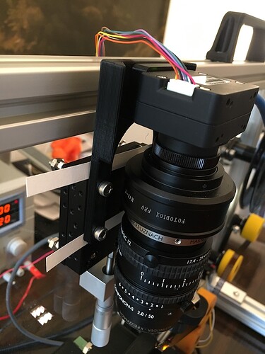
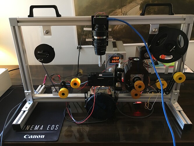
The scanner is built around a Point Grey Chameleon 3 camera with the 50mm Schneider Componon-S enlarger lens. Coarse focus is on the barrel, fine focus by way of the micrometer on the linear translation stage that carries the camera assembly. (Very glamorously shimmed with slices of index card and a voided check)

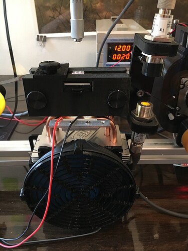
The gate is slightly curved (with a flat image plane area), my own design that I 3D printed. The diffuser is an opal diffuser from Edmund Optics and the light source is a high-CRI 3200K Yuji LED mounted on a CPU cooler. The scanner senses/counts frames by the sprocket holes using a 650nm laser/detector with a pinhole. I know there were issues with using visible wavelength lasers, but passing the “reflective” film through at an off angle has worked pretty well.

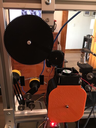
The film is drawn through the machine with a capstan run with a stepper motor. I went with intermittent motion out of an abundance of caution around using brighter light and shorter shutter speeds. I’d like to implement bracketed exposure down the road, so this path should reduce necessary redesign.

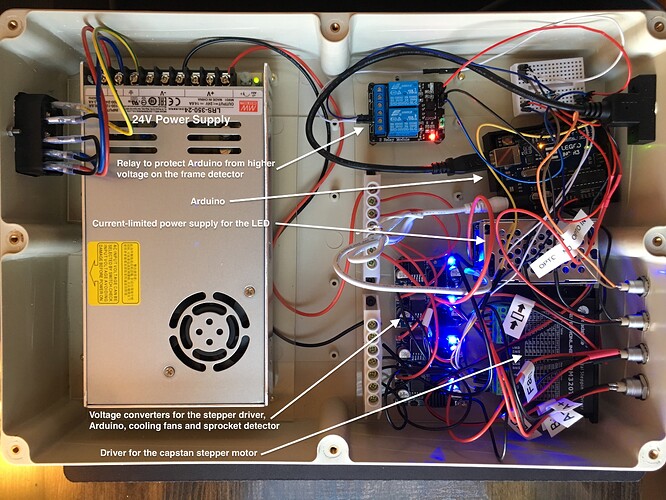
The take-up is run by a feedback loop with a limit switch a smaller stepper on an Arduino - a dancer arm (lower left in the picture above) pulls any slack in the film past the capstan (in the orange-backed enclosure) and the small stepper (middle) incrementally winds the reel (other side of the large gear) until it’s acceptably taut.

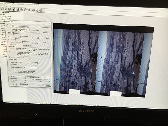
I’m using Point Grey’s FlyCap2 software to control the camera and acquire frames. The camera receives a trigger pulse from an Arduino (in the control box) that is dictated by the signal received from the sprocket detector circuit. In short, film moves → sprocket hole detected → film stops → trigger pulse is sent → delay → film moves. FlyCap2 has given me fine control over all the camera settings including the debayer method, but I’d like to explore custom software at some point (alas, far outside of my current wheelhouse).


And here’s a video of the scanner running, please excuse the hiss from my radiator (old NYC apartments…).

Youtube: 20190112 Scanner Update

And here’s some test footage from right before the holidays on an 8mm reel from 1957.

Youtube: Reel 40 Test

Overall the scanner is a pretty even split of off-the-shelf hardware from McMaster, 3D Printed parts and electronics from Amazon/other shops. The back plane is a piece of 1/2" Acrylic I had laser-cut. I’ve run about 1000 frames through at a given pass with good results, but I’m still working on some more tweaks before I turn it loose on a whole reel. I’ve been able to tweak the speed, and it’ll run as fast as 2 fps, but the sweet spot is really around 1 fps until I make more significant changes. The raw image from the scanner is stable to within ~1/6th the height of a sprocket hole, so I do a further stabilization pass in Davinci Resolve before any color correction. The future path should see a move to a dust-free enclosure and a dark, opaque mounting plane. Ideally with the option to swap out the gate and optics to accommodate 16mm film as well. That way I can scan all my work from back in film school - less urgency there though since Kodak’s Vision2/3 stock is not anywhere near as fragile as the 60-year-old Kodachrome from my Grandfather’s collection.

It’s very much a WIP right now, but I’m very happy to hear feedback and answer questions.
7 Likes

Very nice! It’s interesting that you used a Yuji LED. I’ve been testing them and haven’t heard of anyone else using them. I got some of their newer constant current 3200K and 5600K LEDs that they didn’t have published spec sheets for. Their preliminary information showed a great spectral response. They are the most expensive LEDs I’ve ever bought.

So far, I haven’t found a good way to concentrate and diffuse the light. Your Edmund diffuser looks interesting. I’m looking to get more light on the film by concentrating the light so I can use a shorter exposure and speed up the process. I’ve tried some LED lenses, but the light distribution at such a close distance was not good. I have had great luck with SORRA’s MR-16 constant current LEDs. They have nice spectral responses (not quite as good as Yuji’s) and have a builtin lens. Their LED with a 25 degree beam produces a very nice, bright, and even light at very close distances (less than 1 inch).

Camera wise, I’m on a similar track as you. I bought a FLIR (Point Grey) Blackfly S camera. I’ve done testing with FLIR’s Spinview software which I think is like the FlyCap software you used. I’m glad to see it’s working in an actual application.

I look forward to hearing more about your improvements.

Thanks! The Yuji LED’s showed a lot of promise from when I did the research for the illuminant part of the scanner last year - I was so busy trying to get it ready for the family “unveiling” that I sort of just stalled on further research. Also maybe because I thought I’d feel like a dummy if I found something way better right away after sinking $$$ in the Yuji’s, haha! I’m curious to see what else they’ve come out with in the meantime and now I’d love to look at Soraa and Yuji side-by-side with a chip chart.

I’m aiming to add condenser optics to the light path in version 2 - even with a comprehensive design in Fusion 360 and OnShape, I didn’t quite get how cramped the back plane would be, so version 2 should have more room where it all can spread out. The diffuser was a lucky guess, any less diffuse and I’d have a nasty hot spot in the image, any more and I’d start losing too much light. I just tried to position it as close as possible to the film plane without possibly being in focus.

Good call on the Blackfly S - I’ve been pretty happy with the Chameleon but in the past few weeks I’ve been considering putting an upgrade to one of the Blackfly S models on the roadmap, sooner rather than later. I think FLIR has been slowly pushing for a move over to the Spinnaker/SpinView, I should probably plan on doing that myself.

I spent several weeks figuring out all of the possible functions the Blackfly S supports. I was only able to figure it out by creating charts that I could use to log settings. As I would set up a chart to support one of the function tabs listed by Spinview, I would run into things that didn’t make sense or operated differently than expected. It took many iterations between looking at/trying a setting and studying the huge manual to figure out all of the interdependencies. If you are interested, I’d be glad to send you a copy of what I found.

BTW, the Blackfly is a very nice unit. I think I found a way to get it to control the motor on the projector I am using without using a micorcontroller. I’m starting with a projector for my 8mm stuff and believe I will need a Kinograph type solution for the 16mm film because they have shrunk over time and would not feed through a projector properly.

1 Like

This is a fantastic build! Congrats on a great approach. If you’re up for it, I’d love to come check it out in person (I’m in Brooklyn). Thanks for the thorough and well documented post. This is a great build.

Can you tell me more about the rollers you’re using? What material are they? Does the full frame come in contact with the rollers?

Also, I’d love to get a link to the LEDs you and @stevevid are talking about if you have them. Thanks again!

@stevevid That would be excellent! I know there’s little in the way of indicators within Spinview when the condition of one setting affects another, so without memorizing the manual it’s tough to know what setting combinations are “legal”.

@matthewepler Thanks! I’d be happy to show you the build - I live up in Harlem and commute to Sunset Park for work at a film equipment rental company. “Film” being an anachronism - we’re a totally digital house now. The LED’s in my build are these from Yuji - I went with the 3200K version.

After totally striking out on PTR rollers designed for projectors/scanners, I tested these from McMaster - they’re designed for conveyor belts, but they’re soft and have a similar feel to the PTR rollers. They’ve been very gentle on my film, but I settled with them because they were good enough - one of the many parts I’d probably change out if I knew there was a “correct” part to use. The full frame does contact the roller - to that point, my original design used sprockets to drive the film and I had some scary moments in testing where it was clear that some reels had some shrinkage and others didn’t, hence the soft sprocketless handling. I’m not sure of their efficacy in helping to remove particles from the film, but then again I haven’t cleaned any of the film much (aside from a light wipe) erring on the side of less handling is better, until I have a better method.

1 Like

Beautiful build- thanks for sharing. The stabilization you have in the sample reel is rather amazing. Would love to have more details on the post workflow.

@majumder Thanks! I tracked the corner of a sprocket hole to stabilize, but I noticed that there’s some subtle movement at the edges of the gate - perhaps a clue that the film had a registration issue in the camera originally, or maybe that’s just par for the course with 8mm of that vintage. The camera control software I use produces a set of debayered TIFF images that I import into Davinci Resolve. Resolve automatically treats the sequence as a clip, which I lay down into a timeline and then stabilize in the Fusion workspace. Generally a Tracker node (to track and apply tracking data) followed by a Transform node (to rotate) and then a Crop node is all that’s needed to produce a reasonable looking frame. After that I take a pass on the clip in the Color workspace and then it can be exported.

The trick with getting the tracker in Resolve to work well for the task of stabilizing the frame with this kind of motion was dialing in the mechanics/optics of sensing the sprocket hole. If Resolve has to search a large area for the tracking point(s) the odds that it will make a mistake go way up. I was getting footage that could be stabilized for a few frames, then it would jump around. The precision was very bad (almost unusable) with the full beam from my sprocket sensor, but I cleaned it up with a pinhole and it improved greatly, i.e. Resolve only had to look at a relatively small area for tracking. I suspect that reducing the size of the pinhole more will have the effect of further improving the stability of the image.

Amazing work.

Any chance you could share your 3D printed files, and possible any homebrewed code?

/Chris

@ChrisCph Thanks, I’m happy to share files, but they change on a fairly frequent basis and in some dimensions are customized to this particular build. In many ways, the scanner parts as they existed a few months ago are totally different from how they are now. One of the many goals for the build in 2019 is to reach a point where the major film-handling parts are finalized to the point where I feel comfortable having them machined from PTFE or Delrin. Similarly, I’m working on getting a PBS set up for the build so I can track and replace parts easier - it’d be much easier to share a design then when I can say “here are the files for roller and post 002-430-123-A” instead of, “here’s the file I printed last week, wait, yeah I think that’s the right one…”

@johnarthurkelly I can understand that you want things to be “ready for production”, before releasing them to the world. I’m trying to get a set-up going, similar to yours and the kinograph, but I’m new to the world of 3D modelling, and things are going really slow, and a lot hair being pulled (actually don’t have that much to pull).
The set-up is for large number (~100) of family Super-8 and 16mm film reels. For 3D models I don’t need “perfect”, just “working”, but I’ll continue with my own attempt at modelling, and if yours become available, I will definitely check them out.

Good luck with the project :slight_smile:

matthewepler - Sorry for the late reply. I’m tied up in many things at the moment. I hope to be back in my shop in a few days and I’ll get the LED info for you. I don’t remember the specific part numbers since I haven’t worked on the hardware since early November. I’ve been doing a lot of AviSynth and VirtualDub restoration work on some captures someone else did (very bad captures). I decided to go with constant current based LEDs so I can easily turn the LEDs on/off or adjust brightness with a control pin on a buck regulator from Spark Fun. I’m thinking of using a 4000K or higher temperature LED so the blues and green wavelengths are stronger to help offset the fact that the green and blue film dyes fade more than the red dye.

More later,
Steve

None of the images in this post seem to be showing. Is this a forum issue or broken links from the original poster?

@bassquake yeah it’s kind of strange - I’m the OP and they seem to have vanished.

@matthewepler have you seen this happen on the forum before? The images were up for at least a few weeks after the post went up. If there’s a way to re-upload them I’ve still got all the originals, if not I can drop them into a new comment on the thread.

Looks like we have an issue with the server. I’ll investigate. Thanks all for the heads up

@bassquake @johnarthurkelly images are back online sorry about that.

Thanks for letting us know!

@johnarthurkelly I’m loving this build!

I was wondering about the optical setup you are using. I can see you have the metal barrel version of the 50 mm Componon-S the “right way around” and I am assuming your camera is CS-Mount? What did you use to adapt the Componon-S to the camera? And what, for example, is the distance to the film’s image plane?

Wow. I know who I want in my tribe if there’s an apocalypse.

You’ve done a great job with this machine. I know it took a lot of research and experimentation. I have more of an entrepreneur’s mind rather than an engineer’s mind.

If you ever wanted to make some money from your efforts, you could sell a kit of this setup for others to build. You could also make enhancement or improvement kits for the RetroScan Universal machines. For instance, I think a lot of users of those machines would love some kind of PTR roller setup. Or some kind of film cleaning mechanism added on at some point before the transfer. I’ve always thought there were great opportunities to make accessories and add-ons for that machine. You would be the perfect one to engineer them, @johnarthurkelly!

For what it’s worth ----Todd Ruel

Thank you! Yes indeed, I have the “flipped” Componon-S 50mm mounted to a Schneider Iris and Helicoid focus adjustment. Those are mounted to a 5mm spacer tube (with M42 thread) and then an adapter to go from M42-to-C and then another adapter to go from C to CS. The distance from the film plane to the sensor is around 200mm - it varies somewhat based on how much of the sensor I’m filling with the film frame. Right now the film and sensor are 90 degrees off - I did this to expose a bit of the previous and next frames to help with stabilization early on. With some planned changes to the design the need for that rotation should go away and I’ll be able to use a larger portion of the sensor for the actual image.

2 Likes