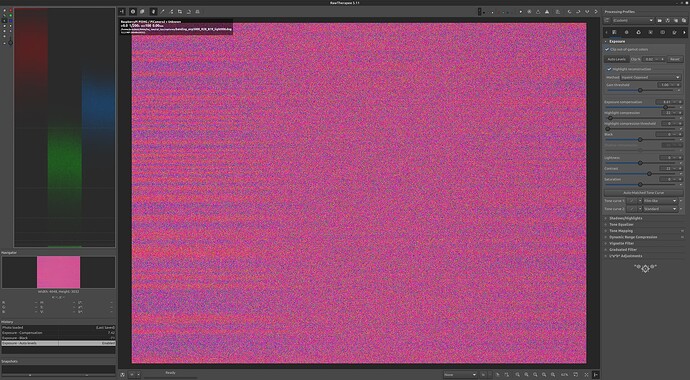
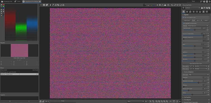
Strange encounter in the red channel/RPi HQ Camera

That is kind of interesting, considering that you replaced the stock IR-blockfilter on your system. And, accordingly, you are working with color gains redGain = 1.62 and blueGain = 1.9. While the blueGain is similar to what I and @verlakasalt are operating with, your ‘redGain’ is nearly half of the values we are using. That’s similar to my old setup where I replaced the IR-blockfilter as well. However, as mentioned earlier, I think the color science gets screwed by this.

In fact, I think at one point in time it is worthwhile to analyze this in detail, especially if we want to optimize for the case of severly under-exposed or badly faded film stock. But: that is a lot of work. One of the first things to check would be how good the performance of the combined light source plus modified IR-blockfilter would perform with respect to mapping the raw RGB values of the sensor into the XYZ-perceptual space describing human vision. The original IR-blockfilter performs here quite good. That is, it is recreating the human eyes sensitivity curves rather well. So color metamerism of our camera is quite similar to the metamerism we experience. This might not be the case with the changed IR-blockfilter.

The light source is also playing some role here. A whitelight LED with a high CRI is probably close enough to the spectrum assumed during camera calibration (D65 if I correctly remember), and such a light source samples the spectrum of the film dyes broad enough that everything should work out well. Not so sure about this if we switch to sampling the spectra only at the three rather discrete and narrowbanded positions in an illumination created by separate red, green and blue LEDs. I used such an setup at the time I was still using v1 or v2 RP sensors, and at that time it was not possible to capture raw data. So I at the moment, I have nothing to experiment upon. And rebuilding my RGB-LED setup (and/or replacement of the IR-blockfilter) would require quite some effort. Too much work for me at the moment - I am currently looking into ways to detect tiny movements which are happening during capture. There exists a perfect solution by @npiegdon, I even have the hardware for building one, but I want to look whether there are alternative approaches.

Reflecting again upon the noise stripes - I think they are caused by too high gains in the red and blue color channels. They are present in all color channels, even the green one, under certain circumstances, they are also noticable in normal imagery taken by the HQ sensor, they are content related - it seems to me that we are “seeing” here the working of an internal noise optimization in the HQ sensors imaging chip, the IMX477. In my approach, namely degraining as much as possible in order to recovering image information which is normally covered by the excessive film grain of S8-material, even retiming the 18/24 fps footage of S8 to 30 fps: the noise stripes are gone. Barely, but sufficiently gone. They are no issue at all within the context of the film footage I am processing.

In the context of keeping as much as possible the film grain visible, one could try to optimize the light source in order to lower the necessary red gain, maybe by using a lower temperature light source (more Tungsten like) - this should be handled well with the scientific tuning file. Or resort to capture multiple exposures (either with different exposure settings for highlights and shadows (@dgalland’s way) or multiple exposures with the same exposure speed (@npiegdon’s way) and combine them appropriately. Or optimize the exposure times/light sources to take full advantage of the HQ sensor’s dynamic range (@PM490’s way). For very heavily faded material, the idea of ​​developing a suitable color science is certainly out of the question anyway.

Yep, that could be one way to “improve” things. Fiddling around with the black level. In essence, these would put the noise back into the dark. However, difficult to do directly, for example in DaVinci.

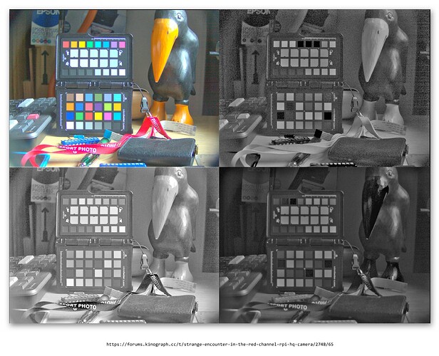
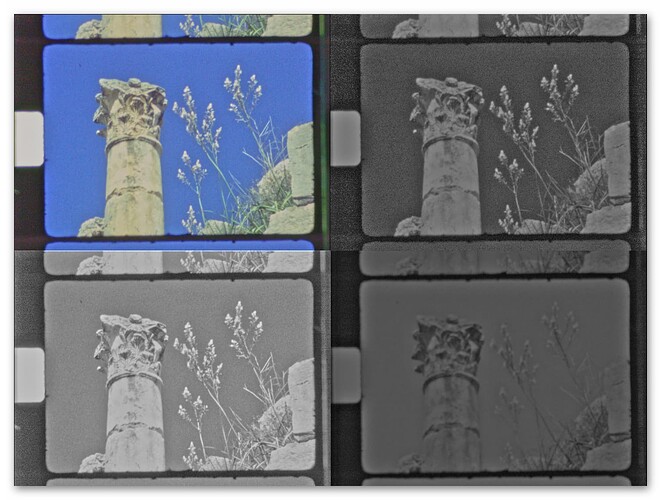
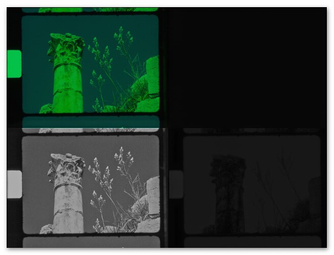
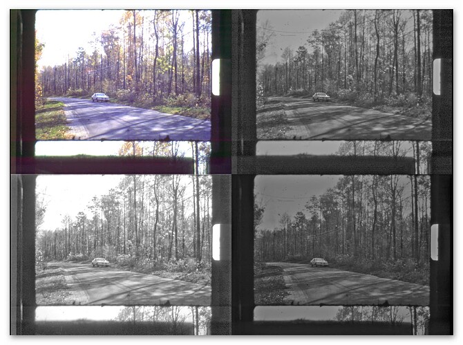
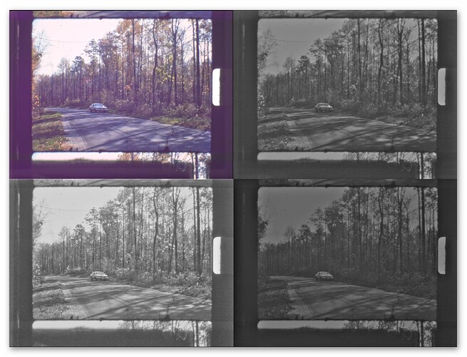
Update: I had a look at a few .dngs posted here. Comparing @verlakasalt’s “cob led”

with his “lepro led” (top left: RGB image, top right: red channel, bot left: green channel, bot right: blue channel):

one can notice that the later shows less of the noise stripes. Now, for both images the quoted exposure time is the same, namely 1/603. But the whitebalance coefficients are different:

cob led   - 0.3203177552 1 0.6680472977
lepro led - 0.4945598417 1 0.3575387036

which translates into the following color gains at the time of capture (red/green/blue gains):

cob led   -  3.12 1.0 1.5
lepro led -  2.02 1.0 2.7

So the red color gain of the lepro LED is less than the one used in the cop LED, and it seems that the noise stripes are less pronounced. This is a tiny hint that an appropriate light source with sufficient power in the red part of the spectrum could help in obtaining imagery with less noise stripes. Of course, one would really need to look into this in a more defined way to arrive at a real solution. Now the question is: where do I get 10x10 mm LEDs with a good Tungsten spectrum approximation?
2 Likes

After all that has been said in the previous posts, I am going to give my modest opinion.

I have always used a 12V DC powered lamp in my scanner. In fact, the lamp can be powered in a range between 10 and 18V, it has an internal stabilizer that ensures constant lighting.

I have never observed the problem of noise bands with the HQ sensor in my captures.

Recently, a user of my software notified me of the same problem of bands in the images. He was using a LED lamp powered with 240Vac.

When the lamp is powered with alternating current, the intensity of the lighting fluctuates between a minimum and a maximum at a frequency of 100 Hz (twice per cycle at a mains frequency of 50 Hz). With a rolling shutter camera we will have problems.

I recommended to this user to replace the lamp and use a DC powered lamp.

In fact, he notified me that the problem of bands had disappeared with the change of lamp.

Kind regards

2 Likes

Not bright enough for that fast of a exposure :grinning:
More like 1/50 in camera terms. But for well exposed film it would give more than 100% sprocket at 1/100 (exposure 10000).

@verlakasalt one other source of unusual “noise” is ambient light, particularly in the very dark areas of reversal film. At the time of capture, how was the ambient illumination?
This is less likely, but possible.

Do you mean that these images are using AWB to make the coefficients different?
I thought @verlakasalt was using fixed gains… that would be a simple test (turn the AWB off).

1 Like

No. Whatever the gains are at the time of capture (either set by the AWB or manually by the user), they end up as tag in the .dng. Only that they are the inverse of the gain coefficients picamera2 is using. I guess it was either AWB or him setting the gains manually. Does not matter to much in our context. At this point in time it’s just an observation: if two captures differ mainly by the amount of the color gains, the noisy stripes are reduced in the one with lower color gain.

While a quickly varying power source would make matters worse, I do not think that the noise stripes are caused by this. For starters, their characteristic behaviour, being noisy ( = random) and increasing from left to right would require a perfect sync between the CMOS-reading circuitry and the fluctuations of the power source. Hard to imagine how this could happen with different exposure settings. Also, these kind of stripes caused by low frequency power variations tend to be more regular than the noisy ones we discuss here. Finally, I know for sure that my illumination is constant over short as well as over longer times - but I do observe these noise stripes as well. At least in the moment I think it is related to not enough energy in the red band of the spectrum, requiring a quite large red color gain in turn.

Okay, I’ve hooked up the LED which I used before (which is cold white, so I have to amp red gain up even more), and it looks very much like the AC bulb is the culprit.

This is how the DC LED exposes:

And this is the AC bulb:

Not the best examples, but the few frames I’ve looked at seem consistent.

The AC bulb has kind of irregular, red/green alternating stripes, while the DC LED has kind of evenly distributed stripes of the same tint. I also set the bulb to equal gains red/blue, and it still looked the same.
:face_exhaling:

Update: I had a look at a few .dngs posted here. Comparing @verlakasalt’s “cob led”

… And now I’m properly confused. You’re absolutely right, it looks just as bad with the cob led in that dng. Occasionally I’ve seen horizontal lines depending on voltage with this lamp. But then they were gone again. I attributed it to the cheap power source…

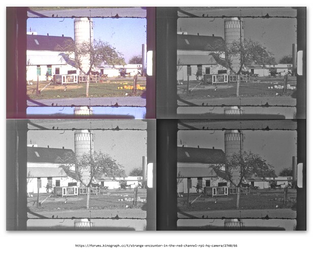
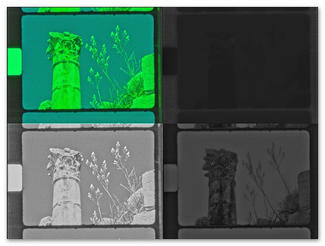
Well, the mystery deepens. I am still not convinced that the stripes are primarily caused by the difference between AC vs. DC or something like that. For starters, here’s an image captured only with rather constant sunlight illumination (again, as above, top left RGB image, top right red channel, bot left green channel, bot right blue channel):

That is - here’s no artifical, possibly varying illumination involved at all. However, on close examination, you will notice the characteristic horizontal noise stripes, increasing in noise intensity toward the right image edge. They are noticable even in the green channel. (As it is one of the example images I made the raw data available for download (test .dng-file) a long time ago,you can have an own look into this with your favorite raw developer.)

So even if you use the HQ sensor in a classical image setting, you get this type of noise.

By the way, the color gains of this image are very similar to the color gains obtained with your “cob led” setup:

 red/green/blue gains  -  3.12 1.0 1.56

So… - as these stripes seem to occur with ordinary daylight illumination, I do not think that we see here the effect of varying illumination intensity caused by the scanner’s illumination. I still suspect the applied color gains to play a role here.

To give some more arguments: for sure the light output of your illumination should stay as constant as possible. Otherwise you certainly will encounter funny stripes in your captured image.

But, the way whitelight LEDs are working, one would not expect to see too much variations between the color channels. That is, if intensity variations happen because, for example, your power supply is not up to the task, all three channels should show a similar brightness variation. That is, we should mainly expect an overall brightness variation.

However we are currently discussing colored stripes - that is, stripes were the channels exhibit different noise levels, independent from each other. At least with your “cob LED” vs “lepro LED”, the image captured with the lower red gain did show less noise stripes. That’s my current state of analysis.

Here’s by the way an old capture of you, displayed like the images above:


If I remember correctly, you once stated that this was captured with the HQ sensor. Note that there are barely any noise stripes visible. Can you recall the circumstances of this capture? It differs at least in exposure time with respect to your other pictures (1/50 vs. 1/600).

I don’t have much to add here–I’m not using the Pi HQ camera–but I can report that my global shutter sensor does not exhibit those stripes.

The RPi Global Shutter Camera’s resolution is right on the edge of being useful for our purposes, but it might make for an interesting additional data point…

1 Like

This might be a bigger hint than I’d like to admit. I’ve dismantled an old hähnel film viewer for the part that holds the film in place and the damned thing is silver of all colors. It didn’t seem to cause any issues, so I dismissed it, but what do I know…

I probably would’ve considered it earlier, but I was hesitant to remove the part from its current position. Guess it has to be done to reach everything, though. :face_with_diagonal_mouth:

I was able to create banding. The banding occurs when a color level is barely over the black clipping level of the algorithm. It was present in exposures from 1000 to 20000, as long as the light was adjusted to have a level (in this case red level) barely touching the black clipping. The banding is more visible with higher red gains, as @cpixip had indicated. The image below was with red gain at 2.8 and blue gain at 1.9.

I would speculate that what we have/see is noise partial clipping (bottom side), and speculate further that if there is any slight variation in the image black floor intensity, resulting in some black levels reaching the black clipping and some not, it would happen regardless of the light source. When the gain of red is increased, the noise amplitude is greater, and the effect is more visible. But the problem is apparent with all the channels -when their respective levels- reach the black clipping threshold.
In the case of @cpixip, that would be due to scene dark tones of natural light. But in the case of @verlakasalt, there may also be a variation of the illuminant which enhances the problem.

I need a bit more time to experiment… in the meantime thought that sharing the initial findings would align the collective thought process… an hopefully unconfuse us all.

2 Likes

I remember one Reddit post where someone had really bad banding in their Indoor photos using their DSLR “silent mode” (open mirror/shutter), and people attributed it to the frequency of the lighting combined with a rolling shutter, so having a global shutter might be beneficial.

But you probably already knew this (and the proper reason), while I’d have to refresh on the technical details. :slight_smile:

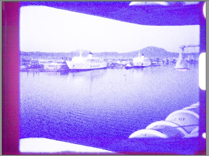
I’ve taken pictures with the lid on and it looks like this:

Red gain 2.75, blue gain 1.8, exposure 4000.

Looks much more uniform, so I’d wager the light source (or there being light in general) does have a play in this.

@PM490: The explanation of your findings goes a bit over my head, unfortunately. Aside from programinng, I don’t have any true expertise or education in any of the subjects useful for creating a film scanner. I’m just tinkering and trying my best at learning as I go. Do you have any resource that could help me better understand what’s going on, or maybe, like, an ELI5 version? :slight_smile: If it takes up too much time, please decline. I appreciate your (and all the other members’) contributions very much.

(night - Why is it that when the green channel clips, it turns into blue? - Photography Stack Exchange this was helpful, for starters)

I think you nailed it. Remember that I remarked above that the minimal intensity values in the raw data are lower than the blacklevel reported to the raw developer? Pretty certain that the hard cut-off in most raw developent software (usually, they are using uint16) acentuates the noisy data.

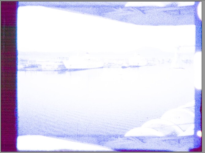
Lowering the intensity of my light source to get the sprocket hole at only 50% of the full intensity range, I get the following scan with redGain = 2.89 and blueGain = 2.1:

Here, I actually adjusted the Lift in the Camera Raw-tab of DaVinci to a value of Lift = 0.85 - I have the suspicion that this actually adjusts/compensates the blacklevel. This might be a way to improve situations where noise stripes are present.

(By the way - interesting that the image definition in the blue channel is so blurry with respect to the red and green channel. We have discussed this issue before - focus was set manually for maximal sharpness impression for this scan. EDIT: on closer examination - this unsharp image in the blue channel is actually caused by the original lens of the S8-camera! Image features like scratches are resolved fine by the Schneider Componon-S of the scanner in all three color channels!)

Now, here’s the result when setting both redGain = 1.0 and blueGain = 1.0:

First thing I noticed - rather similar noise stripes in all channels. Second thing: barely any image information in the red channel at all! In fact, the images I am showing here are processed in such a way to make the noise more visible. If I turn off that enhancement, you get the following image with color gains all equal to one:

Basically, there is no signal at all in the red channel!

So - how to improve this situation? That is, how do we reduce the amplitude of the noise stripes or get a better signal in the red channel?

Well, first of all, we should use a raw developer which does not work with uint16 and allows the adjustment of the black level to the material at hand. I suspect that DaVinci with its internal float32 processing fits this bill - one needs to check whether my suspicion that the Lift parameter in the Camera Raw-tab is actually working on the black level.

A second idea would be to use a whitelight source with more power in the red part of the spectrum. In other words, a warmer, Tungsten-light like light source. In fact, the scientific tuning file has entries for color matrices down to 2400 K - which features much more energy in the red band than a usual whitelight LED. Using such a “warmer” LED, the redGain necessary for a whitebalanced image would go down, reducing the noise stripes in this channel as well.

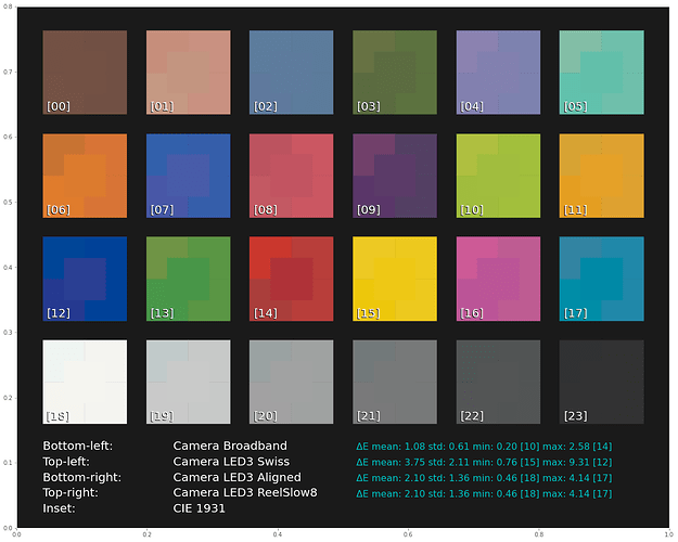
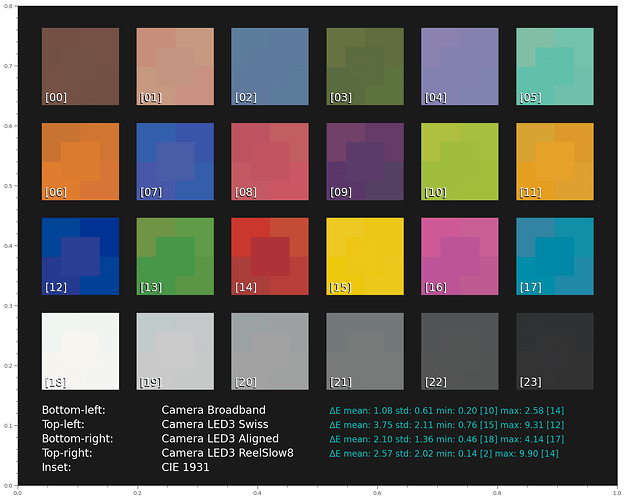
A third idea would be to go back to a set of three narrowband LED banks, one for red, one for green and one for blue. They can be individually adjusted to max out the dynamic range of the sensor’s color channels. I am a little hesitant with respect to this approach, as sampling with narrow LEDs is challenging with respect to color science. Here’s the reproduction of a color checker with different illuminations (from some old research of mine - the center of each patch gives the reference color, the patches around the center display the color with different illumination options):

The basic message here: while the color error of the HQ sensor with broadband illumination is quite good, namely 2.58, the narrowband illuminations do achieve at best 4.14 - which is not bad either, but not perfect.

@PM490: Now, I just realized that your own approach (sampling the different color channels sequentially with whitelight illumination and combining them afterwards) has a slight advantage over the narrowband illumination: you are sampling the frequency response of the film material over a broader range, compared to narrowband LED illumination. So this is in fact solution number four!

Of course, possibility number five is what @npiegdon is doing: averaging over several captures of the same frame in order to reduce noise in the shadows.

So… - a lot of possibilities. Which one is the more appropriate depends mainly on personal choices, I think. I for my part encounter no noise at all after my spatio-temporal denoising (used to get rid of the film grain). However, due to another project (detecting camera shake during capture) I might end up with capturing two or four raws of each frame anyway, so I might as well average these captures in the future. We will see. In case I find 10x10 mm LEDs with a warmer color temperature, I might be temped to swap them for my current whitelight LEDs (which operate at 6500 K) reducing the necessary red gain during capture. If I find some information about the frequency response of the dyes in common film stock (I have not yet found too much here), I might even pick up the narrowband LED setup again in the future.

1 Like

@verlakasalt no worries, we are all learning in different subjects. On the flipside, I am learning python on the fly to be able to complete my project.

Think of the noise as grass, with 3 color leaves. If one color receives more water, it results in taller leaves only for that color (gain = water, think of the red color). If the red leaves grow uniformly, the overall grass color would turn to red, but would still be a somewhat uniform color. What may be happening is that the red grass was clipped at a specific height from the ground (you have to imagine that magically one can cut only one color of grass while leaving the other two). But since not all leaves have the same length, only the taller ones are flattened by the cut, but those below the cut line remain with a random height. When the grass is watered then (amplified) the red leaves that were cut would show as a path (banding) which looks different than the ones that were not. Sorry if this analogy is not great… to make matter worst, the grass is actually cut from the bottom, not from the top.

This article may be helpful for you to follow the content of the dng. I do not understand 100% of the code, but having worked with analog cameras, somewhat understand the resulting steps on the signal/image.

The key here is that the sensor captures have an offset.

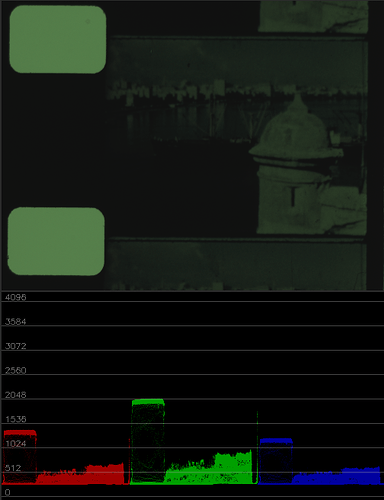
In the waveform above the lowest levels of each color are in the 250s. Note that the ones in the waveform above are a bit rawer than the raw, and a direct representation of what comes out of the sensor: integer linear values. The rawer values are cooked slightly into the raw dng, the cooking turn these into logarithmic (gamma adjusted) float numbers.

To be able to process the raw image, the first step (see the article) is “Subtract the black level from raw data.”… that’s your grass clipping. Prior to, in the information extracted it reads “black levels: [512, 512, 512, 512]”.

This subtraction is necessary to bring to near zero the sensor lower values, which are sort of a very dark gray (250s) instead of the expected black (zero).

The hypothesis here is that as the noise of one color is amplified differently than other, in the red channel strange encounter, the subtraction clips part of the noise, taking the random appearance, and making these visible as the banding.

These initial findings fully support @cpixip position that the banding source is the sensor/processing. Illumination variations make these more apparent, but are not the sole cause.

1 Like

This is where exposing each channel separately really shines. My sensor’s gain is always set to 1.0. Instead of empirically determining how long you can expose before any channel’s highlights are blown out, you figure that out for each channel. Then you could get as much signal as you like out of the red channel in this case, up to the limit of what’s actually there. (This way you don’t have to worry about tinkering with your light source, either.)

Is that an advantage? Aren’t you getting more crosstalk between the channels in the way the Diastor paper warns against? (I can’t seem to ever stop seeing the Heidi comparison on page 15.)

Here’s a little status report on this. The challenge: my scanner is made out of 3D-printed plastic parts, which is a bad choice for optical setups. This stuff is way too wobbly to be really of any use. Furthermore, as @npiegdon discovered, even a sturdier setup will show tiny movements when anywhere in the house somebody moves or closes a door. At least if your scanner isn’t mounted on a sturdy concrete slab…

@npiegdon detects such movement with a nicely constructed sensor and simply retakes an image if movement is detected. While I even have the parts of building @npiegdon’s sensor, I was wondering whether one could utilize the camera as a sensor.

Having no movement between captures of the same frame is also essential if one wants to average away any of the sensor noise, as discussed above.

So, the idea is simple. Instead of taking a single capture, several ones (in my case currently: only two) are taken in rapid succession. In full res mode, the HQ sensor is running with 10 fps, taking two captures per frame reduces this to 5 fps only. That’s the disadvantage with respect to this approach - but if we want to average anyway over a set of frames, that is the price we have to pay anyway.

So, the approach is the following. Immediately after capturing a frame, I capture a second one. Similar to this code:

    def grabFrame(self):
        request       = self.capture_request()
        self.frame    = request.make_array('main')
        self.raw      = request.make_buffer("raw")
        self.metadata = request.get_metadata()

        # grab a second frame
        request.release()
        request       = self.capture_request()
        self.frameB   = request.make_array('main')
        request.release()

        return self.frame, self.metadata

Before sending the raw toward the PC-client, the following operation is performed:

 frame = cv2.absdiff(camera.frame,camera.frameB)
 delta = np.average(frame)

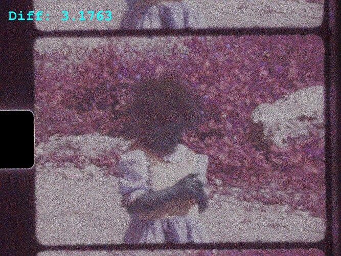
Here’s the “normal” result with no movement in the house


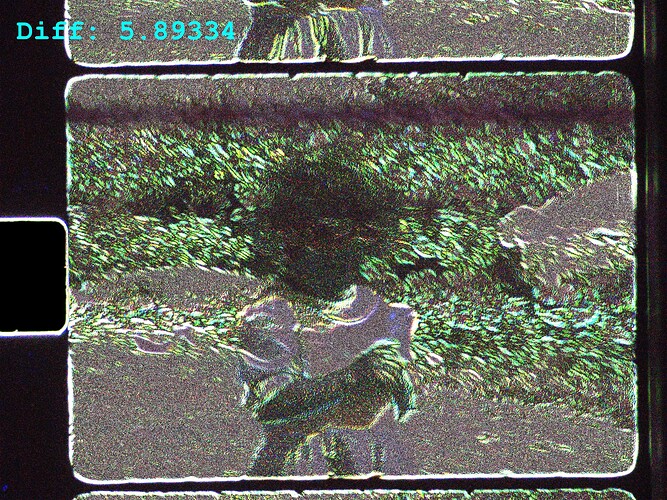
and here’s someone walking around in the room with the scanner:

Clearly, there are horizontal bands of large movements between the frame and the reference frame. These bands are mainly horizontal due to the rather low frequency of the movements with respect to the scan frequency of rolling shutter sensor. Speaking of this - a global shutter sensor won’t save you here; the movement will still be there, only in a global way - that is, the complete frame will be misaligned.

Such a capture should not be used for averaging - you will loose resolution if you do so. Luckily, even my simple np.average seems to be a not too bad indicator. There might be other measures which perform better - still a subject to be researched.

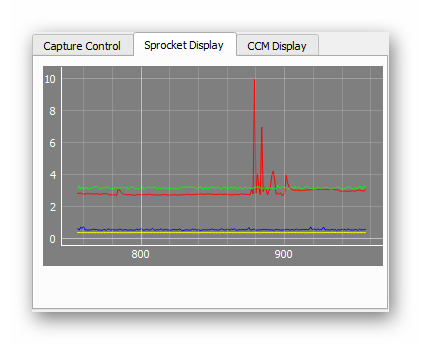
For illustration purposes, here’s a display of the actual scan operation over time (frame number). The green line indicates the time between captures (here slightly above 3 secs), the blue line shows the tension measured at the supply wheel, the yellow line tension on the take-up wheel. Lastly, the red line shows the differences between the consectutive captures of the same frame. From frame 880 to about 900, I was walking around the room:

grafik

(I would set the threshold to throw away and redo a capture with the described approach at a value of 4.0 currently. There is however a slight dependence of the error value with respect to the image content (note the slightly higher average value after frame 900). Maybe something more intelligent than the np.average used should be employed. We will see.)

So, at least with my scanner and house, it is essential to monitor the differences caused by scanner movements between frames which are intended to be averaged in order to improve the noise characteristics. It might be possible by just analysing the images from the sensor, without additional hardware.

2 Likes

But how do you do your color science? You probably have no idea what the camera’s manufacturer calibrated the camera for what type of illumination.

In any case, you need to do a lot of work in postproduction. Once you have achieved that grey areas are really gray in your final grade, are your skin tones really skin tones? Maximizing each color channel to utilize the largest range possible is as an ansatz totally ok, but only half of the equation…

This paper is bad. This has been discussed repeatibly here in the forum. What your camera sees with narrowband LEDs depends a lot on which wavelengths the LEDs used are centered. Years ago, with narrowband LEDs, my scanner picked up the contours of the daylight filter employed by a certain S8-camera. This was neither visible in the projected footage, nor in the scans after I switched to broadband illumination.

There is another reason why every color sensor used in any DSLR has a broad overlap between it’s color channels. Only in this way you can recreate the way humans are perceiving a given scene.

Think about two objects with different absorption spectra. Chances are that under sunlight illumination, these two object would appear having the same color - even so their spectra might be quite different. This is called metamerism - and to achieve this, modern camera sensors need broadly tuned filter curves. Otherwise, similar colors of a scene will end up looking quite different in a photograph of a scene.

There exists another type of camera where actually the color channels are separated as much as possible - multispectral cameras. Recently, they have been used for scanning film as well - but I have not yet looked into the results obtained. Not sure how they are actually condensing the multispectral data into the three RGB channels - need to do some reading here…

Anyway, these type of cameras are actually used in cases where a human observer would fail to notice differences in color. But multispectral cameras do. Think for example sorting out good fruit versus rotten fruit - you can do this kind of trick if you work with very narrow filter channels easily. The narrow filter channels enable the camera to see the differences, while a human observer doesn’t. Rather similar to the case I described above with the contours of the daylight filter suddenly unexpectingly appearing (to tell the truth: they disappeared/were less noticable after I swapped the red LED with one with another wavelenght. Even better results were however obtained after I migrated to whitelight LEDs.)

Now, if your source footage has degraded so much that any decent color science is anyway out of the question, you could indeed opt for best signal separation between the color channels. But with whatever colors you come up with in the end: they are at best just good (nice looking) guesses - nothing more.

My use case is quite different. The majority of my footage is Kodachrome, which does not tend to exhibit much fading. So chances are that the colors of my setup are quite similar to the colors a human would see during projection. That was the whole purpose of coming up with the scientific tuning file for the HQ sensor. Ideally, my illumination should be close to a black body radiator of a certain color temperature - because that was the illumination I had choosen when calculating the color matrices stored in the tuning file. Instead of this ideal illumination, I am currently working with a whitelight LED with a high CRI - which is close enough for my purposes (I hope). Using a whitelight LED with a lower color temperature could improve things in the red channel, but would make things harder in the blue channel. Whether that is worth the effort: I do not know. My scans do not show excessive noise stripes as discussed above.

Something is odd.

Even with a 5000K led, there should be plenty of energy in the red channel, particularly on the sprocket. So certainly the red channel -at the sensor- output has a sprocket.
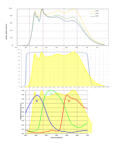
These charts represent my setup.

Setting the white light to quantify approximately 50% of the raw output range (linear) at the sprocket, the raw output of red and blue is similar.

The waveform results appear consistent with the resulting product of the LED spectrum and bayer filter sensor bands relative response.

The zero red channel level in your post -I believe- is at the DNG, and the result of the color science (I actually see a negative red in the first take).

In the experiments above, the sensor gain is 1 (since it is a capture of the raw array, not the processed-raw of the dng), and the exposure is the same.

Same here. Except that when working with greatly underexposed films, or shot with mismatched light temperature, or negative film, one the benefit of the separate channel is the ability to use the full range of each, at the expense of blowing up sprocket and other channel levels.

Depending on what one is pursuing, and the particulars of the material.
When working with RGB leds, the sensor relative response is replaced by the led bands. If a sensor had such narrow bands, it would not distinguish between slight color tone variations.
Yet it would -to quote the paper- look more vivid… for my taste, Heidi skin color is too vivid! More over, The browns on the image, like the leather jacket became tones of red, when in the white light version clearly have different shades of brown, and look of different color than the knit blanket.

This is a cool way to check for vibration!

With a monochrome industrial camera, I’m not sure how many layers of calibration I have to fight against. My impression was that–outside of dead pixel correction (which the API also gives me control over)–the raw 16-bit values I was getting back in my frame buffers are straight from the ADC (with a gain of 1.0) and the response I’m getting is more or less identical to the curves shown on the Sony Pregius datasheet.

For color science, the profile I generated from the IT8 target can transform the linear light captures (with each channel’s exposure times set for maximum SnR) into something that looks indistinguishable from looking at the film directly through a loupe held up to sunlight.

Indeed, my Kodachrome footage requires virtually no change to look excellent. This is despite narrowband illumination and different exposure times for each channel. The calibration works great and there’s plenty of head- (and floor-)room to bring things up or down in the event that the original footage was shot under less than ideal conditions. If there are any metamerism problems happening, they’re not apparent.

There are no color tone variations. The color on this film is produced by exactly three dyes. If you can capture those three, you’re done.

A “real life” situation (say, a still life with fruit and flowers) will have lots of variation across the entire visible spectrum. Narrowband illumination would absolutely miss most of those colors and would reproduce the scene terribly.

But film isn’t a real life situation anymore. It’s already been pressed down to three colors. The spectral response is uniform across the whole range of expressible (linear) combinations. Our job (assuming faded material) is to capture those three colors with as much (linear) independence between them as possible.

If the material isn’t faded and you won’t be adjusting the colors, capture it however you like. Crosstalk doesn’t make any difference in that case. But if you have any of that “almost solid red” looking film, being able to resurrect the color requires being able to capture the other channels while getting as little of the red mixed in with it as possible. With wideband illumination you can’t prevent or control that mixing.

good point. Yes, displayed in the above post is the .dng-data developed by the DaVinci raw converter. So not the original raw data.

that is my reasoning as well.

1 Like

Well, with a monochrome camera, you do not have any color science at all - you need to come up with your own, which you obviously did by calibrating with a known color target. Great! (And that probably did involve quite some work).

When I was using a narrowband LED setup, I did not like the dependence of the result on the center frequencies of the LEDs used. Combined with the unavailablity of a Kodachrome or Agfachrome target in S8-format, I decided that would not be my way of scanning film (I remember faintly that you used a 35mm calibration image and mounted that at several positions to get your calibration.)

That is certainly an advantage of your approach. As I mentioned earlier, I tend to simply cut out offending footage which can not be recovered…

Well, it’s slightly more complicated. You have the spectrum of the illumination (was normally a Tungsten lamp in the old days of projection), this is folded with the absorption spectrum of the film’s dyes; neglecting the projection screen’s influence, the resulting spectrum is interpreted via the (broadband) dyes in your eyes into a single color perception (XYZ). Obviously, the space of all spectra is way larger than the three numbers each pixel is carrying - so there is a lot of redundancy here: a lot of different spectra must yield the same color perception.

Let me repost the following image which shows the result of a camera looking at a scene (it’s not totally equivalent with our situation). Here, the calculations were done with the full spectral data, and several different illuminations were tested. For each illumination, the best color matrix was calculated and used to arrive at the final color impression:

The centers of each patch show the true color, “Bottom-left” corner of each color patch shows the result with a broadband illumination. Of specific interest is the “Top-left” corner of each patch - these are indeed the colors obtained with the Swiss’s paper suggested narrowband illumination. The mean broadband error is 1.08 (a perfect result; everything below one unit is not noticable by human observers) with the maximal deviation on patch 14 (“red”). The narrowband Swiss illumination achieves (again, with separately optimized color matrix) only a mean error of 3.75, with the maximal deviation of 9.31 at patch 12 (“blue”). Given, without a direct reference like on this sheet, no observer will notice the difference. (That one can optimize even narrowband LED setup shows the “Bottom-right” corner patch - the maximal error reduces here to 4.14. The “Top-right” corner patch “Camera LED3 Reelslow8” shows the results with the listed LED-setup in the backlight thread .

Well, without sufficient calibration material, I opted for the approach to use a broadband lightsource close enough to the light source in a projector and optimized the color science of the sensor in such a way that with usual illumination (specifically black body radiation of a given color temperature) the colors which would end up as RGB-values are close to the expected ones.

You started with a calibration target - which is certainly a more precise way of doing color science. However, that calibration is in principle tied to a specific film stock. For another film stock, you’d would want to redo that calibration to keep that precision. I do think that due to the rather broad curves of normal film dyes, the calibration from one film stock should transfer also to other film stocks. Even in the case the signals are captured with narrowband sampling. In fact, that is what you are observing. I am certain that you did not calibrate with Kodachrome, but you claim to get good results. Great!