Yep, it was a pain for sure. I wish there were somewhere you could get 8mm IT8 targets (though the grain noise at that scale would hurt its overall usefulness)…
With as much color correction as I’m applying after the fact (even to the Kodachrome footage), it’s a bit of a moot point. The calibration gets everything into the right ballpark and I edit from there. Again, if there’s slight metamerism going on between the film stocks, it’s imperceptible to me.
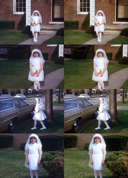
Here’s an example of nicely exposed Kodachrome with no fading that I’m still adjusting to taste for things like white balance. The left is straight off the scanner using the IT8 calibration. The right is closer to the final image I’d like my audience to see. (The original seemed a little too blue/cool.)
I’ve looked through your posts as well as the code you’ve linked and I think I still need a few pointers on what to look for exactly.
How did you determine the above values? Which values/levels do I need to observe in order to avoid clipping? At which point do I retrieve those values? From the dng? Or from the array before the dng? Can I find them among the data the linked code puts out? How do I put all this information to use?
Edit: To frame this a bit: What I understand is that I need to find a level of illumination/exposure that avoids values below a certain level (e.g. 250 within a 12bit range). Right now I only know how to create a histogram based on an 8-bit png (in Python). Since I’m only now grasping the meaning of “linear dng” - if my dng is linear (is it?), that would mean I couldn’t go below a value of about 16 in the black/dark areas when represented as an 8-bit image. But I’ve seen frames with “blacks” below an sRGB value of 3 to 0 without that particular type of noise banding. What? I’m constantly in a state of thinking that I’ve understood what’s going on but then I feel like I haven’t understood anything at all.
Edit2: I’ve seperated the channels for my 8-bit histogram and it appears that large areas of red-value below 5 within the image area result in the above case of noise banding. (A few speckles don’t seem to be relevant). I’m going to test further whether this is consistent for my setup. It probably changes when gain values change…
Set raw file to analyse ['I:\xp24_full.dng'] >

Image:  I:\xp24_full.dng

Camera Levels
_______________
             Black Level   :  256.0
             White Level   :  4095.0

Full Frame Data
_______________
             Minimum red   :  77.0
             Maximum red   :  4095.0

             Minimum green :  167.5
             Maximum green :  4095.0

             Minimum blue  :  162.0
             Maximum blue  :  4095.0

Center Data
_______________
             Minimum red   :  208.0
             Maximum red   :  1367.0

             Minimum green :  260.0
             Maximum green :  4057.5

             Minimum blue  :  230.0
             Maximum blue  :  2889.0
Now, the first two lines report the black- and whitelevel of the data. In this case 256 and 4095. These numbers are not fixed but depend mainly (in the case of the HQ sensor) on the type of RP you are using. A whitelevel of 4095 indicates that something smaller than a RP5 was used.
In any case: the light intensities the sensor saw are encoded in a linear fashion in the raw data. Absolute black corresponds to the reported blacklevel, the whitest white is corresponding to the reported whitelevel. You should never find pixel intensities larger than the whitelevel. With the blacklevel, that is a different story.
The actual minimal and maximal values found in your raw file are reported in the sections following. Indeed, the largest value found in the full frame data is listed in all three color channels as 4095, which is identical to the whitelevel reported. So there’s a good chance that there are some areas in the image which are burned out. And indeed, this is the case with this specific image.
Now, looking at the minimum values found, they all turn out to be lower than the blacklevel reported. What is happening here? Are these pixels blacker than black? In a way they are - but most probably just useless noise.
Looking at the following center third section (“Center Data”), the situation is slightly better. All bright pixels found are well below the maximum value (the reported whitelevel). The largest intensity is in the green channel, 4057 < 4095. Also, in the green channel, the darkest pixels stay above the blacklevel at least in the green channel - however, the red and blue channel are still lower than what would actually be expected. Again, that is a characteristic of the HQ sensor and the associated software and there is nothing one can do about - maybe treat these values as “super-black”? Your choice…
Well, in fact, there have been a total of 5 different approaches suggest to reduce these noise stripes found in the HQ sensor. And there is of course even a sixth: get a better sensor.
For further information on how the raw data is transformed into a viewable image, I would suggest to check again the script listed here on the forum which does a complete Python-based raw development. It contains all the secrets one wants to know.
There is more to it, as @cpixip already pointed out. The image is the leftover that the dyes didn’t eat.
The disagreement is what is the best leftover…
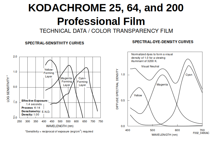
On one side, there is dye crosstalk that the film process inherently has and is undoubtedly reflected in reversal film datasheets, including Kodachrome. White LED cannot reduce it.
On the other side, RGB is unlike the sensitivity and color response of a color camera/sensor (HQ sensor depicted below in gray), yet allows for reduction of dye crosstalk.
Yes, both end in three values (additive colors RGB) that would become light in some form of display so we can see the image.
I beg to disagree that there is no difference with unfaded material, since the crosstalk is part of the color image the film was designed to render. But at the end it boils down to taste and resources.
Results of faded dyes with white light? here is an example previously posted. Note the scene was shot with a mixture of natural light (window) and tungsten reflector, so much color correction was needed.
On a side note, the DAC PCB in my scanner was built to add up to 7 additional LED drivers for narrow band LEDs, for a V2 of the scanner. But first I need to redesign the sphere PCB (or PCBs) to accommodate. In other words, I am in no way dismissing some use cases for narrow/multi spectrum LEDs, only my opinion is that it is not necessarily the default-best path. When (if I ever get the time) to put it together, get the White+Narrow illuminant together, it would be a way to confirm my hypothesis that WRB scanning process would have some benefits over RGB, and compare results of White vs RGB too.
Very cool results.
@verlakasalt When capturing the DNG make every effort to have the active image be slightly higher than black. When in resolve, use first Lift to adjust it back to a lower level of a darker or zero black.
@cpixip in Resolve, because of the raw-raw-tiff, I am setting the timeline to linear to match the source files. In that context lift and offset work a bit different, and offset appears to be a straight subtraction of the channel offset. When not in linear, these two appear to do something similar, probably due to the gamma curve already in the dng.
While we were having this discussion a few days ago, I was searching around for some info and bumped into a post on some other forum that mentioned an alternative supplier of IT8 targets that I’d never heard of before: greywhitebalancecolourcard.co.uk.
They make 35mm Ektachrome slides of an IT8 target with the accompanying data files for a price similar to Wolf’s. (Their worldwide shipping is also quite reasonable!)
I knew it was a long shot–I’d already tried contacting Wolf about this in the past and never received a reply–but I used their contact form to ask whether they could produce a custom version of the 35mm slide where the calibration target was printed smaller in the center, say at 16mm or 8mm size. I admitted that at those sizes you’d be fighting an uphill battle for accuracy against the noise in the grain, but that I’d still be interested anyway.
Four days later and I just got a reply: “I can do this but it might take around 10 working days. Is that okay?”
This would reduce the burden of calibrating a sensor from hours of carefully repositioning a target to just the time it takes to get a single nice capture (and type one Argyll command line)!
I haven’t replied yet. I was wondering if I should mention that–if possible–they should make a few extra in the smaller size because I know some other people that might also be interested in the same thing? Would anyone else be interested? Or should I be the test subject first to see how useful it turns out and report my findings here?
My know how on developing a color profile or using Argyll is zero. I would certainly be interested in something to test/calibrate the experimental methods.
Something more practical -at least for me- would be a target that can use the color match feature of Davinci resolve.
My thinking is scan in whatever method one prefers for the source circumstances, even in raw-raw (raw values without color science info), even linear values, and let resolve do the calibration.
To that effect, I was considering creating a simulated target frame capture. Basically, to normalize the capturing process, create a TIFF with what an ideal color target values would be at the sensor (keep in mind that in my case there is offset and more green).
While it will not be color accurate, nor will it calibrate the light, it will set Resolve color correction pipeline in correctly for -at the minimum- offset, gamma, and gain, and then one can do the lesser adjustments for light/color balance, which one would do anyway for visual appeal.
The automatic function of Resolve expects all colors to be on the same range. When binning with all channels captured at once with the same light, it does not compensate for the double green (the tint is off to green). When each channel is captured for maximum range, the function works flawlessly.
Well, a nice discovery. However, as you remarked already by yourself,
And it’s not only the color corrections, we could throw into this the fixed color temperature of the film material, unmatched to the light actually contained in a scene, or the varying characteristics of the different film stock at hand, or even variations during the development of different 15 m film rolls (I have one Kodachrome example showing this bluntly). Not to mention different fading characteristics of film stock, heavily dependent on time and storage conditions.
So any color processing will probably at best end up with a viewable image, but certainly not the “right” colors.
Nevertheless, of course anybody wants to be as close as possible to “true” colors for the final version of a scanned movie. That is, the scanning camera/illumination combination should be as true as possible. If you do not have a camera with color science to start with - like in your case with a monochrome camera paired with narrowband LEDs, a calibration target with the appropriate software surely makes sense.
The normal use case would be a camera combined with a broadband illumination, not too far off from a normal white light spectrum. Here you’d expect that the camera manufacturers color science is doing a decent job in capturing the colors of your film. I am not so certain if the camera in question is a machine vision camera, I am certain that the manufacturers default color science for the HQ sensor is off a bit - that was the reason I came up with the scientific tuning file.
The later was actually created without any reference or calibration image ever taken. The approach was to simulate the complete optical pathway in software, based on the known filter responses and illumination spectra in question. Imagery with color checkers were only used after the color science was computed to check the performance. This is also one preferred way according to ACES-documents. If (and that’s a big “if”) the spectral curves are available, there is no need to use calibration targets - which have their own challenges. You can directly calculate the appropriate color science. This worked well with the HQ sensor, a little bit less well for RP’s global shutter camera, and I have not tried more than this at the moment.
In the end, the differences in the approaches will probably be overshadowed anyway by the variations encountered in the source material.
Check the “TIFF and reference data” link over in this post in the Backlight thread. The “argyll steps.txt” file has everything you need. One command to read/compare your scan of the calibration target with the calibration data supplied by the manufacturer. Then, another command to generate an ICC profile from it.
With an ICC profile in hand you can do lots of things. It’s usable directly in places like Photoshop where you can simply “assign” the image to use that profile. But it can also be used to generate the kind of LUT that Resolve likes. So your first node would be to use that LUT and you’d be starting with the nice, “real” calibrated results for all your footage.
That thing is wild! Anytime you add “NIST-traceable” to a product description, the price gets another zero or two. But having 98 spectral response data points at 5nm increments for each color patch is awesome. I don’t know what I’d do with it… but it’s awesome.
I’ve noticed the same throughline across all my hobbies: metrology. For whatever reason, I seem to love precise measurements and quantifying anything I can get my hands on.
There’s something to be said here for why we calibrate monitors, scanners, and printers in the first place. Each one is a little different. And they drift over time. I generally distrust every “out of the box” state my devices arrive in. (This probably dovetails into my statement about metrology just now. I can’t turn it off in my brain! )
Agreed.
Alright, I’ll point the greywhitebalancecolourcard people at this thread and mention that there’s at least a little interest in them maybe making more than one at the smaller size.
Having already mentioned ACES, I am going to play a little bit “devil’s advocate” here…
I am pretty sure that this thread on the ACES-forum touches the original question - namely negative intensity values due to out-of-gamut colors*. There are even some comments/suggestions in the linked thread which directly discuss insufficient blacklevel handling similar to what was already discussed here in this thread (suggesting to mis-use the “Lift” parameter of the “Raw Camera” tab to solve it).
With respect to input profiles and LUTs, I’d suggest to view this video by Daniele Siragusano, referenced in the cited ACES-thread as well, about additive mixture challenges and why they are important (skip to 07:20 if you are in a hurry). In short, you probably want to avoid non-linear operations in your input profile (that is: non-linear operations performing gamut adaptions. LUTs are usually non-linear mappings). Those things should probably come later, in the color grading step? (This video is talking about cameras looking at a real scene (light mixes linear in a scene and in the camera) - however, our scanner cameras are looking at a film positive. Which is basically a non-linear media from the start. This might require a bit of extra thinking.)
(* these negative “out-of-gamut” colors are not really a “curse” if your image processing pipeline can handle arbitray negative and positive values, like in DaVinci with it’s 32bit floating point format. But other software might clip negative values to zero and large positive values to whatever the maximum is - in the case of 8 bit data it would be 255, in the case of 12 bit data 4095 and with 16 bit data, that would be 65535.)
(EDIT: funny that we discussed some of these things nearly 6 years ago. There has been some progress I think - we all agree that all approaches will yield a basic scan from where the artistic interpretation towards the final product can start (that is, “color grading”).)
@cpixip You mentioned using a 10mm x 10mm form factor. I was searching in the forum but only found the reference to the LED. Do you have mechanical drawing/spec of the LED PCB?
Brainstorming about the next round of LED PCBs, and once I figure out what the light for my V2 design would look like, would like to also make use the same PCB order to make some 10mm x 10mm form factor for the white bridgelux and facilitate a lower cost for 98CRI LEDs for scanning.
EDIT: Reason? my PCB was built for the projector modification, and made it work for the sphere. Have everything in Kicad already, so making a 10x10 along with other PCBs will not be trouble.
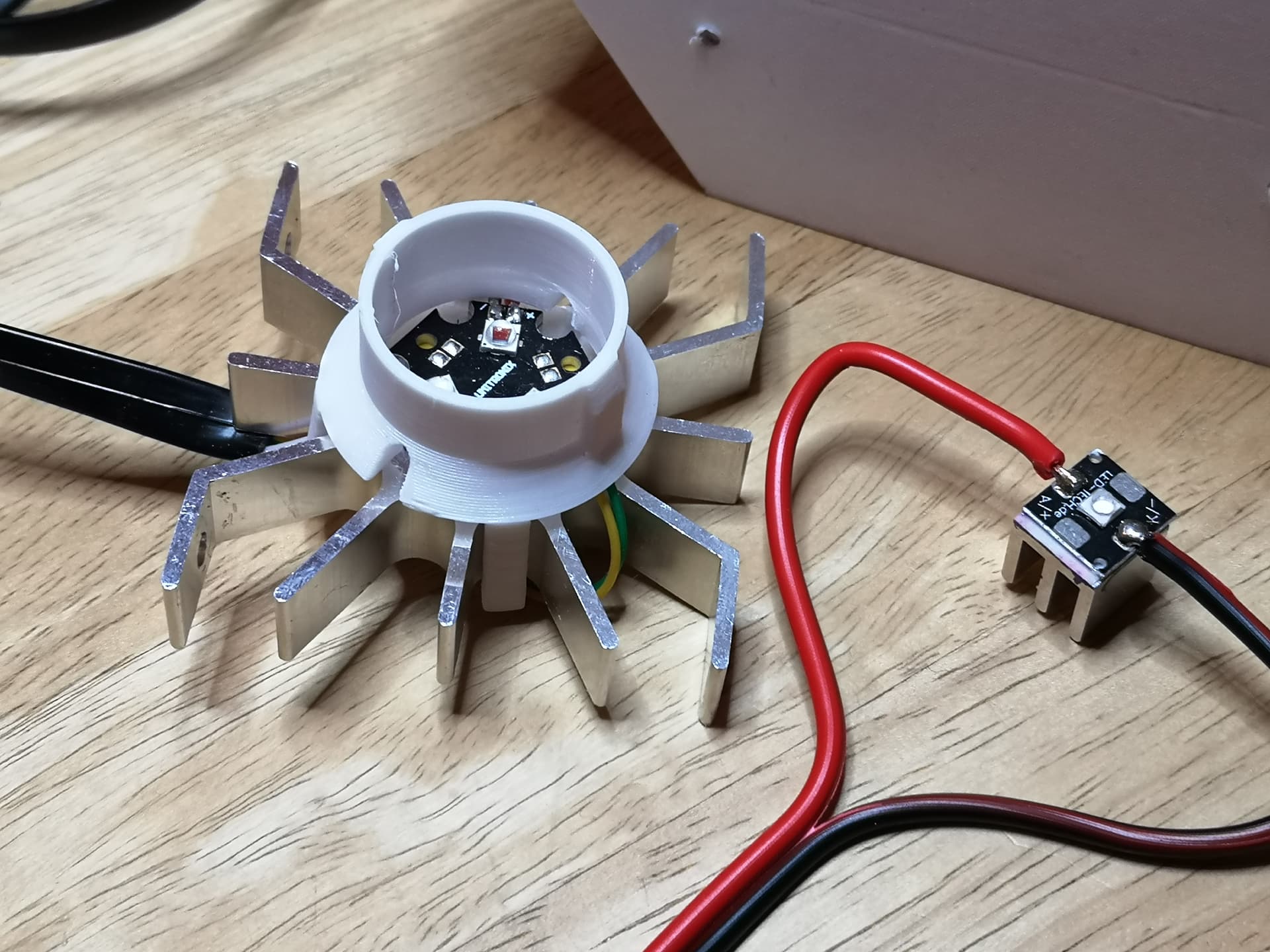
The right one shows the LEDs I am currently using. It’s simply a 10x10 mm PCB with a heat sink attached. At some time, this was one of the standard mounting options of those tiny LEDs
These LEDs are paired with my 3D-printed integrating sphere, described here (including .stl-files). I am considering upgrading the LED illumination, but for this, I have to take apart the whole film scanner.
And: before I start this project, I first want to understand the colorimetry (color science) of various illumination setups - research done years ago and which somehow went out of focus over time. One result of these previous simulations was this here
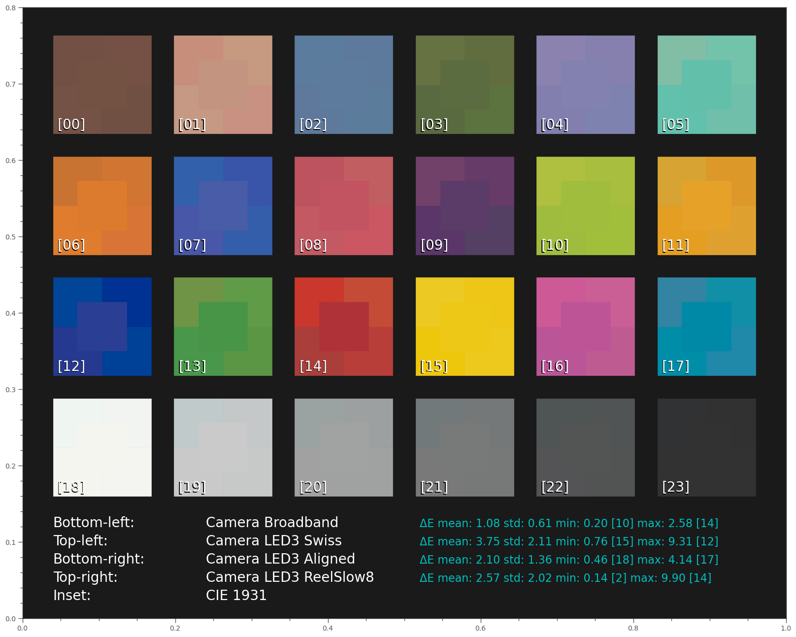
already giving some insight into the situation. The simulation was done the following way: I assumed a color checker being illuminated by various light sources. The color checker was recorded by a standard HQ camera with standard IR-blockfilter. This is not exactly the situation we have in a film scanner (reflective vs. transparent target, print dyes vs. film dyes, for a start), but I thought it would give at least some hint what one could expect.
For each light setup, the color matrix was individually optimized to achieve the best overall result. In the center of each patch, the color is displayed which a human observer would perceive when looking at the color checker in normal daylight.
The bottom-left subpatch shows how the HQ sensor would “see” the colors with the same illumination. Clearly, there are some differences, but the mean ∆E-error is remarkably low, only 1.08. (It would be slightly larger if the color matrix would be directly from the tuning file.)
The other patches show the best results with different narrowband LED illuminations. “Swiss” shows the result with the LEDs quoted in the Diastor-paper, “ReelSlow8” the results with the LED-setup given by @npiegdon quite some time ago in this forum. “Aligned” shows the results of another LED configuration, somewhat hand-optimized for the task at hand.
While this simulation shows certainly the trends one would have expected, the simulation is not really equivalent to our film scanner setup, as mentioned above. I want to get some more insight here before I start considering to change/optimize my scanner’s illumination source. That is: before I fully dismantle/redesign my scanner.
That’s enough information for I was looking to do.
Sounds like a plan.
I am close to have the first version of Snailscan-Too actually be good enough for initial scanning, and the plan is to then redesign the LEDs to better fit the sphere (which in my case is a bit bigger for 16 mm scanning).
Understood. There is some alignment, since I would like to test/experiment with film. At this time my approach is to capture raw-raw (linear values direct from the sensor -same light intensity for all 3 or individual light for each) and use/let Davinci Resolve do the color pipeline.
The goal of redesigning of a V2 sphere is to have multiband and white, and be able to experiment with different setups under the film setup.
Would it be helpful to have mechanical drop-in replacements (10mm x 10mm)? or would you prefer to wait until the redesign?
The primary reason to do the ultra small factor of 10 x 10 would be to make it a mechanical replacement for your project, In general, I think a slightly larger PCB would make it easier to dissipate the 1W power of the LED.
The LEDs that I plan to pcb (already have 7 bands on hand) for the multiband are this series.
I think the collective will benefit from a high-quality light/high-intensity small factor LED, and having the know-how and capability to make a run (when doing other PCBs) would be a way to get back to the collective from all the valuable information, especially your insight into the HQ. The Scientific file was a game changer for the ability to use the HQ. Thanks again!
Edit: perhaps we should start a topic for Color Science / Illuminant Experiments.
Well, due to time reasons, I guess it will take a while until I will work on modifying hardware. So I think at this time it makes no sense to do a 10x10 PCB.
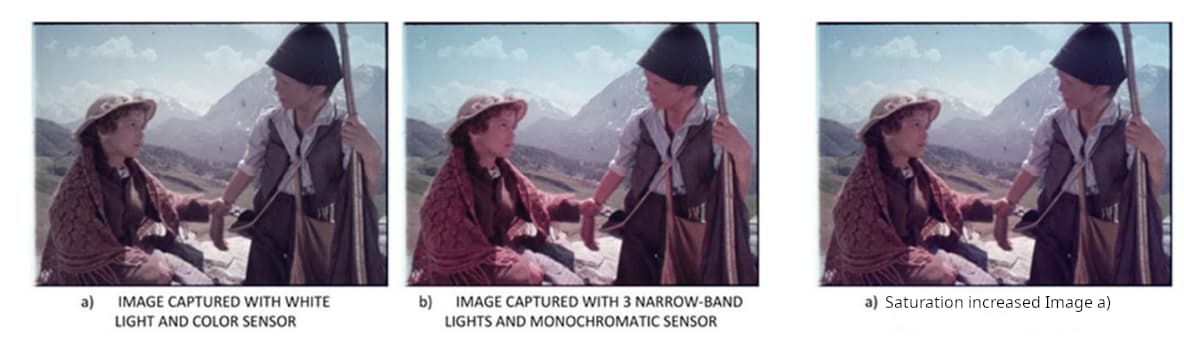
Changing subjects a little bit: the discussion whether narrowband LEDs should be preferred to wideband LED illumination is still not solved. Like @npiegdon, I was initially pushed into the corner of a narrowband setup after reading the DIASTOR paper, overlooking the warnings of @friolator. The comparision of a wideband scan vs. a narrowband scan (on page 15 of the paper) were too convincing.
Well, if you accept the fact that you have to do anyway a little color grading after the scan, here’s an interesting outcome of a little experiment I made:
The rightmost image (I added to the show) is the “Image a)” (wideband image), with just with a little push of saturation applied. Skin tone-wise and as well with respect to brown tones, I think it easily beats the narrowband result. So the main claim of the paper at this page, “no processing would retrieve those colors from the image captured with white light”, I would not underwrite.
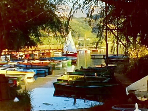
Using a LED setup quite similar to the Swiss one, I did further encounter funny effects: with certain film material my scanner was seeing structures in the scan which were simply not noticable by human observers. Here’s an example showing a red glow around the edges
(I have no better image left - this was years ago.):
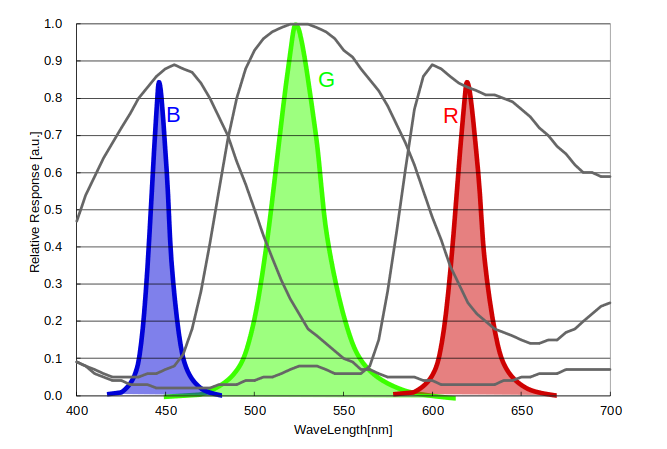
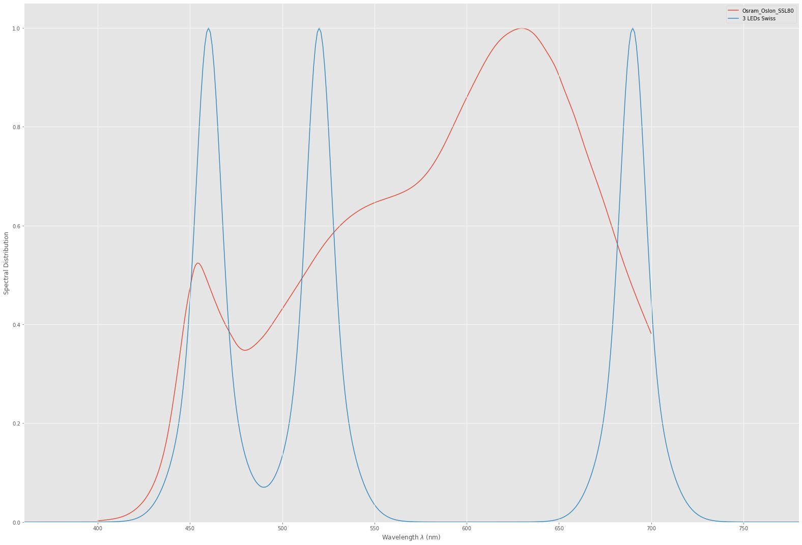
This spill was only present with that specific S8-camera. I traced the issue down to an too extreme selection of the red LED. Here’s the spectrum of the Swiss setup compared to my currenty broadband illumination:
The initially chosen red LED was really at the edge of the visible spectrum and that caused most probably this issue.
After replacing the red LED with a one shifted closer to the green channel, this issue was gone.
Anyway, I learned that way that you sometimes might not be interested in an illumination having too much color separation between channels.
Since the colors did not come out very well from the scanner even with the red LED adapted, no matter what I tried, I finally gave up on narrowband LEDs. The way @npiegdon went with his setup (calibrating with a known color checker slide) is not possible with my scanner design (not enough space).
So in the end, I abandoned the narrowband setup and switched to a broadband illumination. My thinking was the following: originally, the S8-film would be viewed by a human observer, projected with a Tungsten lamp-like illumination source. Using in the film scanner an illumination source as close as possible to the old projectior’s lamp, the frame in the film gate should be close to what a human observer would have seen in the old times. If in addition I could come up with a camera setup recording such an image as faithfully as possible, I would be done. That was the birth of the scientific tuning file.
At that time, I was using still multiple captures because of the large dynamic range of color-reversal film. The disadvantage of such an approach is the increased capture time compared to a single capture. After raw capture was available in the RP-software, I switched to single raw captures, in turn speeding up the capture process substantially. Immediately it became obvious that a single raw capture is scratching on the border of being usable, at least with the HQ camera. Horizontal noise stripes limit the usability. I convinced myself that that with my film material, this was managable, due to the postprocessing I am employing. Other solutions were proposed by @npiegdon and yourself (@PM490). My current plan is to stick to my current whitelight illumination; as another project I am after (monitoring small movements between film and camera gate) anyway requires the capture of multiple raws (this can be done without too much time penality). I will try to implement averaging several raws like you and @npiegdon already suggested.
I’ve been trying a couple of different light setups during the past days and am having the most frustrating experience.
As soon as I have any kind of encasing around my light source, or maybe, on the opposing end, some sort of “tunnel” towards the lens, I can not arrive at a shutter speed which simultaneously exposes the center of the frame evenly/properly but does not at the same time turn the borders below the black level threshold.
When I leave everything “open” (i.e. light source bigger than the gate), there are constellations that leave the image with just about enough haze so that the center of the frame is properly exposed and the borders are not entirely black. Unfortunately this also tends to introduce a purplish color cast with varying intensities depending on lamp-diffuser-distance etc. It’s finicky.
So, somehow, I need to arrive at a setup that does not turn the frame borders black, but also does not overexpose the center… Could you kindly post a few examples of your working light setups for me? I’m running out of ideas… (I also don’t have access to a 3D printer, so I pretty much have to work with DIY and salvaged parts. It’s a bit limiting).
I’m using the scientific tuning file. Does ALSC still apply?
Edit: Would I need to adjust the ALSC Matrix to adjust the border gains or am I looking for the wrong thing here…? It’s definitely scattered light that the lens is picking up when I don’t use some sort of enccasing. It’s also across the entire image, not just the edges.
No. At least in the original version, there is no ALSC section at all. Haven’t checked lately, but this section should not be present. That was one of the important modifications of the scientific tuning file.
Your problem might be caused by the illumination itself. Have a walk through the forums for various solutions without a 3D-printer, like integrating spheres out of kitchen stuff or various type of plastic diffusors. Check how even your illumination is with another camera if possible.
The uneveness could also be caused by the lens you are using. Or your setup. Some kind of illumination requires an appropriate field lens for proper operation.
For various reasons, I recommend a diffuse lightsource. Best approach here are integrating sphere setups. Or very good diffusors. Sometimes it helps to use several sheets stacked together. Such a setup kills brightness, so be sure to work with a sufficiently bright illumination source.
And please: your request has nothing to do with the original topic. Open a new topic. In that way other users are also able to search for and find things easier. Concerning your original question: a photo of your basic setup and of the results you are getting would help others to comment better to your question.
As Rolf @cpixit pointed out, these unusual encounters appear in very different setups.
Being able to create the banding in the above experiment, my next step was trying to determine the source.
To frame the experiment, I have been working with the HQ in what I would call raw-raw-binned, meaning that I use the picamera2 function
The resulting array is 4064 x 3040, in the form of provided by the raw format SRGGB12, and it is not affected by the color processing pipeline of the picamera2. In other words, the setting Red and Blue Digital gains “ColourGains” have no effect in the output data.
The raw Bayer color pixels are then binned into a 2032x1520x3 RGB image, where G = Bayer G1 + Bayer G2. The image is saved to a 16-bit TIFF using python tifffile library.
Unlike the DNG, there is no color information other than the raw quantization binned into the array. Another important differentiation is that there is no subtraction or removal of the black offset present at the sensor, and also that it is a linear image, there is no gamma correction.
Another component of the experiment is that the white LED power is a constant-current source driven by a 16bit DAC. That component was key to adjust the light to only slightly lift the level of the sensor above the clipping.
Experiment
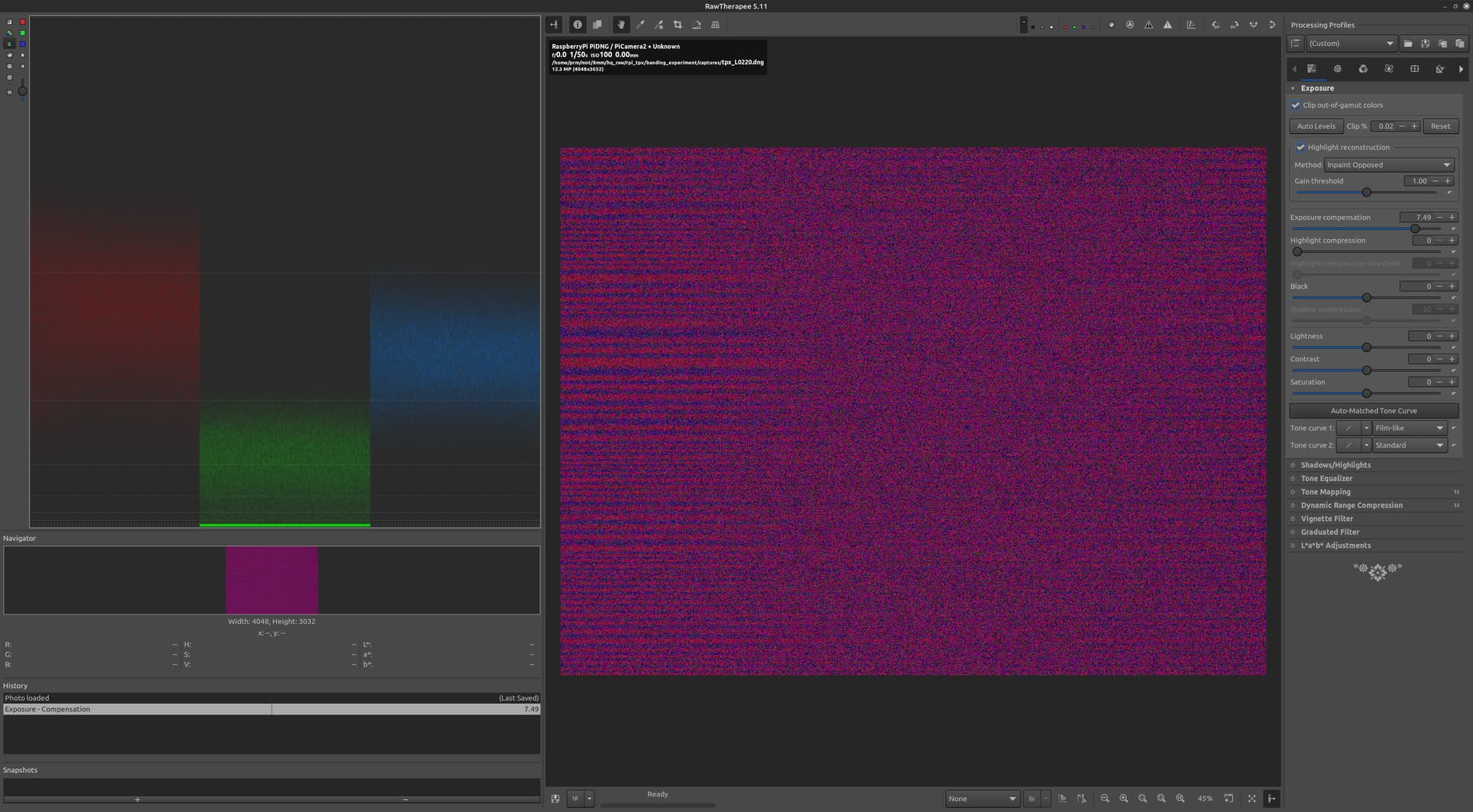
Set the light and exposure for the banding demonstrated above with the normal libcamera2 DNG pipeline, and capture a DNG with the banding.
Then, using the same light and exposure, capture a 16bit TIFF via the raw-raw-binned processing pipeline, and completely disregard the picamera2 color processing.
Results
It was possible to reproduce issue in the DNG file.
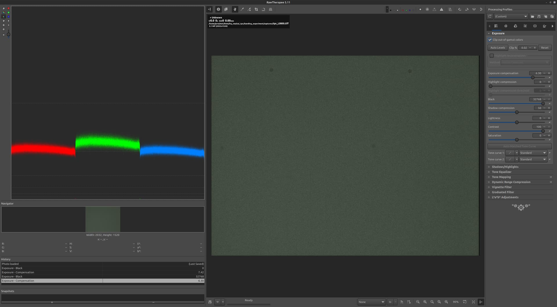
I would point out that the amount of gain necessary to bring these up is massive, compared to what we see in the DNG.
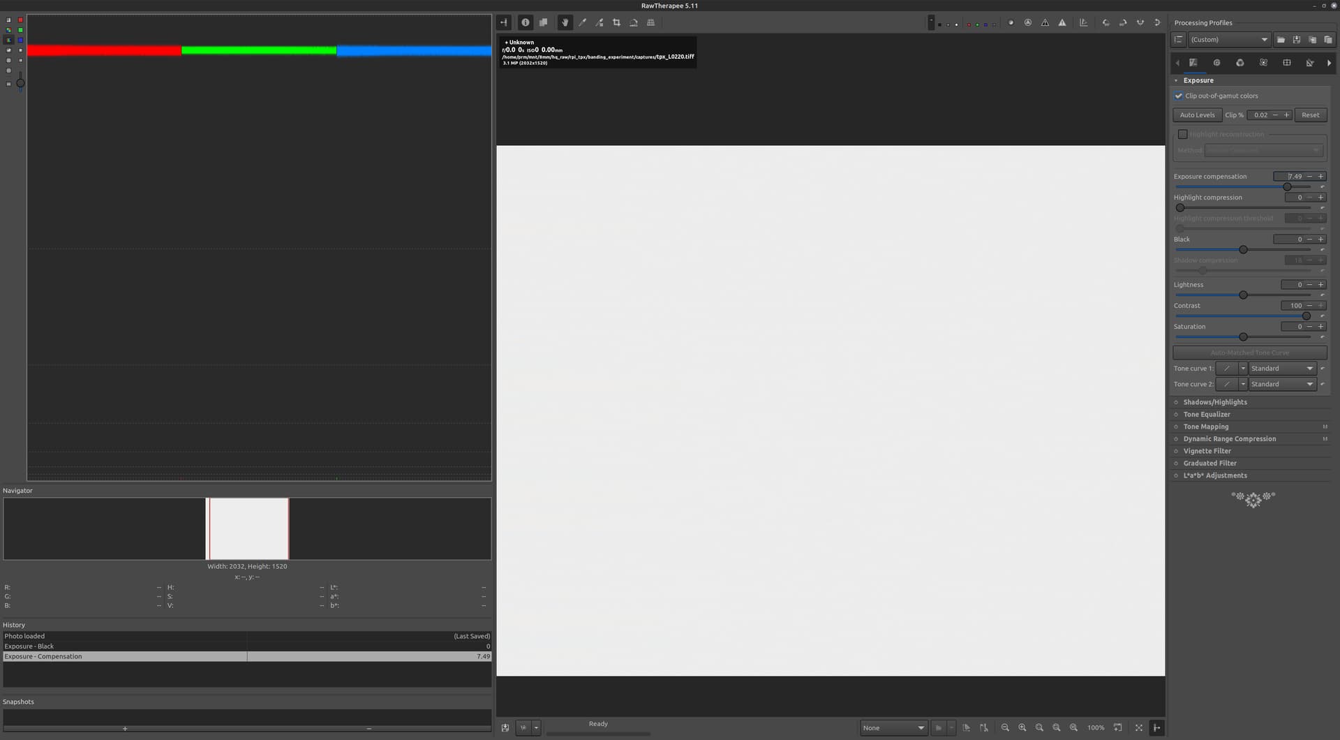
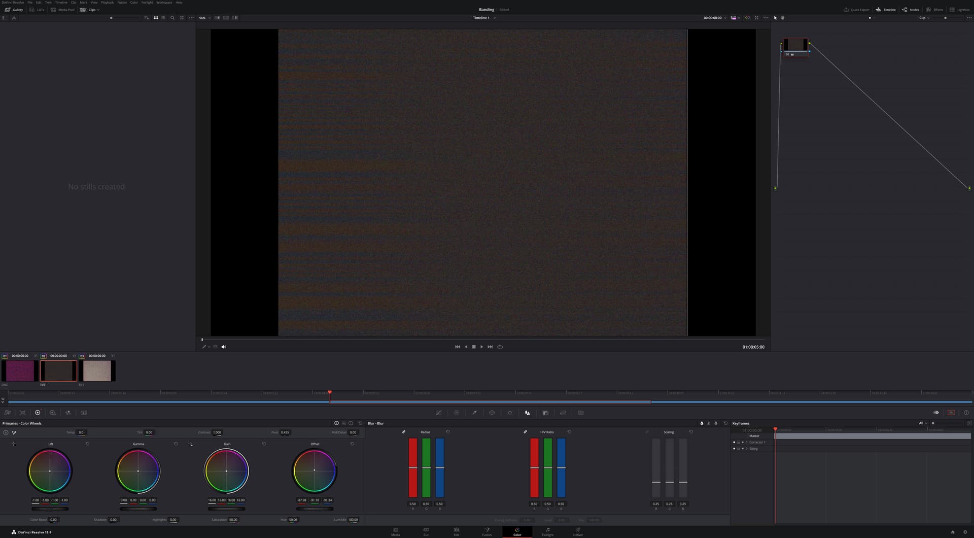
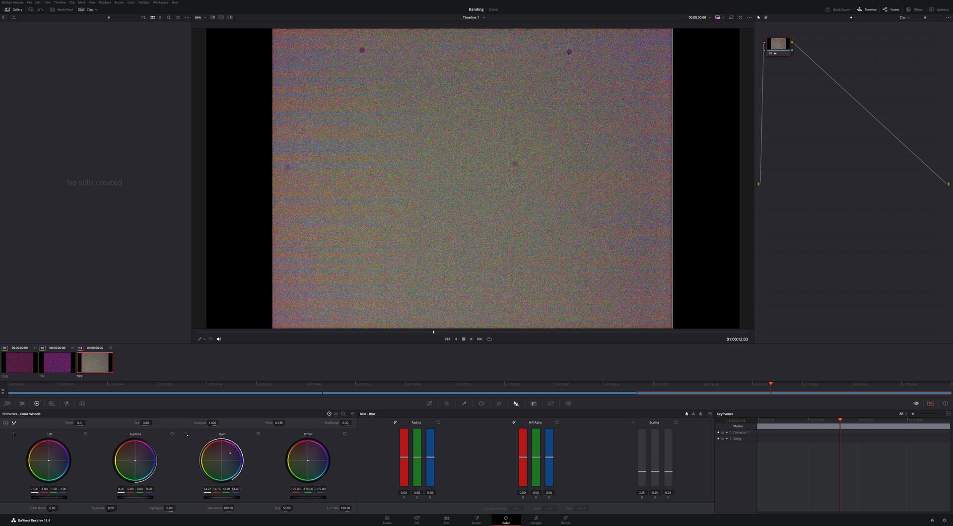
I did notice that the amount of light is so little that one cannot see the light/lens defects, it is almost like a bias level to the sensor. To test what would it look with a slightly higher light input, here is another capture with raw-raw-binned TIFF.
With slightly more light, the lens defects are visible, and the color levels are not equal (as expected from the binning). It is safe to say that we are -slightly- above the black clipping level. Notice that the black slider had to be adjusted to bring the levels down.
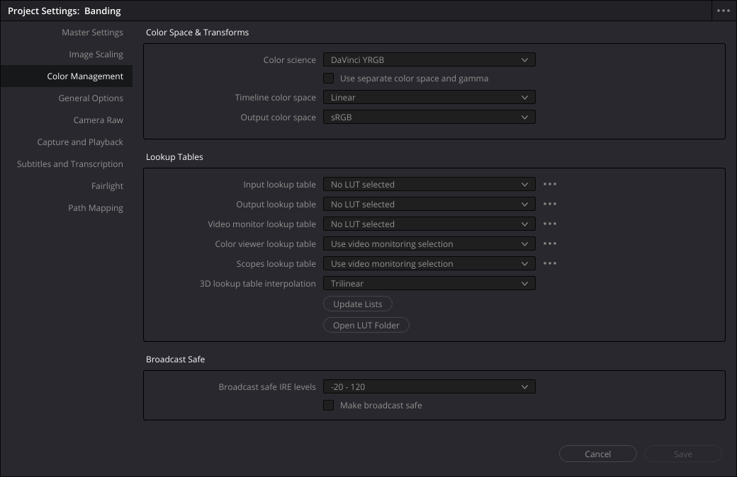
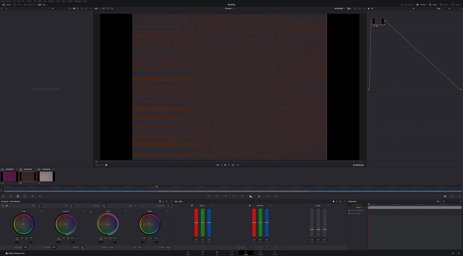
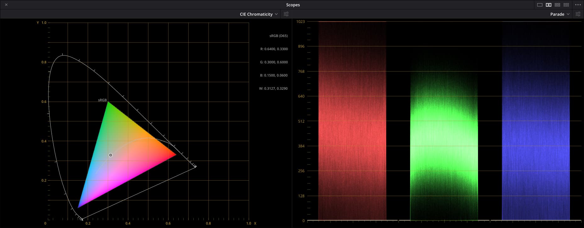
Now the same above file to Resolve.
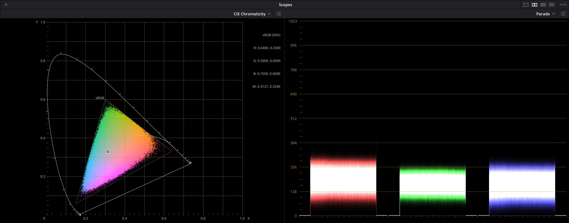
Notice that to obtain the image, I set lift and Offset to minimums, and adjusted gain to bring the levels within the range. On this one, I could not touch the Color Boost, doing so would result in a flat green.
Conclusions
The results are consistent with the banding pattern source being the mechanism for black-clipping at the sensor.
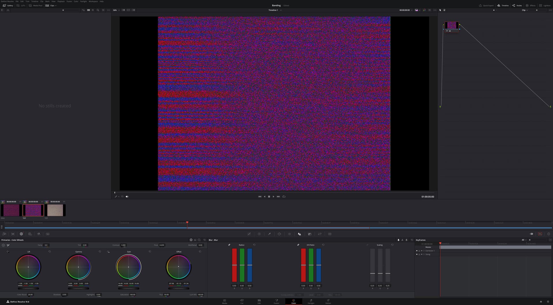
The banding obtained using the alternative processing path of raw-raw-binned 16bit tiff required extreme settings of gain in Resolve and produced quantifiably less intense banding.
One hint was that, under these extreme gain-lift-offset settings, a slight use of the ColorBoost setting would burst the TIFF color banding similarly to the typical results with the DNG.
Unsolved
While this appears to confirm that the root cause of the banding is the sensor, it left unclear why/how the picamera2 processing pipeline makes it so much worst. The gain settings of the picamera2 (ColourGains) are an order of magnitude lower than the experimented setup with the color-tab gains in Resolve.
The files used above, and the reference screen-shots were uploaded here, in the event that someone wishes to experiment. The LXXXX corresponds to the DAC LED setup for the capture.