Strange encounter in the red channel/RPi HQ Camera

… slowly approaching a “solution” to the issues discussed in this thread - in a way. I want to present in the following a few images and discuss them. I hope my musings might be helpful to others…

Does it matter?

The two things discussed here and elsewhere are out-of-gamut colors and stripes of noise in very dark areas. I think these issues are not important generally. To make my point by an example, have a look at this image:


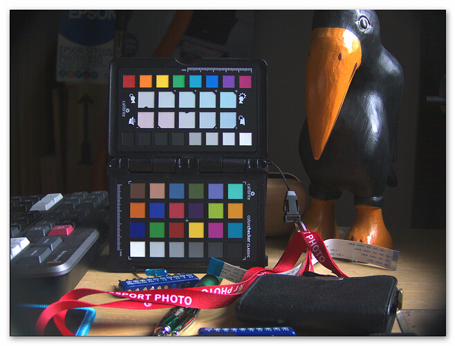
In the top-left, the raw .dng-file was processed in a standard conforming way into a rec709/sRGB image. It’s a daylight capture of a carefully arranged desktop scene - and in my opinion, it looks just fine. There’s only one obvious burned-out highlight on the beak of the bird but otherwise, the colors of the color checker look just fine (they are, I measured them).

In reality, this image has the same issues we discussed at length - noisy stripes and out-of-gamut colors. They are marked in the three other versions of the image, channel by channel. Everything below a certain threshold (<1/2046) is marked with yellow color, everything close to the maximal intensity (>1-1/2024) is marked with red.

The first thing to notice is that the color checker patch no. 17 (cyan) is below the lower threshold, completely marked yellow. In fact, it has to be, because the color of this patch is outside the rec709/sRBG color gamut. Searching for more yellow stuff, we easily discover in all channels our stripes of noise. Remember, this image was taken in pure daylight - so no issues with any unstable illumination.

Looking at the red areas, we discover that in addition to the beak of the bird, other areas are burned out - different ones in different channels. Again, these areas indicate out-of-gamut colors. But: did you notice any of this when looking at the original picture?

That’s my point in this section: the out-of-gamut colors usually will go unnoticed in most situations, as will the stripes of noise.

Exposure

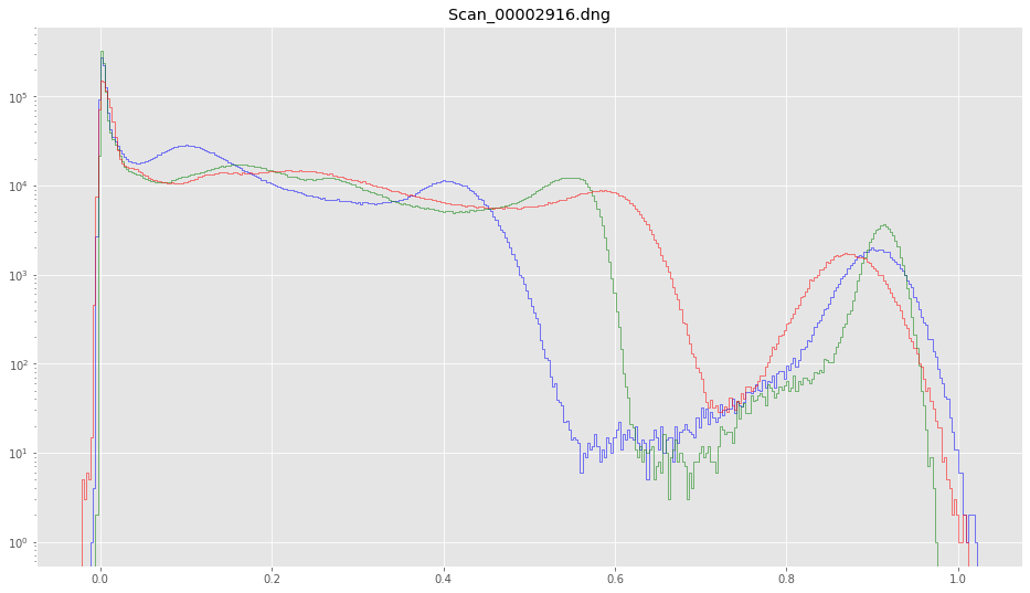
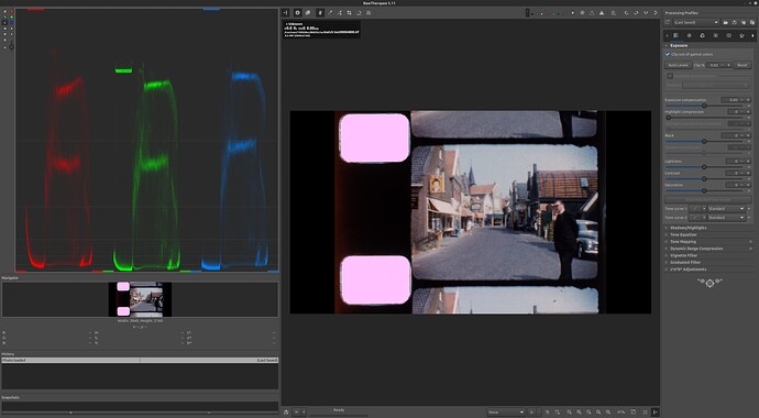
Let’s look at a real film scan, Scan_00002916.dng. The histogram of this scan


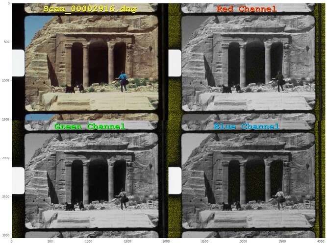
shows that there should be no out-of-gamut colors - everything stays within the interval of valid colors, namely [0.0:1.0]. Looking at the green trace, we see that the pixel values of the real frame are from slightly above 0.0 to approximately 0.6. The values above that correspond actually to the sprocket hole, with the maximum at around 0.95. Ok, and here’s the corresponding image:

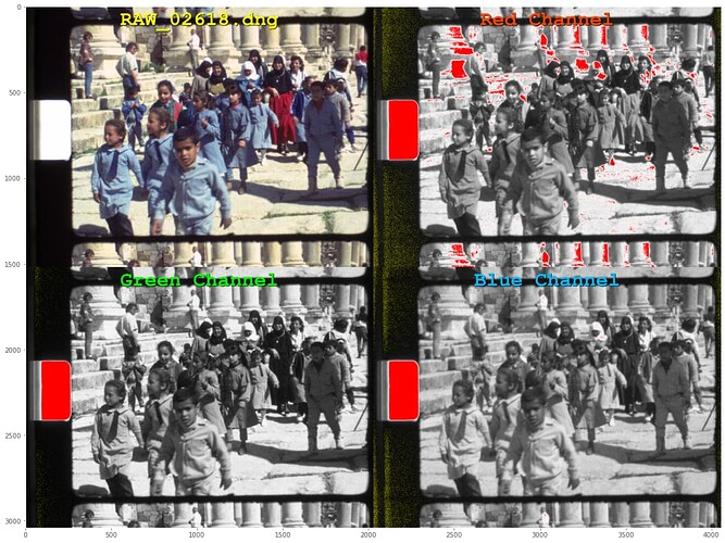
The stripes of noise are there, but mostly confined to the area outside of the actual frame. This is almost good, save of the fact that we throw away with that exposure setting half of the (linear) dynamic range of our sensor.

I usually use a slightly higher exposure value, one which does not try to digitize the sprocket hole values. Here’s a corresponding histogram of such an exposure:


If you compare this with the previous histogram you will notice that that the pixels of the frame image reach much further towards the limit 1.0 - in our case the maximum in the red channel approaches something close to 0.9. Here’s the corresponding image:

The same situation as above, only that the sprocket hole is now marked as overexposed.

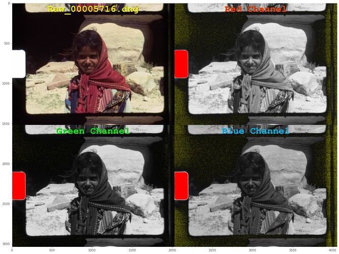
This is actually the exposure setting I am working with - mostly. It has a slight probability of causing burned out areas in the actual film frame, namely if again out-of-gamut colors are encountered, but as I mentioned above - no one will notice.

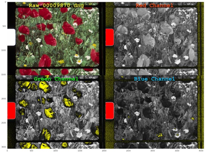
Here’s an example:


The poppy flowers lead to out-of-gamut colors (yellow marked) in the green channel, and we have a few intense yellow daisy colors which are marked again yellow in the blue channel.

Here’s an example where this effect happens in the red channel:


I know that this is happening, but I do not care. The improved dynamic range is for me more important than the slightly reduced fidelity in these areas.

Forum data

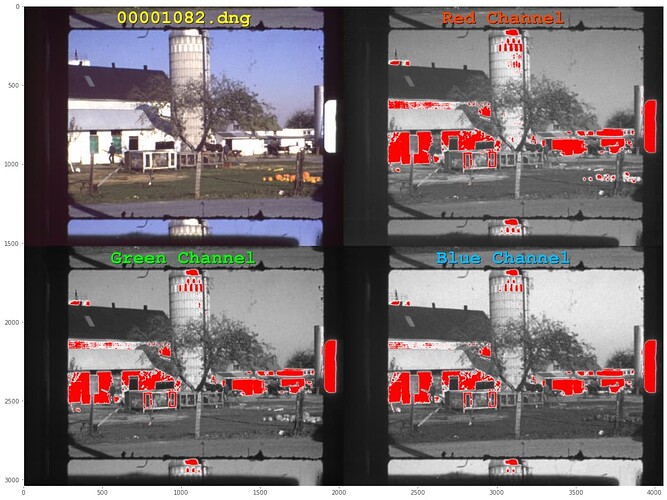
While we’re at that, I thought it would be interesting to have a look at some of the data posted here on the forum. Here’s 00001082.dng (@verlakasalt):


No noise stripes, as the frame border is rather bright, but heavily burned out image areas in the brighter parts of the capture.

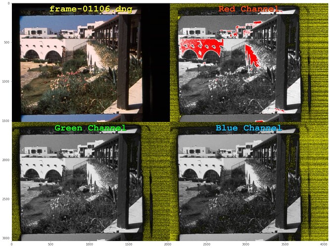
Now, ‘frame-01106.dng’ (@Manuel_Angel):


There’s no sprocket hole, but a few areas of the house wall clip in the image. Noisy stripes are there - but again, both issues are not noticable in the real image top-left.

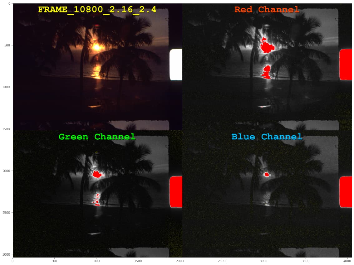
Continueing, let’s look at FRAME_10800_2.16_2.46_R3920.0_G4128.0_B3952.0.dng (@verlakasalt):


This is the type of images which challenges the dynamic depth of our sensor quite a bit. There’s highlight clipping in all color channels, but again, not noticable in the real image. Stripes of noise are also there, but very faint.

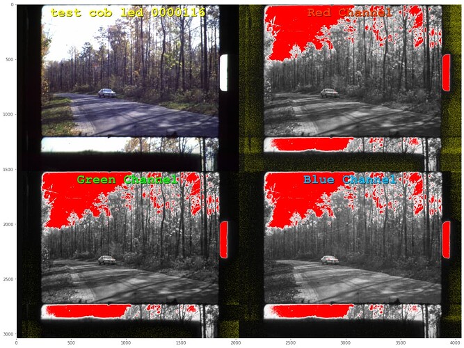
Next, test cob led 00001160.dng (@verlakasalt):


Clearly, an overexposed film scan. Lots of noise, especially in the red channel. The red channel operated on a gain of 3.12 - that’s a more than two times higher gain than the blue channel.

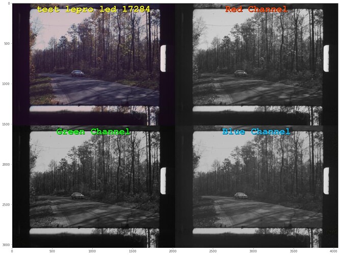
A similar frame was captured in test lepro led 1728464695.2264783.dng (@verlakasalt) with another light source:


Here, the red gain was 2.02, the blue gain 2.8. No noisestripes at all, probably because again the really dark areas of the film are not dark. For whatever reasons. Note that the white balance was quite off in this capture - there is a visible magenta cast all over the frame.

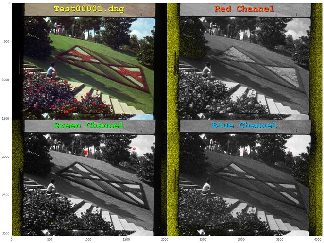
The following image, Test00001.dng, (@Manuel_Angel )shows our usual setup:


That is, noisy stripes outside of the area of interest (the film frame) and a barely noticable burn-out in the green channel (in the sky).

Seemingly the same image comes from Test00002.dng:


The real image (top-left) looks almost identical to the Test00001.dng image - but note that a lot more areas show some close proximity to the maximum image brightness (all areas marked in red).

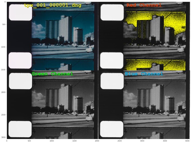
Continueing, here’s tpx_001_000001.dng (@PM490):


There is quite an amount of noise in the red channel, but noticably no noisy stripes. That is probably caused by a dynamic range in the red channel exceeding the 12 bit of dynamic range the HQ sensor is capable of. Note that the sprocket hole is exposed correctly - the real image data is occupying only a fraction of the available dynamic range, as discussed above.

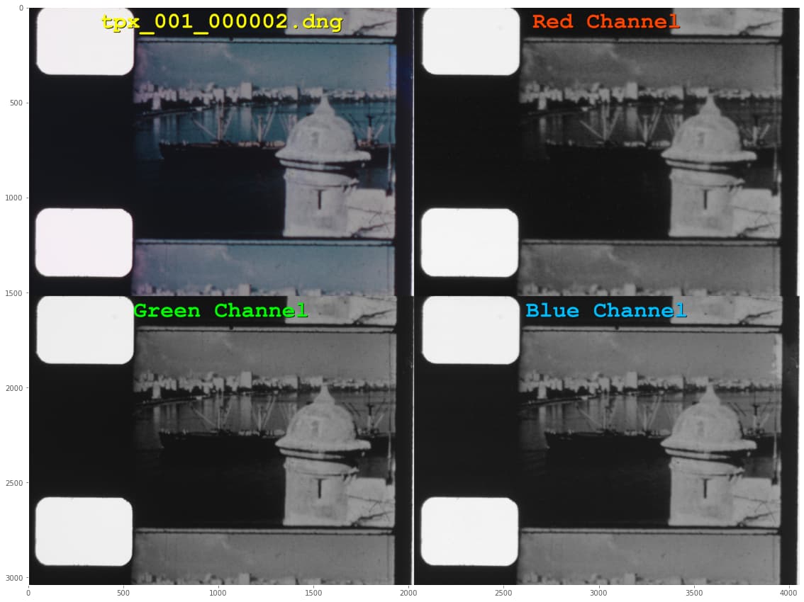
In comparision, with other image content and presumably the same setting, in tpx_001_000002.dng (@PM490) we see no noise at all:


Nor any other issues. Still, since the dynamic range is not optimal, the grading of this image might show banding effects if extreme measures would need to be taken.

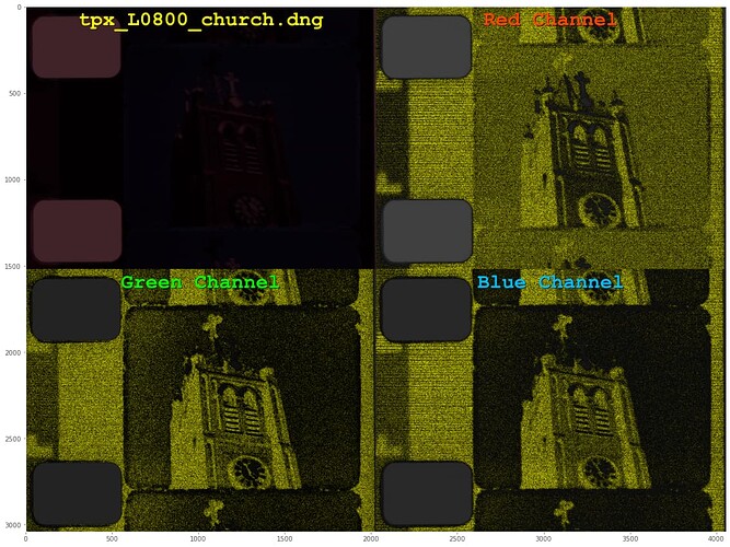
In closing, here are some testimages analyzed the same way as all examples above. First, tpx_L0800_church.dng (@PM490):


This image was severely underexposed on purpose. Noisy stripes are visible in all channels. Somewhat interesting, the red channel seems to be a sort of negative of the blue channel.

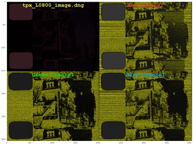
The same effect can be noticed with tpx_L0800_image.dng (@PM490):


But note also that the characteristics of the noisy stripes have changed in comparision with the previous image. I have no idea what might have caused this.

Ok, that’s it for now. Hope you found this little journey somewhat interesting.

3 Likes

Would I be being difficult if I said I did? :sweat_smile:

Mostly I noticed the blue cast on everything. I don’t have the original 16-bit image, but having a color checker right in the frame is enough. If you use Resolve’s “Color Match” feature to get the real colors back out, it looks much nicer.

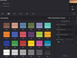
That little color chart icon at the far upper-right of that screenshot in the viewer area is the important part. Switching the qualifier to “Color Chart” lets you move each corner to match the chart in the frame. Then, choose the right chart from the drop-down–in this case X-Rite ColorChecker Classic–and finally the “Match” button.

That gives automatic, beautiful colors. No more blue cast. (And the bird’s beak and red lanyard strap look super cool on a wide gamut monitor… but that’s beside the point.) :rofl:

1 Like

:sweat_smile: fair enough, if you insist. The image was taken and developed with the auto-whitebalance gains of libcamera/picamera2. That’s indeed a little blueish. If I would have developed it with using the whitebalance from one of the gray patches in the image, the colors would have ended up like your colors. However, I developed each of the images above on purpose with the whitebalance used during the capture.

The original dng.-image is linked here.

Note that the largest error DaVinci detected is in the cyan patch - which is out-of-gamut in sRGB. So this color will not be reproduced faithfully even on your wide gamut monitor. The same goes for the strap and the beak. They might look great, but they are not the true colors. For this to achieve, one would need to use a different ccm than the one the camera embedded in the .dng. All examples above did however use the embedded ccm for development.

1 Like

Doesn’t the “Color Match” feature essentially bypass everything else, regardless of original shooting/processing conditions? Isn’t that the point of shooting with one of those targets in the frame?

It’s like the shot matching demo from the awesome Daniele Siragusano video (at the 6:50 mark) that you shared in the Color Magic topic. It doesn’t seem like the original shooting conditions mattered that much there, either. (I wish that Baselight app he was demonstrating wasn’t $300/yr…)

Well, I think it’s kind of complicated. And the davinci manual is not of much help here.

But stick with me and do the following experiment. Add another color processing node to your grading tree (ALT-S on Win machines). Switch off your first node by clicking on the tiny number, “01” of the node symbol. Select again the second node (labeled “02”).

Now select the “Color Chart” overlay in your previewer in the “Color” page and mark the color chart again. Than go down to the “Color Match” tab and click “Match” (the defaults are “X-Rite ColorChecker Classic - Legacy” (in this case the correct choice) and “Source Gamma”, “Target Gamma” as well a “Target Color Space” leave on “Auto”).

Davinci will happily do a color match on this second node. How come? Because the color matching function is a node-function. In fact, you can switch on and off each of the two color match nodes and play around a little bit. So…

What that tells me (and again, I have not found any reference in Blackmagic’s manuals for this) is that this color match functionality is simply a node-function. As we have seen, it can be switched on or off with the node. And you are asked to specify a source gamma. All hints that this is not connected to the input module of the node tree (the tiny rectangle with a green dot on the very left of your node tree). So you cannot recover what the input module has already screwed up. Or the image data you have available. Since you tried this with the .png image I posted, you should have rec709 as a basis. And I know that the cyan-patch result of 12% match grade is very typical for rec709-based workflows, as this patch features an out-of-gamut color. So it’s easy to interfere that the other out-of-gamma colors, including the strap and the bird’s beak, cannot be magically recovered by your operation. Hope that clarifies my above comment.

As I linked to the original raw image above, you can try the color matching stuff again on that image.

This was an interesting exercise.

Using the original DNG

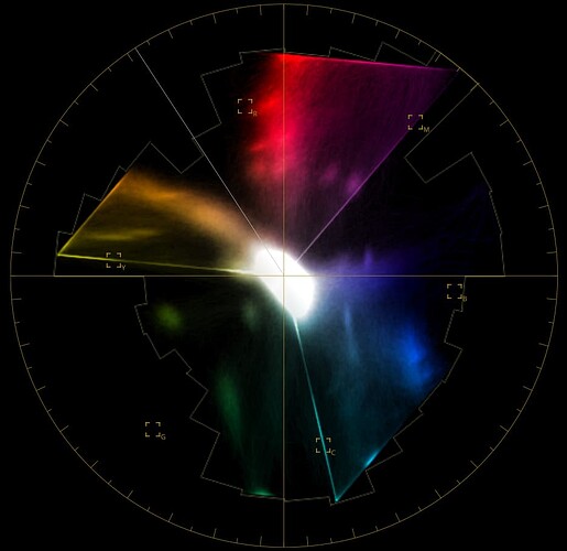
  1. Just dropping it in to the media pool, creating a new timeline from it, and then doing nothing else, the color was much better than the blue’ish cast JPG. Like, post-“Color Match” good without doing the color match. But the vectorscope is strange. The C, M, and Y lines are too perfect and the diagonals coming off them are unusual, too:

  2. Trying to apply a color match ruins everything:

  3. Switching the Camera Raw tab to “Decode Using: Camera metadata” and then applying a color match reduced the saturation considerably. It was closer to “normal” color, but still worse than just dropping the DNG in.

None of that was expected behavior. My inexperience with using the DNG/RAW workflow in Resolve is probably to blame. I’m guessing something somewhere is still linear when it shouldn’t be.

Using the sRGB JPEG from above, cropped

  1. Dropping it in and making a new timeline gives exactly what I see (blue’ish cast) in my browser above. The scope looks like a normal scope where you can see (clockwise from 9) the desk/beak/lanyard along with the individual patches the way you’re supposed to be able:

  2. The first Color Match makes it look great.

  3. Performing your experiment (an additional node with an additional color match, toggling them, etc.) results in exactly what you described.

Now let’s try one additional test: enable both nodes. At first, the previous color matches will be “doubled” and things won’t look right.

But if you choose the second node and click “Match” again, something interesting happens: everything looks good again. Now, toggling the second node results in no change. It’s effectively a null transform.

To me, this lends more evidence that Color Match is more of an “absolute” transform (rather than something “relative” to a particular input). It takes any input and corrects it to as close to the right answer as it can get. For the second node, the input is already as close as it can get to the right answer and it doesn’t need to change anything.

So I would agree that post-Color Match, the input node in the tree doesn’t matter anymore. I suppose that makes the answers to the questions I asked last time “yes” and “yes”. :wink:

Well, I opt to disagree. Play a little bit more around with that stuff. For example, do the color match on a first node, a mild color grading on a second node and a final color match on a third node, with the sRGB image as starting point for the first node.

You will see that the third node, the second color match, will undo your little color grading in node 02. For example, if you pushed the gain of node 02 towards green tones, the node 03 will correct it again. Now switch off node 03. You will see the greenish tint produced by node 02. Next experiment: switch off node 02. Since the color match on node 01 created “perfect” colors, this is what you see (as both node 02 and 03 are off at the moment). Finally, turn on again node 03’s processing. The image turns magenta (the negative of green), because the node 03’s color correction is tuned to the greenish node 02 output - but that one is currently switched off (if you followed the recipe).

So again: this color match function is a node-based functionality. You can do it several times along your node graph, if you have the desire to do so. Every color match is independent from the other color matches. In your terminology: “relative”.

And: as any node comes after the input node (the little rectangle with the green dot), in the case of raw images the ccm from the .dng-file is already applied to your data. There is no way around this.

Yes, if you pull the rug out from under it, of course it will be incorrect. The color transform (essentially a custom LUT) is calculated when you click the Match button. The solution is to click Match again whenever anything changes upstream and you’ll never run into any problem like this.

(That we’re applying a Color Match after doing any grading is already a strange premise. Color Matching is always first. Grading to taste comes after you’ve established good scene colors using the card. The 3rd node in your experiment is simply undoing your work in the 2nd node.)

I’m not sure if you’re suggesting it would be better if it was constantly updating anytime some other node changed, but for an interactive, manual process where you have to locate the card in a particular frame, it doesn’t make any sense to automatically update.

This was exactly my workflow for every shot of the vibration sensor video. The card is in the frame when you hit record. Color match first with the raw footage. Any changes for personal preference come after that. Everything works great. Lovely color.

In that case it was in Premiere, not Resolve. And I was using a plugin called MBR Color Corrector because Premiere doesn’t have a Color Match feature built-in. In that case one of the steps is literally to save out a .cube LUT file that the plugin generates from the in-frame color chart. So maybe it was the more explicit, separate step that seems to have made this such a clear-cut case in my brain?

From what I can tell it works exactly the same in Resolve. The “Match” button is one-time generating and applying a created-on-the-fly LUT to that node that attempts to most closely match that node’s (current) input to the reference chart data for the card that was selected.

Everything you and I have posted so far supports the preceding paragraph. So much so that I’m not particularly clear on what it is you’re still disagreeing with.

Well, I think we were discussing different things. You are absolutely right that a color match is/should be usually applied only at the very beginning of a grading tree of a clip. This can solve illumination as well as camera/film differences. I myself used color charts already in the 80’s of the last century for reproduction work, with analog cameras and film.

I think the color matcher is not generating a general LUT, but only a 3x3 color transformation matrix - for example, the color match function of davinci cannot really counteract a log-transform. Which a general LUT could easily handle.

Now. While the general usage of a color match would imply that it is tied to the clip in question, within davinci it is not. Let me elaborate that. If you create a new node, you can readjust quite a lot of things within that new node, only affecting the nodes after this new node. Examples are “Gain”, “Curves - Custom” and “Color Warper - Hue - Saturation”, to name a few. A very important one is the “Color Space Transformation” which is used a lot by professional graders. You go for example from rec709 to log space, do some intermediate grading, and finally go back from log-space to rec709. Clearly, each node has to do it’s work independently from other nodes.

However, there are functions which are not tied to a specific node, but tied to a clip. I know of at least two: first of all, what is set in the “Camera Raw” tab of the “Color page” is tied to the clip. It does not matter which node is selected when you change settings here - it affects the clip as a whole. The same goes for the “Tracker - Stabilizer” tab. Whenever you change stabilizer parameters, it does not matter which node is selected - only the clip matters.

It’s of little help that this is not clearly stated anywhere in the manual of davinci (as far as I know), nor that such functions are not differentiated somehow in the user interface.

Now we are coming back to one of our main discussion points. The “Color Match” functionality might certainly be considered “clip-related” - but that’s not how the function is implemented in davinci. It’s connected to a single node, so you can have multiple independent color matches in a processing tree. Why they implemented this in that fashion - I do not know.

So the answer to your first question:

is actually “no”. It’s not included in the “clip-only” functionality.

Well, usually. In a mixed light situation, you might want to treat different parts of a scene separately, depending on the light situation. That would ask for several strategically placed color checkers. But I agree - it’s not clear why the “Color Match” functionality is node-based.

Which brings me back to the start of our discussion. While the beak of the bird might look great on your wide-gamut display, the display is based on a rec709 image which simply does not deliver colors outside of the rec709 color gamut. Even if the source material would deliver these colors, the “Camera Raw” module would by default map into the rec709/sRGB gamut, with those colors outside of this gamut clipped.

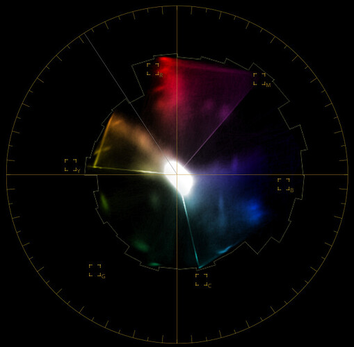
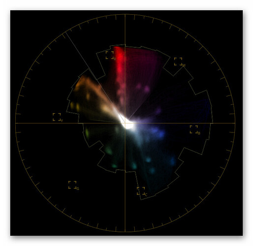
The xp24_full.dng is an extremely demanding image. Your vectorscope display


shows clipping all around the borders of the color hexagon (the sharply defined straight lines).

What I have been able to come up until now is this here:


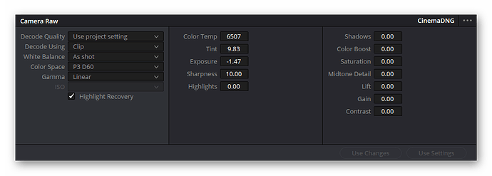
which is a slight improvement, but not yet satisfactory. I used in color time line settings as “Color science” DaVinci YRGB with the “Timeline color space” set to Rec.709(Scene). The “Camera Raw” module was set to “Decode using” Clip, “Color Space” to Rec.709 and - that is important - “Gamma” as Linear.

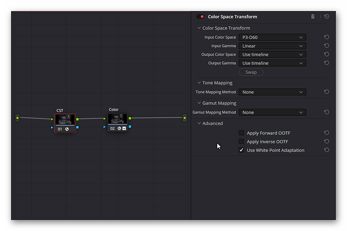
The input is transformed into the appropriate color space by a “Color Space Transform”, with “Input Color Space” set to Use timeline, “Input Gamma” selected as Linear and “Output Color Space” as well as “Output Gamma” set to Rec.709.

That is not a massive improvement, to state it politely. Davinci is somewhat limited in standard raw image formats. Also, to enhance libcamera/picamera2 would be no easy task. Maybe an external program to convert .dng-files to linear or log 16bit tif-files with a defined color gamut could be a way to go forward. We will see!

1 Like

Just to clarify this for whatever it’s worth: The magenta cast comes from not encasing the bulb. There was a massive amount of scattered light when capturing the frame. (White balance wasn’t optimized either, but that’s not the cause).

Edit: Found this regarding nodes in DaVinci, but it probably doesn’t affect the RAW tab.

“Node flow goes Group Preclip>Clip>Group Postclip>Timeline”
Reddit - Dive into anything

1 Like

That explains the absense of the noisy stripes. The scattered light reduced the dynamic range of the film so the signal in dark areas of the film was above the sensor’s noise floor.

Yep, a very helpful feature. Normally, you have two different node trees available in davinci - the clip’s node tree, acting exclusively on the clip, and the timeline’s node tree, treating your complete timeline to some processing. One can select between these consecutive processing paths from a menu entry above the current node graph of the Color page, or by clicking the appropriate bullet left of the menu. Per standard, only the clip and timeline nodetrees are available

grafik

Once you assign groups to different sets of clips in davinci, the Group Preclip, Group PostClip properties become available as additional bullets/menu entries. They are a very helpful property. For example, grouping different scenes, the primary color grading can be done on the preclip level, while individual clips of scene are optimized of course on the clip level. The “look” of a scene can be set at the PostClip level. Using the bullets, one can change quickly from one part of the clip’s processing path to another one. From my experience, you have to be careful always to look at what part of the processing path you are actually grading - I sometimes end up doing a final grade of a clip at timeline-level, so every other clip will be ruined by that (as all clips share the timeline-part). Davinci is fun and a very powerful program!

1 Like

I thought the order of processing was interesting, because I automatically assumed timeline nodes would wrap the entire film - which in hindsight makes no sense at all. :slight_smile:

Well, but that’s indeed the case. The timeline is applied to the full timeline, as the name already suggests.

In normal operating mode, i.e. h. if no groups are used, you will have two different graphs of nodes on the Color page. The one you are usually seeing is the Clip graph. This acts only on the current selected clip. If you switch to the Timeline graph: every processing node you add here acts on the complete timeline. This is for example a good place to add a Color space transform, in case you want to render out your finished timeline in a different color space.

Once you have assignd any group, things get more complicated. Suddently, additional planes become available. Each clip is now rendered by first invoking the Pregroup processing (all clips in the group share the same processing), than the Clip processing (every clip has it’s own one), followed by the PostClip processing. The last processing applied to a clip is than the Timeline graph.

That gives you a very flexible way to deal with certain situations. For example, the PreGroup processing can be used to treat different cameras in such a way that their images do match. On the clip level, you would treat each clip separately, for example optimizing the image. The PostGroup might be used to assign a certain look to a set of clips belonging together - you are just limited by your creativity to find other uses.

1 Like

By “wrap” I meant that I for some reason had the idea that nodes at the beginning of the timeline tab would come before the rest of the processing, and nodes at the end would come last. If you only have two nodes, that thought makes sense, but as soon as you have more than two… well… :slight_smile:

On the other hand I’ve used groups as intended, by e.g. applying the same noise reduction settings to multiple clips at once.

1 Like

Just for fun - this is what I came up with your raw in davinci (Kodachrome style):

2 Likes

In the context of my present workflow, which is to take the raw information without a CCM into a TIFF, and the above exchange in regards to Resolve…

The problem with the libcamera2 color processing is the somewhat arbitrary subtraction of the offset for each channel into a fixed value.

Without a color target for our film situation, and if (a very big if) we take the output of the libcamera2 processing as good colors, I was thinking of a workaround.

Setting that issue aside, if we take the libcamera2 DNG as a film-color-reference (in the absence of a calibrating target, we are making the big if that these colors are good), then it would be possible to take the raw values, do the offset subtraction, white balancing, and use the film-reference-DNG to calculate a new CCM to apply to the raw data?

My thinking is that the new CCM would be a decent compromise to have unclipped channels as source data, while also preserving the color matching groundwork of the imx477_scientific.json.

Would this approach work?

EDIT:

Brought into Resolve the DNG (captured with the imx477_scientific.json) and the linear TIFF, both from the same frame of Kodachrome film.

Using the DNG as reference, I tried using the color match function of Resolve, but it did not work (maybe due to the different color spaces in the files linear/dng).

Then, using the parade waveform, did it manually (I used to align tube cameras, some transferable skills). Had good results, but basically if one is using one node it was good only for one image setting.
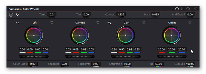
Lastly, I broke it into 4 nodes. One does the offset, one the gain (white balance), one the Gamma (which is basically the CCM) and a fourth last node for taste adjustments.

The matched color correction was saved as a memory in Resolve.

Switching between scans entailed applying the memory to the new material, then adjust first the offset and gain, leaving the gamma node untouched. That brought colors visually similar to the source, but since the source is presently faded Ektachrome, the fourth node was used to compensate for the fading and getting good colors/skin-tones.

Will retest after I get some Kodachrome scanned, but it was an interesting test, and a process to begin the taste-adjustment of the linear file starting with a known color setup.

For the above test:

  • Color Science: DaVinci YRGB Color Manager.
  • Color Processing Mode: SDR Rec.709
  • Output Color Space: Rec.709 Gamma 2.4
  • For TIFF Clip: Input Color Space: Linear

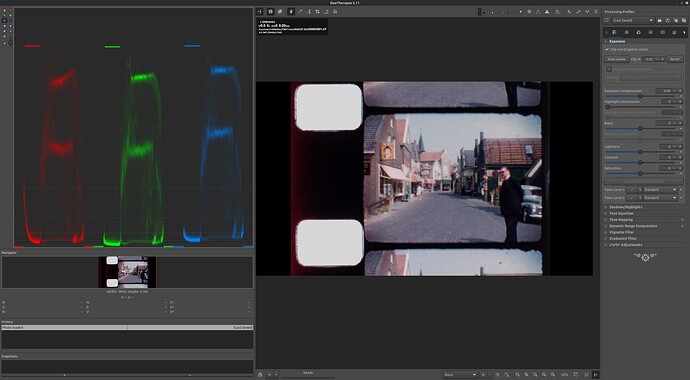
For posting, Davinci Resolve Delivered 16bit TIFF, screenshots on Rawtherapee.
DNG


Linear TIFF

2 Likes

@PM490 - quite impressive results.

But I think

is at least mathematically not correct. A ccm is a linear matrix-transformation, described by at least six different numbers, the Gamma a non-linear function, described at most with three values (for each color channel a different one).

You might try to experiment a litttle with setting the input raw node of Davinci to “Linear” (instead of “Rec.709” - in this way the gains of your second node (used as whitebalancing node) would work as indented. Of course, you would need to add a color space transformation after this, going from “Linear” to “Rec.709” for your further pipeline.

1 Like

@npiegdon: Extending a little bit my journey with raw files and Davinci:

Here’s my current result, first as vectorplot (note: no clipping):


and here as image

(That should be viewed on an sRGB-display)

This was achieved by this timeline color setting:


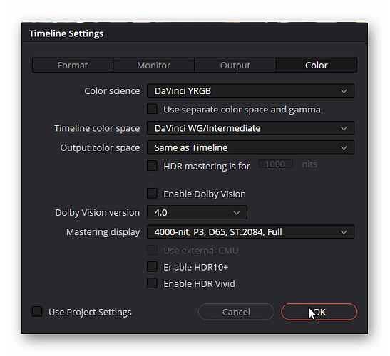
I am using DaVinci YRGB as basic “Color science”, “Timeline color space” is set to DaVinci WG/Intermediate and “Output color space” is Same as Timeline.

Now the important settings. The largest color space the raw converter of DaVinci can output with a known gamma-function is P3 D60 - and that’s what I am using as setting of the raw converter:

Important: the “Gamma” setting is selected as Linear. We will soon add appropriate processing nodes on the Color page.

The only adjustment I am doing at the raw tab is the “Exposure” value. With my raws, I usually have to dim down the exposure.

Now to the clip node tree. I use here two nodes so I easily can switch on or off the relevant things.


The first one is the important one - a “Color Space Transform” node. The input setting mimics the settings used in the raw converter. Be sure to switch off “Tone Mapping” and “Gamut Mapping” in the CST.

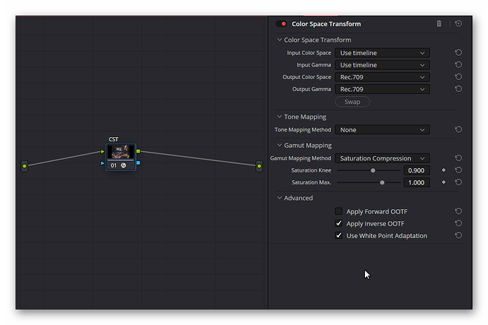
Before we go to the second node, we need to switch to the Timeline processing tree (the bullets/dropdown menues at the top of the node graph window). Here, select the following settings:


This is were our final output space gets defined. Note that I selected here “Gamut Mapping Method” as Saturation Compensation - this is my favorite, as it dims too saturated colors into the available gamut. Most of the time, the difference to selecting None or Clip is hard to spot. Only very saturated colors are modified by this setting.
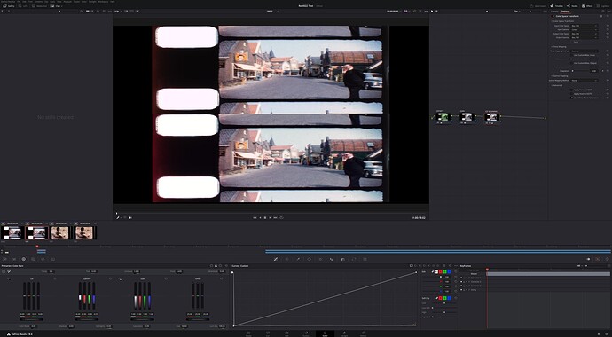
Going back to the clip node tree. The second node of that tree is used for basic color adjustments. In this case, I arrived at the following settings:


Basically some gain adjustments to get the grey patches into my taste of grey, following by some iterative adjustments of the overall gamma and contrast values.

All of that gives me the image (+ vectorscope display) posted above. I have tried this technique with scanned Kodachrome and Agfa Moviechrome footage, and it seems to work for these two types of film stock - sort of. In fact, still experimenting… :innocent:

2 Likes

@cpixip great results, and thank you for sharing the step by step.

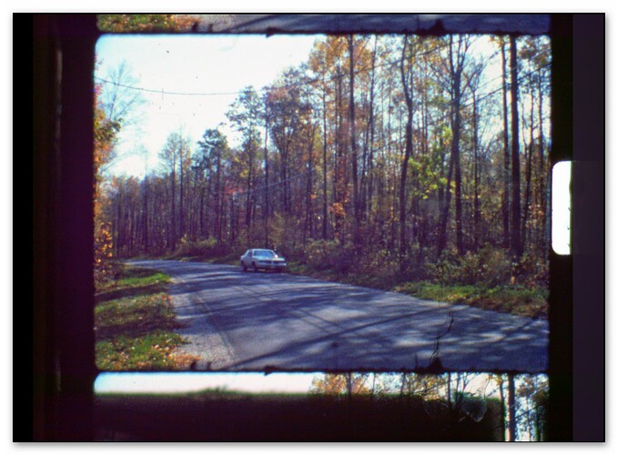
After replicating the timeline and color settings, there is an offset on the DNG. I am using an older version of resolve (18.6 running on linux), but I wonder if there is a difference in the DNG developer, or if it is something on the RPi4 DNG

Maybe I am missing something on the settings, but I was unable to replicate good results (I was testing with the same street file as above).

I agree.

However, color channel controls in Resolve are interdependent, particularly between green and red. To do the matching one needs to iterate between these two, since any slight adjustment in gamma/gain on one will change the other (parade waveform). For blue that is not the case, and it behaves somewhat what I would expect from the camera adjustment days.

The setup descrived is only for the TIFF. The second node (gain) is working as white balancing, so not sure what you meant.

I did some experimenting inserting the Color Space Transform node.


(top picture TIFF with CST, bottom DNG)

There is some difference in some color tones, with very dark greens a bit less saturated than previous setup without the CST (see building dark green wall)… still experimenting.

1 Like

If you can share your “street file” as .dng, I could have a go on this.

Yep - somewhat confusing when you come from the old analog video cameras (I do :wink: ).