New Raspi HQCam - a question of (white) balance

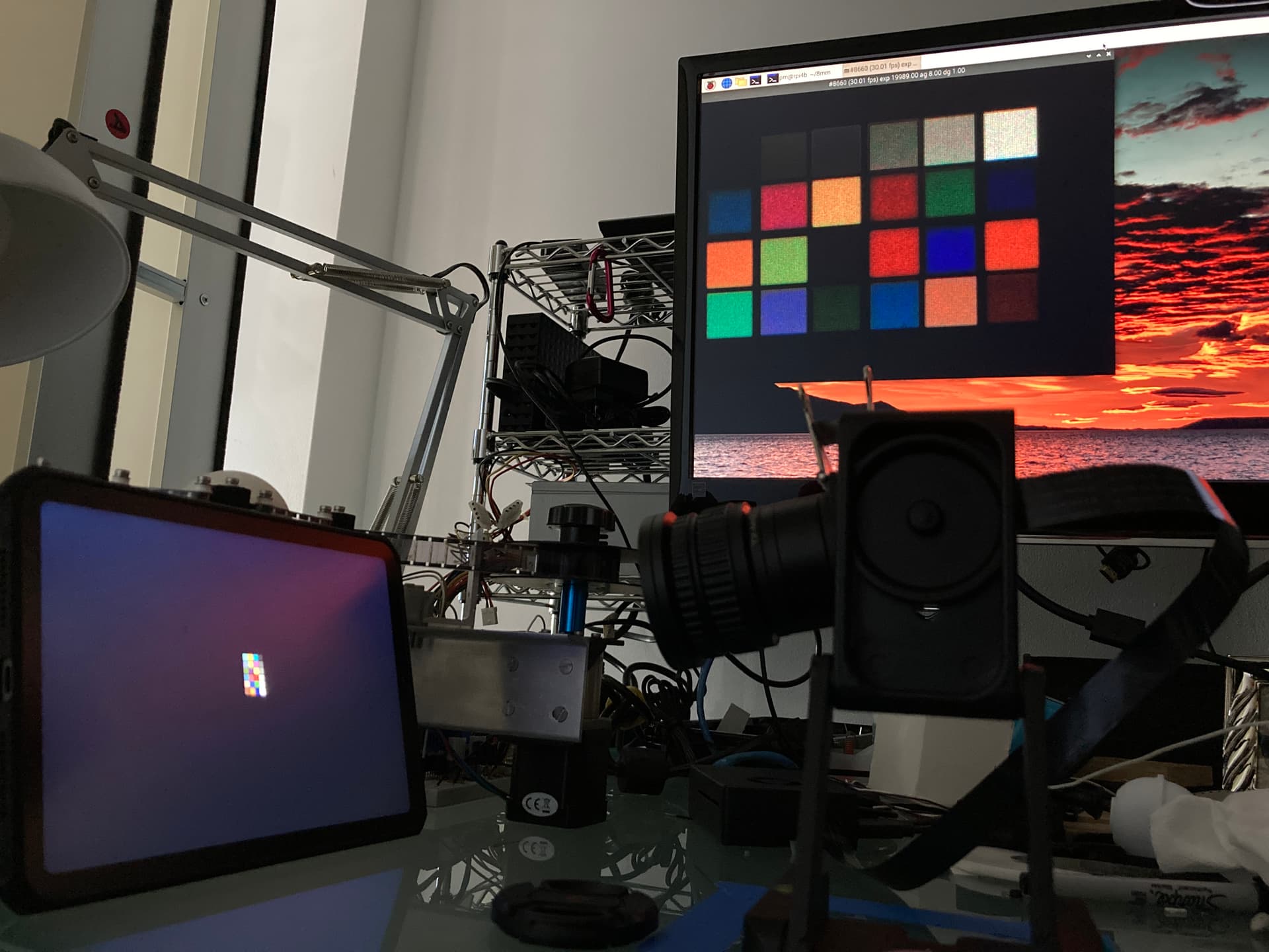
While testing the new Raspberry Pi HQCam, I stumbled about some odd behaviour. Imaging with HQCam + 16 mm standard optics an average scene with a lot of gray clouds, the auto whitebalance algorithm usually settles for red gain values of 3.3 and blue gain values of 1.5.

While the difference in value of the two gains are striking, I did a few film scans with that “normal” setting, obtaining quite satisfactory results (some examples can be seen in the New HQ Raspberry Pi Camera with C/CS-Mount thread).

For doing these scans, my LED-lightsource is routinely calibrated before the actual scan in such a way that the empty sprocket area where the light source shines through is imaged by the camera as pure white.

Now, continueing the test scans, I stumbled over a scene where the colors started to look odd. Here’s a cutout of a single frame showing this:

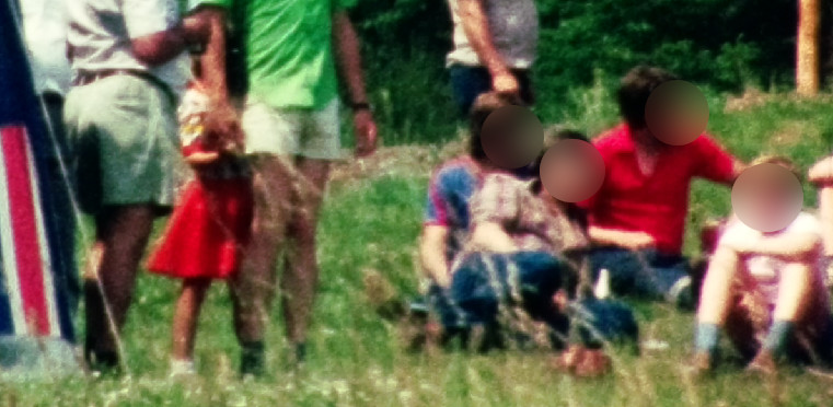
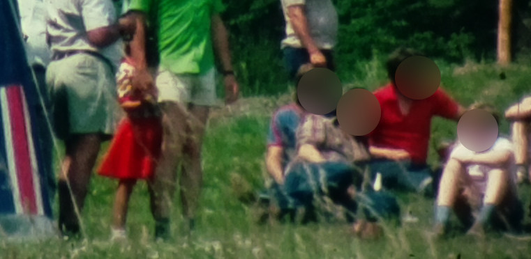
Notice specifically the red color tones, from the reddish strip of the tent (left image border) to the red skirt of the girl and the red shirt of one guy sitting to the right. These colors look weird, and if we compare them to some older scans (with the same technique: setting the whitebalance of the camera to “normal daylight gains” and adjusting the LED-source so that white is white), one can clearly see a difference. Here’s the scan with a Raspberry Pi V1-camera:

and this is the result of from a see3Cam_CU135:

Now, for the last experiment, I have set the red as well as the blue gain of the Raspi HQCam to one and adjusted the ligth source again to render as pure white in the camera output. This resulted in the LED source shining in a dramatically red light, with little green and blue. Anyway, the scan

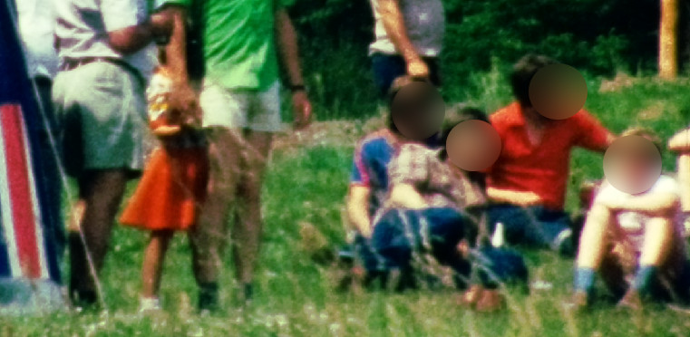
turned out to be better, colorwise, in my opinion.

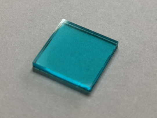
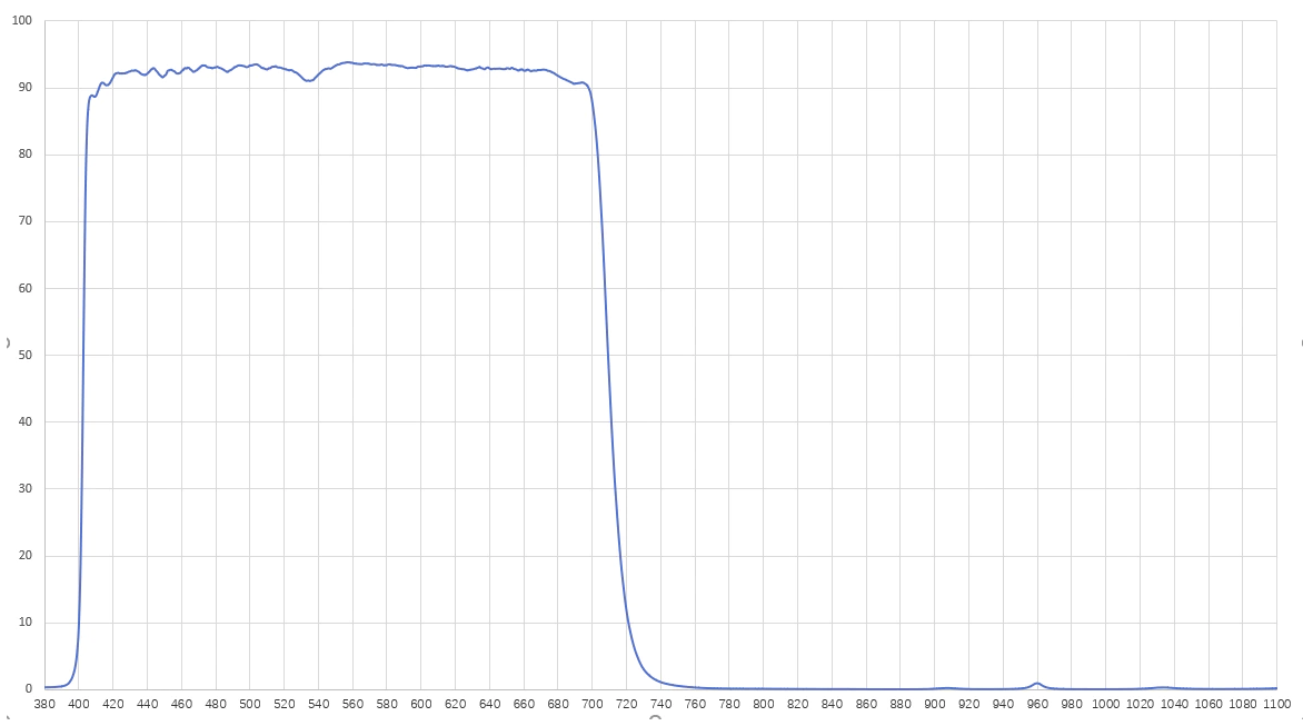
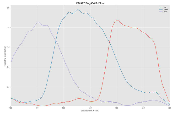
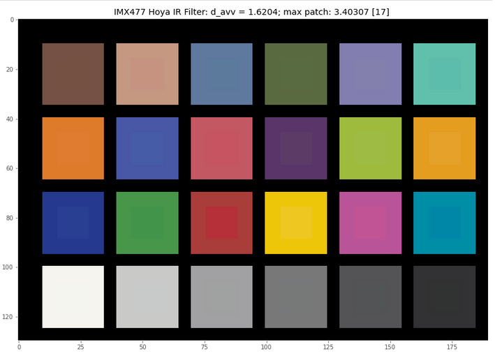
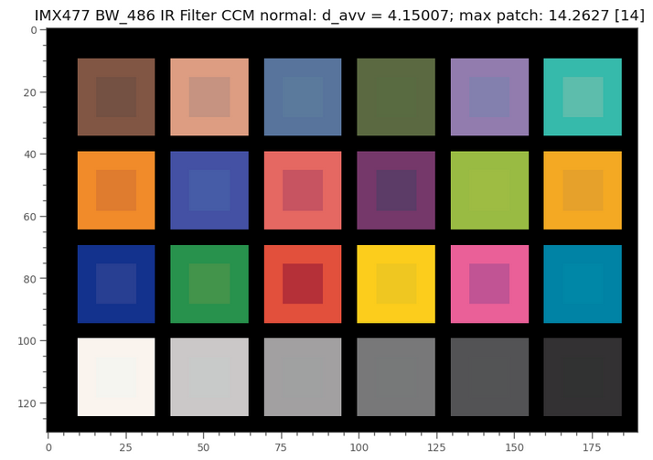
Now looking at the IR-filter of the new Raspberry Pi HQCam, one discovers that it has a quite bluish appearance. If this filter would be a good IR-cutoff filter, it would actually not appear to have any color tint.

So that might be the reason for the odd relationship between the standard red and blue gain values: the Raspberry HQCam is usually operating with a not so perfect IR-cutoff filter, which is filtering already out part of the visible red color tones. This is then compensated by software, leading to the red gain on the HQCam being usually about two times higher than the blue gain.

Normally, this seems to work fine, but in extrem settings (like lots of slightly different, intense red colors) the processing pipeline creating the JPEG-image is driven into saturation, yielding unreal red color tones.

I would be happy for any comments about this and possibly ideas on how to solve this.

I wonder, if this is a result of the LED flicker? Do you know if your LED has any flicker associated with it from the power supply? I had noticed this in some of my footage work (i’m am a hack and therefore am using an LED driven from an AC source…)

Jim

well Jim, thanks for the comment. Your point is certainly a good thing to consider.

I checked the performance of the light source throughly when I constructed that light source.

Some background information: I realize different exposures of a single frame by rapidly changing the illumination levels of my light source while keeping the camera at a fixed exposure. Later, I combine these different exposures into a single frame.

So the precision of the light source is essential to my film scanner.

The LED light source I am using is made out of three LEDs, one red, one green and one blue, which are each driven by a programmable current source. Each LED has a 12bit digital-to-analog converter, which drives the LED with the current requested by the software.

Here’s a piece of an older version of the circuit I am using (still with 10bit digital-analog-converters MCP4812 in the picture):

Not perfect, but it works. The software writes the requested current to the DAC-IC (now a MCP4822 with 12bit resolution) which drives a simple current source made out of an OpAmp (1/4 of a LM324) and a IRF101 FET (I had these parts in my part bin when I constructed this). “J1 Out” is where the LED is connected.

This current source drives the LEDs quite fast and precise. In addition, I typically wait about 5 frames after switching to a different illumination level before I capture a frame, mainly because the camera I am using is a rolling shutter camera and the imaging pipeline has a certain delay.

The above examples are direct MJPEG-captures (well, in reality: cut-outs) as they were streamed from the different cameras used.

Well, it was interesting for me to compare the scans of three different camera models (Raspberry Pi V1-camera, see3Cam_CU135 and finally the new Raspberry Pi HQCam). Franky, I did not expect such a difference in the appearance. And I actually did expect that the HQCam would perform better than it did on this particular frame. I am not sure whether this can be attributed to the camera, or whether the camera, the film and the lightsource interact in a funny way.

For normal applications, the HQCam does quite a descent job, and color test charts are rendered ok. But in the film scanner application, it seems that the HQCam performs somewhat better if I set both red and blue gains to 1.0 and set the white balance not with the camera, but with the light source.

I am thinking of exchanging the blueish stock IR-filter of the Raspi HQCam with a proper one, having a flat filter response in the visible light region (I have one in my part bin - it looks like clear glas in the visible light range and is pitch black in the infrared). If my suspicion is correct, the red gain required for a whitebalanced image would become similar to the blue gain, leading to a scan result similar to the last image in my post above. I am still a little bit hesitant, as the removal of the blueish stock IR-filter from the HQCam is an irreversible action…

Well, I finally did rip off the stock IR-cutoff filter of the HQCam. As can be seen

IR filter HQCam

this filter attenuates not only IR, but also the red parts of the visible spectrum - that’s why it looks cyan. A high quality IR-cutoff filter has a flat band in the visible spectrum and looks colorless just like optical glass.

Well, I attached instead of the stock IR-filter a B+W F-Pro 486 UV/IR-Sperrfilter MRC to my Schneider-Componon. That filter costs about as much as the HQCam and looks rather innocent, like colorless optical glass…

Normally, you would need to do a new camera calibration, and with the upcoming libcamera stack, that would actually be an option. However, the libcamera software bundle is still in it’s rough state and I won’t put any effort into this until the software is more mature and somewhat settled.

So I took the following scan still with the standard Broadcom stack, only adjusting the red and blue gains of the whitebalance algorithm to get close to a neutral gray for my light source. Well, as expected, the gain required for the red channel dropped down to 2.0. Obviously, more photons are now coming through the red channel, which improves at least the noise statistics. The blue channel gain is still at 1.5.

Here’s the scan result:

and indeed, the red on the tent, the orange-red of the child’s skirt and the red of the shirt of the guy sitting near the right border now are all distinguishable, with the light source supplying standard daylight color temperature. This was not achievable with the stock IR-filter of the HQCam, which has obviously a filter effect on the red color tones.

So, for me this challenge is solved - if you have challenging image situations, the stock IR-cutoff fillter of the HQCam might not be the optimal choice. Note however that under normal imaging conditions, the HQCam performs quite well. The issue which was discussed in this thread will only be noticable in extrem circumstances.

7 Likes

One additional piece of information: when taking raw images with raspistill, you will get information about the color matrix (ccm) applied to the raw image data to create the jpg the camera normally outputs.

I was curious how this matrix would change when different manual color gains would be set.

It turned out that the Broadcom stack (that is the standard way on the Raspberry Pi to grab images) uses just a fixed ccm with various manual red and blue gain settings.

From what the “strolls with my dog” blog

estimates, this ccm maps the raw image channels under the assumption of a color temperature of 5800K to sRGB.

I did not yet manage to run the new alternative, the libcamera stack, on my machine. But I had a look at the source code instead. With the libcamera stack again, if manual whitebalancing is used, a fixed ccm is chosen which corresponds to a color temperature of about 4500K.

Interestingly, at the moment, there is no ccm with that color temperature in the calibration data for the IMX477 (which is the sensor of the HQ cam), so the algorithm will use an interpolation. It is unknown at the moment how the Broadcom stack arrives at the fixed matrix it uses; my values are close, but not identical to “strolls with my dog”.

That a fixed ccm is used with manual whitebalancing is actually a good thing for film scanning applications. And this point was not immediately clear, at least not to me. However, it seems that taking images with red and blue gains fixed gives you in the case of Raspberry Pi cameras a constant color definition, irrespective of the actual (in a film usually quite varying) content of the scan. As it seems, no unwanted adaption, for example color temperature-wise is performed by the processing pipelines.

2 Likes

Off topic, I received my HQ camera and 16mm yesterday but only have a 20mm tube (for super 8). What extension are you using and distance to flim plane ?

@patcooper: have a look here to see my own setup, using a Schneider Componon-S 50mm lens.

Basically, as the size of the HQ cam sensor is nearly identical to the size of a slightly over-scanned Super-8 frame, you want to realize a 1:1 optical setup. Now, this is a very well-known thing. If you have a lens with focal length f, you place the object of desire (the Super-8 frame) at a distance d = 2 x f. Similar, in order to get a sharp picture, your camera sensor will need be placed the same distance d away from the lens. That’s all. So adding everything together, you end up with the distance between Super-8 frame and camera sensor being 4 x f and the lens placed midway between Super-8 frame and camera sensor.

Strictly speaking, the above is only valid for thin lenses - real lenses have different front and back focal distances which would need to be taken into account.

You can realize the appropriate distances with extension tubes, have a look at @jankaiser’s post for an example, or you can use 3D-printed extension tubes as well (my own approach, see here - stl-file at the bottom of this post).

For your 16mm lens, things might become a little bit crowded, as the approximate distance between lens and Super-8 frame would be of the order of 3 cm or so. Here, the exact locations of the front and back focal distances would be good to know because the difference between them will be of the order of these 3 cm - however, I do not have this information available for the 16 mm lens.

Besides, note that using a lens designed for imaging objects from about 1m to infinity is not the best choice for using it in a 1:1 macro imaging situation. That is why reverse mounting of a standard photographic lens is often used for macro work. The 1:1 imaging situation is however even more challenging - reverse mounting a lens would not improve the design mismatch between the operating distances the lens is calculated for vs the distances the lens is actually operated.

Many thanks, I am tight on space so 3cm lens to film would be good. Other tubes arriving soon and also the hq camera microscope lens - just for fun…

For reasons that I do not understand the filter developed some spots, so I removed it and use an external filter.

Virtually the same observed with new library, with AWB to daylight, and awbgains 1.5,2.0

Maybe that is similar to the issue described here and elsewhere?

One caveat on replacing the IR-Filter - I now know that the color characteristics will be negatively affected if one replaces the standard IR-blockfilter with another filter. The quality of the reproduced colors will be slightly less. At least this was what came out of my simulations. The slight drop in color-reproduction quality of a standard color-checker is probably not really an issue, as most of us will do a color-grading of the scanned material anyway. And usually you have to do this, as the original Super-8 film did only work either in Tungsten 3400 K or “Daylight” - both of these color temperatures were basically never realized in any filming situation.

In fact, newer HQ cameras do (or: will) feature a slightly different IR-blockfilter than the older ones; there was recently an update on the standard imx477.json tuning file because of this:

ipa: raspberrypi: imx477: Update tuning file for the latest camera modules

The latest camera modules have a very slightly different IR filter, so
the tuning file is slightly revised to give best results with both old
and new camera modules.

The original tuning file is retained as imx477_v1.json in case anyone
should wish to continue using it.

1 Like

Exactly… looks like I am following your steps, a couple of years behind.

I read your comments regarding your experience. I have not done extensive testing, but as you indicate, color correction is a necessary evil for our application.

I switch the light to the reference LED I have been using, and the gain values for red and blue are fairly close now obviously due to the color temperature of the LED, which is the one you may recall had a flatter response.

libcamera-still --awb=daylight --awbgains 1.72,1.74 --tuning-file='imx477_scientific.json' --encoding=png  --immediate=1 --shutter=9000 -o 16mmtest.png

The frame was intentionally chosen, other film parts are better exposed.

Ok, let’s dive for fun into the wonderful world of color science. This here

is the spectral characteristic of the normal HQ camera. This camera uses (or now rather: did use) a Hoya IR block filter. I did replace this IR filter in an attempt to improve color reproduction with a much more expensive BW_486 filter, which has a similar filter curve as the one you posted above. Of course, that did not work…

The spectral sensitivity functions of the camera are noticeably changed with the more expensive block filter:

Note especially the difference in the red channel.

Now, if I take a (virtual) color checker board and have the normal HQ camera with a Hoya-filter looking at this, the best I can obtain is the following image:

In the center region of every color patch the corresponding reference color is drawn. If you look closely and your monitor is not too bad, you will notice color differences between the central reference patch and surrounding area which shows what the camera would record in this situation. The patch with the largest color difference is in this case patch 17, the cyan patch. Overall, the average deviation from “being perfect” is calculated to be 1.6, which is quite a good value.

If we’re doing the same simulation with the HQ camera equipped with the BW_486, we get the following image:

The overall results is slightly worse (d_avv = 2.6 instead of 1.6) and the most offending patch is patch 12 (blue).

These results are obtained under the assumption that we use the optimized color transformation matrix for each camera. For me, it was a slightly unexpected result - the much more expensive BW_486 performed less well than the original Hoya.

It even can get worse. If we do not use in the BW_486 simulation the optimal color matrix, but the one which the normal HQ camera would use (this matrix would be taken from the tuning file), we obtain the following display:

The color deviations are now quite noticeable. Most offending is patch 14 (red) - that is, just the colors I wanted to “improve” with my surgery. However, at the time I started this thread, it somehow did improve the reds. That might be because the light source I used at this time were three narrow-band LEDs for red, green and blue. Since then, I have switched my illumination setup back to white-light LEDs. The simulations above have also been done with daylight illumination (D65).

Thank you for sharing detail analysis, colors are endless source for good stuff.

In a long past life, I used to repair professional video cameras (tube and early ccd). It was said, videotape machines are repaired by those with knowledge, cameras by those with patience.

I don’t have the depth of knowledge on color spaces to make mathematical sense of the unexpected results.

What I am seeing as most significantly (with my old camera repair guy eye) is the Y matrix looks off. It was set for a lower energy red (above).
Having more Y, and then normalizing Y for the chart, would bring the higher colors down. With the better filter, one expects “more red”, but the test with charts (normalizing for Y) fools the perception into thinking the result is the opposite: that the better filter is producing less red.

Using the better filters, is letting more red go through, also less deep-blue. In old analog cameras, the Y matrix was 0.59 G + 0.3 R + 0.11 B. A bit more or less B would be less noticeable in Y. Additional R would.

With the new filter:

  • Less Deep Blues component (Blue Circle).
  • More Red component (Red Circle).
  • Some Red light is captured as also more Green component (Yellow Circle) pushing Reds to Yellows.

When normalizing for Y the opposite is captured:

  • Patches with Deep Blue component are exaggerated.
  • Patches with Red component are dimmed.
  • Patches combining Red/Green (Yellows) are slightly shifted to Red.

PS. I think that the raw capture would allow for color correction to match the chart, yet color correction would be required.

Thoughts?

@PM490 : well, these are results of a complete matrix applied to the raw color channels. With normal cameras, the green channel is never touched (always the norm for the other channels). A first step is to apply multipliers to the red and green channels to estimate a color temperature and map the initial raw values in such a way that neutral patches are indeed neutral (i.e., have the same amplitude in RGB). In a second step a color matrix is applied to these white-balanced values. This color matrix maps from RGB to YXZ-space and there is a wild mixing of all color channels happening here. Finally, the XYZ-values are transfered back (by a fixed matrix) to final linear RGB-values.

Anyway - let me check again the calculations presented above. I am sure about the two different filter curves I presented, and the color checker images should be ok as well. But not 100% sure, as these were generated by a new script I quickly hacked together to illustrate my point. I will check this as time permits.

Thanks @cpixip. I am a bit lost in color translation.

Just to confirm my understanding, the above is a simulation of the HQ with own filter best case scenario.

I setup a quick and dirty experiment to have a qualitative idea of the color quality of the HQ with the factory IR removed, and using the UV/IR filter above.

The @cpixip above simulation was taken and center spots were removed, and tested with Resolve 17 color match, to have the percentage readings for each spot.

A TIFF was created with the ideal colors. For reference also presented below to confirm 0% in all targets.

This TIFF file was used as a source, and presented with an iPadmini (6th Generation). First using most of the screen, and a iPhoneSE (2021) camera was used to capture the target as comparison point.

Lastly, the same iPadmini (6th Gen) screen was used, with a reduced presentation of the same TIFF source color target, under similar lens conditions used for capturing the 16mm test above (Nikkor EL 50mm 2.8 @ f5.6).

The capture above was made in raw (DNG) with the following command, then color matched with resolve 17.

$ libcamera-still --awb=daylight --awbgains 1.72,1.74 --tuning-file='imx477_scientific.json' --encoding=png  --immediate=1 --shutter=20000 -o colortarget.png -r

All presentations above used 2x vectorscope in Resolve.

I haven’t had the time to digest the above, but since you are looking at the particulars of the simulation thought it would be good to share.

My first impression is that for the scanning application, the color -after color correction, and considering the small portion of the ipad screen- is not bad at all.

Below a picture of the setup for illustration.

@PM490 - unfortunately, an Ipad (or any other computer display, for that matter) does not work as a test target for testing color reproduction. The thing is: camera calibration is based on the spectra of the different color patches, working together with the illumination spectra and the filter response curves of the camera to yield three amplitudes per pixel. Technically, a continuous function is condensed into just three numbers (the three amplitudes recorded in the raw image). The same happens in your very own eye, just with different filter responses. Ideally, your camera sees the world like you - but as we all know, this can technically only be realized as an approximation.

So, while an IPad or any other display will show you (as a human being) something close to the colors the patch should have (it is designed to do this), the emission spectrum of the Ipad will be only three rather narrow-banded spikes - totally different of the spectrum of a real color target under, say daylight or tungsten illumination. So it is not a good idea to test a camera with an Ipad. An Ipad display is not designed as a camera target.

Here’s another thought experiment: Imagine imaging a flower and displaying this image on a monitor. Now hold the same flower in front of your monitor. If all of your equipment is properly color calibrated, you should not notice any difference in color. But the spectrum the real flower is emitting is totally different from the spectrum the image of the flower on your monitor is emitting. While the flower spectrum will be rather broad, maybe with a peak in the yellow-orange region of the spectrum (if it’s a sun flower), the image of the flower on your display will be mostly a sharp peak in the green, plus a peak of similar height in the red.

On the other side of the whole color thing, one can ask oneself whether those tiny variations really do matter. Super-8 film was designed with a tungsten illumination and was modified for “daylight” with an in-camera filter. Basically never did the actual color temperature of the scene match any of these two possibilities. So Super-8 shows color deviations just by design. I have a film which was shot under fluorescent light, showing therefore a nice greenish tint on surfaces with neutral colors. Of course, you can correct this in the post, but in the end, it is a matter of taste whether you do this or keep the original appearance in your digital copy.

Also, old film stock shows color variations between rolls of the same film material as well as different development labs and times - so there is a lot of color deviations backed in the whole process. Not to speak about film stock which has faded away over time. So in the end, the tiny deviations we are discussing here might not be that important… :innocent:

Thanks for providing, as usual, a sound physical perspective of light.

Agree. As said at the onset the purpose of the experiment was to have a qualitative idea of the HQ with the factory filter removed and a different filter. My concern was if the red channel was degraded. Perhaps qualitative was not the appropriate term, basically it was a comparison of the HQ with IR/UV vs iPhone camera. If the iPhone can capture the reds, it would be a point of reference to see what the HQ would be missing.

Actually, these reasons you elaborate with the targets, are somewhat analogous to the use the white LED as illuminant vs the narrow RGB LEDs.

Agree. This setup (ipad screen) can show the level variation of the primary colors only (from camera to camera), which was useful for me for comparison.

The ability of the scanning processing chain to capture the film variations, I think is important (white LED discussion). But as you said, matching colors and capturing color variations are different goals.

The concern with the IR filter was sparked by your simulation results. While as you indicate, the removal of the factory blueish IR would affect the color rendition, I have not yet seen issues with Red as depicted in the simulation.

Thanks again.